EP0038769A2 - Verfahren und Anlagen, um ein Wärmetauschfluidum in einem mit einer Wärmequelle und einer Kältequelle versehenen geschlossenen Kreislauf umlaufen zu lassen - Google Patents
Verfahren und Anlagen, um ein Wärmetauschfluidum in einem mit einer Wärmequelle und einer Kältequelle versehenen geschlossenen Kreislauf umlaufen zu lassen Download PDFInfo
- Publication number
- EP0038769A2 EP0038769A2 EP81430008A EP81430008A EP0038769A2 EP 0038769 A2 EP0038769 A2 EP 0038769A2 EP 81430008 A EP81430008 A EP 81430008A EP 81430008 A EP81430008 A EP 81430008A EP 0038769 A2 EP0038769 A2 EP 0038769A2
- Authority
- EP
- European Patent Office
- Prior art keywords
- tank
- valve
- source
- liquid
- circuit
- Prior art date
- Legal status (The legal status is an assumption and is not a legal conclusion. Google has not performed a legal analysis and makes no representation as to the accuracy of the status listed.)
- Granted
Links
Images

Classifications
-
- F—MECHANICAL ENGINEERING; LIGHTING; HEATING; WEAPONS; BLASTING
- F28—HEAT EXCHANGE IN GENERAL
- F28D—HEAT-EXCHANGE APPARATUS, NOT PROVIDED FOR IN ANOTHER SUBCLASS, IN WHICH THE HEAT-EXCHANGE MEDIA DO NOT COME INTO DIRECT CONTACT
- F28D15/00—Heat-exchange apparatus with the intermediate heat-transfer medium in closed tubes passing into or through the conduit walls ; Heat-exchange apparatus employing intermediate heat-transfer medium or bodies
- F28D15/02—Heat-exchange apparatus with the intermediate heat-transfer medium in closed tubes passing into or through the conduit walls ; Heat-exchange apparatus employing intermediate heat-transfer medium or bodies in which the medium condenses and evaporates, e.g. heat pipes
- F28D15/0266—Heat-exchange apparatus with the intermediate heat-transfer medium in closed tubes passing into or through the conduit walls ; Heat-exchange apparatus employing intermediate heat-transfer medium or bodies in which the medium condenses and evaporates, e.g. heat pipes with separate evaporating and condensing chambers connected by at least one conduit; Loop-type heat pipes; with multiple or common evaporating or condensing chambers
-
- F—MECHANICAL ENGINEERING; LIGHTING; HEATING; WEAPONS; BLASTING
- F24—HEATING; RANGES; VENTILATING
- F24S—SOLAR HEAT COLLECTORS; SOLAR HEAT SYSTEMS
- F24S50/00—Arrangements for controlling solar heat collectors
-
- F—MECHANICAL ENGINEERING; LIGHTING; HEATING; WEAPONS; BLASTING
- F25—REFRIGERATION OR COOLING; COMBINED HEATING AND REFRIGERATION SYSTEMS; HEAT PUMP SYSTEMS; MANUFACTURE OR STORAGE OF ICE; LIQUEFACTION SOLIDIFICATION OF GASES
- F25B—REFRIGERATION MACHINES, PLANTS OR SYSTEMS; COMBINED HEATING AND REFRIGERATION SYSTEMS; HEAT PUMP SYSTEMS
- F25B27/00—Machines, plants or systems, using particular sources of energy
-
- Y—GENERAL TAGGING OF NEW TECHNOLOGICAL DEVELOPMENTS; GENERAL TAGGING OF CROSS-SECTIONAL TECHNOLOGIES SPANNING OVER SEVERAL SECTIONS OF THE IPC; TECHNICAL SUBJECTS COVERED BY FORMER USPC CROSS-REFERENCE ART COLLECTIONS [XRACs] AND DIGESTS
- Y02—TECHNOLOGIES OR APPLICATIONS FOR MITIGATION OR ADAPTATION AGAINST CLIMATE CHANGE
- Y02E—REDUCTION OF GREENHOUSE GAS [GHG] EMISSIONS, RELATED TO ENERGY GENERATION, TRANSMISSION OR DISTRIBUTION
- Y02E10/00—Energy generation through renewable energy sources
- Y02E10/40—Solar thermal energy, e.g. solar towers
Definitions
- the subject of the present invention is a method and devices of the heat pump type for circulating a heat transfer fluid between a hot source and a cold source, distant and connected by a closed circuit at constant volume, in order to ensure a heat exchange between the hot spring and cold source.
- a heat pump according to the invention provides no work to the outside environment and therefore has zero efficiency. Therefore, in application of the CARNOT principle, a heat pump according to the invention can circulate a heat transfer fluid between a hot source and a cold source whose temperature difference is small.
- Heat pumps or thermocompressors are known, for example those which are described in the following patents, FR 1464982 (Conduction Corporation), US - A 4,036,019, 4,135,366, 4,180,982 and FR 75 13,297 (I. Siégel), US 3 407 626 (R. Turnblade), US 3 648 458 (R. Mc Alister), US 3 053 198 (H. Staehle), US 2 688 923 (F. Bonaventura), DE - A 2 617 025 (Dornier).
- the liquid phase of the heat transfer fluid having passed through the hot source is circulated in order to transport the maximum number of calories from the hot source to the cold source and to reduce the temperature difference between these two. sources.
- a maximum heat exchange between the two sources is obtained for a reduced flow of heat-transfer liquid.
- An objective of the present invention is to circulate a heat transfer fluid in a closed circuit between a hot source and a cold source in order to exchange calories between the two sources, using autonomous means, independent of any other energy source. than that which is due to the temperature difference between the two sources, even if the temperature difference between the two sources is relatively small, and if the two sources are distant from each other.
- the invention results in new autonomous thermal pumps making it possible to circulate a heat transfer fluid in a closed circuit at constant volume, therefore without providing any work outside.
- a pump according to the invention makes it possible to exchange calories between a hot source and a cold source using only the energy due to the temperature differences of the two sources.
- the heat transfer liquid circulates from a first reservoir connected to the hot source to a second reservoir connected to the cold source under the effect of the pressure difference between the two sources and it accumulates l mechanical, potential or kinetic energy.
- the liquid returns from the second tank to the first under the effect of the mechanical energy accumulated during the first phase.
- the devices according to the invention being autonomous can operate in isolated sites, without any contribution of mechanical or electrical energy.
- the heat pumps according to the invention are especially suitable as circulation pumps for equipping water heating installations with solar collectors.
- the circulation pumps according to the invention are self-regulating because the flow of heat transfer fluid varies in the same direction as the temperature difference between the solar collector and the hot water storage tank.
- the solar energy collection installations comprising a circulator according to the invention are very simple and very robust, the other fact that they have no moving parts / only valves and a valve which can be a float valve, very simple.
- the circulation pumps according to the invention are easy to maintain by unskilled personnel and they can operate for a very long time without supervision and without maintenance.
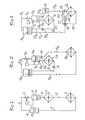
- the heat pump represented by FIG. 1 comprises a hot source 1 and a cold source 2. It also comprises a first chamber or closed tank 3, located above and near the hot source, and a second chamber or closed tank 4 which is located at an altitude greater than or equal to that of the reservoir 3. These two chambers 3 and 4 contain a liquid in phase equilibrium with the vapor.
- a circuit consisting of portions 9, .10 and 11 connects the lower parts of the two chambers 3 and 4 to each other, passing through the hot source 1 and through the cold source 2.
- the tanks 3 and 4, connected together by the pipes 6 , 9, 10, 11 form a closed circuit with constant volume which contains a constant quantity of fluid which is in the liquid and gaseous state.
- the vapor pressure in chamber 4 is lower than in chamber 3, and as the liquid in chamber 3 heats up, the level drops in the chamber 3 and rises in chamber 4, hence a circulation of the liquid through the hot and cold sources under the effect of the pressure difference.
- the heat supplied by the hot source is partially transferred to the cold source and partly transformed into kinetic and potential energy of the liquid which is discharged to a higher level.
- a liquid level sensor located in one or the other of the two tanks controls the opening of the valve 5 , which puts in direct communication the upper parts of the two tanks through the pipe 6.
- These two tanks then form two communicating vessels and the liquid contained in the tank 4 flows, by gravity to the tank 3 through the pipe 11, 10, 9, until the level of the liquid-vapor interface reaches a lower threshold in the reservoir 4 or an upper threshold in the reservoir 3 which is detected by the level sensor which controls the closing of the valve 5, and a new cycle begins again.
- the cold source can be at a level lower than that of the hot source, which is a characteristic difference compared to the circuits in which a liquid circulates by thermosyphon where the hot liquid rises from the hot spring to cold sources. Another difference is the fact that the speed of movement of fluids is relatively high compared to thermosyphon systems.
- the liquid contained in the tank 4 heats up at the opening of the valve 6 by bringing it into contact with the steam coming from the tank 3, it is therefore a heated liquid which returns to the cold source by the pipeline 11.
- the distance between the sources is nevertheless limited because the volume of each of the lines 10 and 11 must be less than the volume of liquid displaced so that liquid is exchanged between the sources.
- FIG. 2 represents another embodiment of a heat pump according to the invention which differs from the previous one in that the flow of liquid between the hot source and the cold source is unidirectional and the hot source is constantly traversed by bottom up.
- the distance between the hot and cold sources is not limited if the insulation of the pipes is satisfactory.
- the parts homologous to those of FIG. 1 are represented by the same reference mark followed by the index a.
- the reservoir 4a is located at a level higher than that of the reservoir 3a.
- the difference in altitude between the levels of the liquids in the two tanks is sufficient for the corresponding static pressure to allow the liquid to overcome the resistance of the non-return valve 13, placed on the conduit 12 connecting the bottom of the upper tank to the source. hot.
- the direction of the valve 13 is such that the liquid from the upper reservoir can flow only in the direction of the hot source and the lower reservoir through the pipes 12 and 9a.
- the conduit 10a connects the bottom of the lower reservoir to the cold source by means of the valve 14 which allows the flow of the liquid only in the direction of the reservoir 3a towards the cold source 2a.
- the conduit 11a connects the lower part of the cold source to the upper part of the reservoir 4a.
- One of the reservoirs preferably the reservoir 3a, has two level sensors 7a and 8a, the second reservoir 4a has a volume greater than the first so as to be able to absorb the additional volume due to the expansion of the liquid with the temperature without the operation of the installation is disturbed.
- This liquid after having been cooled by passing through the cold source, progresses through the conduit 11a and opens into the upper part of the reservoir 4a where it condenses the vapor.
- This condensation of vapor creates a suction effect which is favorable for the flow of the liquid.
- the valve 5a opens automatically when the level of the liquid-vapor interface has reached the threshold corresponding to the low level sensor 8a.
- the equalization of the vapor pressures in the two tanks following the opening of the valve 5a, causes the liquid to flow from the upper tank to the hot source and the lower tank through the conduit 12 and the non-return valve. 13; when the liquid-vapor interface in the reservoir 3a reaches the level of the sensor 7a a new cycle begins.
- the liquid circulates alternately from the reservoir 3 to the reservoir 4 and vice versa, it always circulates in the same direction from the hot source to the cold source and it therefore makes it possible to transport calories from the hot source to the cold source.
- the volume of the tanks 3 and 4 can be much less than that of the pipes and that of the hot and cold sources by the fact that the circulation is unidirectional and by the fact that the liquid flows through the hot source from bottom to top, the liquid expelled through the valve 14 is thus at high temperature.
- the distance between the two hot and cold sources can be relatively large because the pressure difference in the tanks 3 and 4 is sufficient to ensure the circulation of the liquid in a long circuit, the only static resistances to overcome being those of the valves and the difference in altitude between the two high and low tanks.
- the flow in the duct 10a connecting the hot source to the cold source is variable, it depends on the pressure drop in the ducts and on the difference between the pressures in the high and low tanks, and therefore this flow is linked to the 'temperature difference between the sources and the nature of the fluid.
- the fluid contained in the installation is chosen according to the temperatures of the two sources in order to have a pressure difference sufficient to ensure the circulation of the fluids.
- Water can be used for hot spring temperatures above 80 ° C.
- a more volatile fluid such as alcohol can be mixed with water.
- the mixture has a lower freezing point than pure water, on the other hand safety is ensured in the event of a leak in the primary circuit and mixing with domestic hot water, the mixture of water and alcohol very diluted not generally considered toxic.
- the range of chlorofluorinated carbon compounds covers the area of medium and low temperatures.
- trichlorotrifluoroethane with the formula CFCl 2 -CF 2 Cl, pure or diluted in white spirit, can be used.
- FIG. 3 schematically represents a heat exchange system between two sources comprising two improvements with respect to that of FIG. 2: the flow of the liquid is uninterrupted in the conduits of the cold source as long as the latter is at a temperature lower than the hot spring temperature.
- the cold source is isolated when the hot source cools and becomes colder than the cold source.
- the advantage of continuous flow is to allow better heat exchange at the level of the cold source.
- This FIG. 3 comprises a third closed tank 15, located below the tank 3b.
- a conduit carrying the valve 14b connects the upper part of the reservoir 15 to the bottom of the reservoir 3b.
- the bottom of the reservoir 15 is connected to the upper part of the cold source by the conduit 10b through the non-return valve 16.
- a conduit 17 communicates with the conduit 10b and with one channel of a three-way valve 18 of which the other two channels are connected one to the conduit 11b, the other to the conduit 19, coming from the lower part of the cold source.
- This valve 18 has two stable states; it connects the conduit 17 to the conduit llb or else the conduit 19 to the conduit 11b.
- the change of state of the three-way valve is controlled by the difference between the temperature of the cold source and the temperature of the liquid in the conduit 10b.
- the valve 20 connects the conduit Ilb to the lower part of the hot spring.
- the lower tank 3b comprises the two level sensors 7b and 8b, the upper tank 4b has a larger volume than the tanks 3b and 15 combined. It also makes it possible to contain the excess liquid due to the expansion of the liquid.
- the device allowing a continuous flow is constituted by the elements 15 and 20.
- the device allowing a regulation of the thermal contributions to the cold source is constituted by the elements 16, 17 and 18. These two devices play independent roles.
- the device allowing the regulation of the thermal contributions to the cold source works in the following way: two temperature probes 45,46 compare the temperature of the liquid coming from the hot source by the conduit 10b with the temperature of the cold source. If the temperature of the cold source is the lower of the two, the three-way valve 18 connects the conduits 19 and 11b and the liquid. Flows through the valve 16 through the cold source. If the temperature of the cold source is higher than that of the liquid contained in the conduit 10b, the three-way valve connects the conduit 17 with the conduit Ilb The liquid thus flows directly from the conduit 10b to the conduit 11b avoiding the source cold.
- the lower part of the cold source is isolated by the three-way valve 18, the upper part of the cold source is insulated by the valve 16, so that the cold source is completely isolated from the rest of the circuit and therefore cannot yield heat to the rest of the installation.
- valve 18 and the valve 16 do not substantially modify the circuit of the liquid in the cold source, this circuit becomes comparable to that of FIG. 2.
- the reservoir 3b is filled with liquid up to the level of the high level sensor 7b, the valve 5b is closed, the rise in temperature, due to the heat coming from the hot source, causes an increase in pressure.
- the valve 14b opens and the reservoir 15 fills with liquid which then flows through the conduit 10b and the cold source to rise in the upper tank through the conduit llb.
- the level in the tank 3b reaches the lower threshold corresponding to the level sensor 8b, the automatic valve 5b opens and the pressure in the tank 3b drops, which causes the non-return valve 14b to close. The pressure in the tank 15 is then the highest in the installation.
- the liquid contained in the conduits 10b, 19, 11b has acquired kinetic energy at the time of the opening of the valve 5b, it continues its movement which is facilitated by the internal overpressure in the accumulator tank 15.
- the valve 5b When the valve 5b is open, the pressure is the same on both sides of the valve 20, and the liquid can flow directly from the conduit llb to the hot source by passing through the non-return valve 20.
- the liquid can thus quickly fill the reservoir 3b from the conduit 12b and conduit 11b.
- the valve 5b closes.
- the increase in pressure due to the rise in temperature is initially reinforced by the pressure due to the kinetic energy of the liquid arriving through the valve 20.
- the valve 14b opens, including faster than during the first cycle. If the pressure in the hot source and in the tank 3b is sufficient to keep the valves 13 and 20 closed, the liquid can continue to flow thanks to its kinetic energy in the tank 4b until the valve 5b s' open.
- the flow of the liquid through the cold source is therefore variable but always in the same direction.
- the role of the reservoir 15b can be accomplished by the part of the pipe located at the outlet of the valve 14b, if this pipe has a sufficient volume near the tank 3b.
- the flow in the hot source is pulsed but the heat exchange between the hot source and the tank 3b is permanent.
- the hot source yields heat by vaporization of the liquid which rises in the conduit 9b to heat the contents of the tank 3b, which causes a very high heat exchange effective although the liquid is generally immobile in the hot source.
- FIG. 4 schematically represents an installation comprising two different hot sources operating in parallel with a single cold source and a common pipe, with two conduits, connecting the hot sources to the cold source.
- Hot springs have the ability to supply calories at different times and at different times. different rhythms.
- These sources can be, for example, two groups of insolators of different surfaces or orientations.
- the lower part of FIG. 4 represents a simplified device making it possible to avoid heat losses from the cold source ⁇ when the hot source is no longer at a sufficient temperature. This device operates independently and can therefore find its place in the installations described in the previous figures. It may not be taken into account when interpreting the operation of the devices in the upper part of FIG. 4.
- the homologous elements associated with each of the two hot sources are represented by the same reference mark followed by the index d or g respectively depending on whether it is the first or the second hot source.
- the common elements are represented by a reference followed by the letter c, when they have already been presented in the previous figures.
- Each of the hot springs 1g or ld is associated with a lower tank 3g or 3d comprising an automatic valve 5g or 5d, controlled by the level of the liquid in each lower tank.
- Each of the reservoirs is connected by a valve 14g or 14d to the accumulator reservoir 15c.
- Each reservoir 3g or 3d is placed in communication with the accumulator reservoir 15c only when its pressure becomes greater than that of said accumulator reservoir.
- the liquid from this reservoir passes through the hot source and reaches the upper part of the upper reservoir 4c via the conduit llc where it condenses the vapor.
- the valves 13d, 20d or 13g, 20g allow the liquid to enter the hot source corresponding to the valve which is open.
- a calibrated valve 22 then allows the liquid from the accumulator tank to reach via the conduits 17c and llc the upper tank. This circulation allows the liquid in the pipes to rise in temperature at the start of operation of the installation.
- the valve 22 is calibrated so that it does not allow the liquid to pass when the valves 23 and 21 are open.
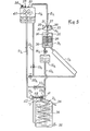
- FIG. 5 schematically represents an application of a heat pump according to the invention.
- heat transfer is ensured between a solar collector Ih, acting as a hot source, and a heat exchanger tube 2h acting as a cold source, said heat exchanger tube being embedded in the water contained in a tank 24 which is for example a domestic hot water preparation tank.
- a heat transfer fluid in equilibrium with its vapor fills the primary circuit of the installation.
- the tank 24 has a cold water inlet 25 at the base and a heated water outlet 26 at the top.
- This valve comprises a valve 27, articulated around an axis of rotation 28, a spring 29 is fixed to the valve and to an anchoring point 30 so that this spring is slightly compressed.
- the positions of the spring anchoring points are such that the valve has two stable states in its rotation about the axis 28. In one of these states, the valve closes the seat 31 located at the top; in the Another stable state, the valve is open.
- the valve 27 is linked to a rod 32 by a hinge pin 33, parallel to the axis 28, so that the upward and downward movements of the rod respectively cause the valve to open and close.
- the rod 32 carries two stops 35 and 36.
- the reservoir 3h contains an annular float 34 which can slide freely around the rod 43 between the two stops 35 and 36.
- the level of the liquid in the 3h tank gradually decreases as the liquid is transferred to the 4h tank through the 15h accumulation tank and the 2h coil.
- the float. 34 reaches the stop 36, it rests on the latter and as the liquid continues to descend, the apparent pea of the float 34 increases and it ends up driving down the rod 32 and the valve 27.
- the vapor pressures in the two tanks 3h and 4h equalize and :: the liquid of the tank 4h flows by gravity towards the tank 3h through the valve 13h, the liquid coming from the accumulator tank 15h and from the source cold enters the hot spring via the 20h valve; these flows continue until the valve 27 closes.
- Closing the valve 20h again forces the liquid from the foam source to rise in the upper part of the tank 4h.
- a spraying device 40 constituted by a perforated conduit, allows this liquid to quickly condense the vapor thus causing a suction effect and the new cycle continues.
- the spring 29 allows the valve to have two stable states, in particular during opening, the valve is not closed by the sudden passage of steam from the tank 3h to the tank 4h.
- the tank 4h carries a manual drainer 37, a safety valve 38 and a filling plug 39.
- the source loss protection device consists of two valves 23h and 21h which are joined together in their translation movements by a rod 43 sliding in a tube of narrow section comprising seals 44.
- the seat 41 of the valve 23h has a larger section than the seat 42 of the valve 21h, so that the assembly of the two valves is kept closed when the fluid contained in the coil 2h has a pressure higher than the fluid of the rest of the installation.
- the valve 41 has a spring which tends to close it in the absence of stress from the fluids.
- the calibrated valve 22h allows a diversion to the liquid when the assembly constituted by the valves 23h and 21h is closed.
- the installation may include one or more circulation lights constituted for example by propellers driven by the movement of the liquid (elements not shown in the figure).
- An interesting application of heat pumps according to the invention relates to absorption refrigeration machines.
- Such machines include a primary refrigerant circuit in connection with a boiler, a condenser and an evaporator, all three consisting of heat exchangers comprising independent secondary circuits.
- a primary refrigerant circuit in connection with a boiler, a condenser and an evaporator, all three consisting of heat exchangers comprising independent secondary circuits.
- One or more of these secondary circuits can be fitted with heat pumps according to the invention.
- the hot source is a solar collector
- the heat can be transferred to the boiler by a circuit conforming to that of FIG. 2, the hot source being constituted by a solar collector, preferably of the concentration type) and the source cold by the secondary circuit of the boiler of the absorption machine.
- the two circulation pumps operating at different temperatures, it is interesting to fill their circuits with different liquids, for example a mixture of water and alcohol for the circuit pump comprising the boiler and the solar collector and a chlorofluoride carbide for the circuit in relation to the condenser.
- a mixture of water and alcohol for the circuit pump comprising the boiler and the solar collector and a chlorofluoride carbide for the circuit in relation to the condenser.
Landscapes
- Engineering & Computer Science (AREA)
- Physics & Mathematics (AREA)
- Mechanical Engineering (AREA)
- Thermal Sciences (AREA)
- General Engineering & Computer Science (AREA)
- Sustainable Development (AREA)
- Life Sciences & Earth Sciences (AREA)
- Sustainable Energy (AREA)
- Chemical & Material Sciences (AREA)
- Combustion & Propulsion (AREA)
- Filling Or Discharging Of Gas Storage Vessels (AREA)
- Heat-Pump Type And Storage Water Heaters (AREA)
- Engine Equipment That Uses Special Cycles (AREA)
Applications Claiming Priority (2)
| Application Number | Priority Date | Filing Date | Title |
|---|---|---|---|
| FR8008847 | 1980-04-18 | ||
| FR8008847A FR2480864A1 (fr) | 1980-04-18 | 1980-04-18 | Chauffe-eau solaire et pompes fluidiques polythermes a volume total constant |
Publications (3)
| Publication Number | Publication Date |
|---|---|
| EP0038769A2 true EP0038769A2 (de) | 1981-10-28 |
| EP0038769A3 EP0038769A3 (en) | 1982-10-20 |
| EP0038769B1 EP0038769B1 (de) | 1985-07-24 |
Family
ID=9241128
Family Applications (1)
| Application Number | Title | Priority Date | Filing Date |
|---|---|---|---|
| EP81430008A Expired EP0038769B1 (de) | 1980-04-18 | 1981-04-15 | Verfahren und Anlagen, um ein Wärmetauschfluidum in einem mit einer Wärmequelle und einer Kältequelle versehenen geschlossenen Kreislauf umlaufen zu lassen |
Country Status (6)
| Country | Link |
|---|---|
| US (1) | US4366853A (de) |
| EP (1) | EP0038769B1 (de) |
| JP (1) | JPS5723795A (de) |
| DE (1) | DE3171464D1 (de) |
| FR (1) | FR2480864A1 (de) |
| MA (1) | MA19123A1 (de) |
Cited By (1)
| Publication number | Priority date | Publication date | Assignee | Title |
|---|---|---|---|---|
| FR2568674A1 (fr) * | 1984-08-03 | 1986-02-07 | Baudino Etienne | Dispositif generateur d'energie par l'exploitation simultanee de deux sources de temperatures differentes agissant sur une capacite etanche et motrice de condensation. |
Families Citing this family (18)
| Publication number | Priority date | Publication date | Assignee | Title |
|---|---|---|---|---|
| DE3219680A1 (de) * | 1982-05-21 | 1983-11-24 | Siemens AG, 1000 Berlin und 8000 München | Waermepumpenanlage |
| JPS5932870U (ja) * | 1982-08-25 | 1984-02-29 | 三菱電機株式会社 | 熱伝達装置 |
| JPS60290A (ja) * | 1983-06-15 | 1985-01-05 | Matsushita Electric Ind Co Ltd | 熱搬送装置 |
| JPS6044767A (ja) * | 1983-08-19 | 1985-03-09 | Sanyo Electric Co Ltd | 錠環集熱システム |
| JPS6062556A (ja) * | 1983-09-14 | 1985-04-10 | Mitsubishi Electric Corp | 太陽熱コレクタ |
| CA1215582A (en) * | 1983-12-02 | 1986-12-23 | Benoit Jean | Vapor pressure pump |
| US4649900A (en) * | 1984-02-08 | 1987-03-17 | Trihey John M | Solar tracking system |
| US4686831A (en) * | 1984-12-18 | 1987-08-18 | Silva Robert E | System and method of delivering low/pressure/low temperature fluids into high pressure/high temperature heat exchangers by means of alternate pressure equalization |
| LU86434A1 (fr) * | 1986-05-22 | 1987-06-26 | Euratom | Dispositif pour le transfert passif de chaleur |
| US6042342A (en) * | 1996-10-02 | 2000-03-28 | T.D.I. --Thermo Dynamics Israel Ltd. | Fluid displacement system |
| ES2347752B1 (es) * | 2009-04-06 | 2011-09-22 | Abengoa Solar New Technologies, S.A | Receptor solar con circulacion natural para generacion de vapor saturado. |
| DE102010011084A1 (de) * | 2010-03-12 | 2011-09-15 | Converteam Gmbh | Kühlvorrichtung und Verfahren zum Kühlen eines Betriebsmittels |
| PL217073B1 (pl) * | 2010-07-26 | 2014-06-30 | Univ Warmińsko Mazurski W Olsztynie | Sposób samoczynnego przekazywania ciepła w kierunku odwrotnym do konwekcji naturalnej i urządzenie do samoczynnego przekazywania ciepła w kierunku odwrotnym do konwekcji naturalnej |
| US20120103280A1 (en) * | 2010-10-08 | 2012-05-03 | Dan Russell Wells | Variable flow heating system with heating accessories placed in series |
| JP6584416B2 (ja) | 2014-01-24 | 2019-10-02 | ビーエーエスエフ ソシエタス・ヨーロピアBasf Se | 太陽熱発電所のための配管系 |
| US11530529B2 (en) * | 2019-01-29 | 2022-12-20 | John Saavedra | Heat transfer system utilizing dynamic fluid leveling |
| FR3141236A1 (fr) * | 2022-10-19 | 2024-04-26 | Pierre Bignon | Machine thermique |
| FR3141218B1 (fr) * | 2022-10-19 | 2024-10-18 | Pierre Bignon | Compresseur thermique |
Family Cites Families (32)
| Publication number | Priority date | Publication date | Assignee | Title |
|---|---|---|---|---|
| US209742A (en) * | 1878-11-05 | Improvement in hot-water heating apparatus | ||
| US1148857A (en) * | 1915-01-29 | 1915-08-03 | Anders Borch Reck | Hot-water heating apparatus. |
| US1658412A (en) * | 1922-01-06 | 1928-02-07 | Parker Philip | Heating system |
| US1886243A (en) * | 1927-10-22 | 1932-11-01 | David L Gordon | Absorption refrigeration apparatus |
| US2068549A (en) * | 1933-05-23 | 1937-01-19 | Servel Inc | Heat transfer system |
| US2230917A (en) * | 1938-05-25 | 1941-02-04 | Triana Pedro Grau | Lifting of liquids by solar heat |
| US2210607A (en) * | 1938-10-19 | 1940-08-06 | Servel Inc | Refrigeration |
| US2210511A (en) * | 1938-10-19 | 1940-08-06 | Servel Inc | Refrigeration |
| US2195293A (en) * | 1938-10-19 | 1940-03-26 | Servel Inc | Refrigeration |
| US2226797A (en) * | 1938-12-29 | 1940-12-31 | Servel Inc | Refrigeration |
| US2366955A (en) * | 1941-09-20 | 1945-01-09 | Servel Inc | Refrigeration |
| FR1001963A (fr) * | 1946-07-08 | 1952-02-29 | Dispositif automatique pour le transvasement de liquides | |
| US2688923A (en) * | 1951-11-05 | 1954-09-14 | Filiberto A Bonaventura | Solar energy pump |
| FR1169114A (fr) * | 1957-02-28 | 1958-12-23 | Centrale thermo-solaire | |
| US3053198A (en) * | 1958-02-21 | 1962-09-11 | Midland Ross Corp | Thermopump system |
| GB995128A (en) * | 1960-10-12 | 1965-06-16 | English Electric Co Ltd | Improvements in or relating to fluid-circulating apparatus |
| US3407626A (en) * | 1965-02-24 | 1968-10-29 | Conductron Corp | Thermal refrigeration apparatus |
| US3285001A (en) * | 1965-03-04 | 1966-11-15 | Conductron Corp | Thermal fluid moving apparatus |
| GB1213327A (en) * | 1968-05-09 | 1970-11-25 | Hawker Siddeley Dynamics Ltd | Improved apparatus for transferring fluid coolant from a fluid reservoir to a vessel of use |
| US3648458A (en) * | 1970-07-28 | 1972-03-14 | Roy E Mcalister | Vapor pressurized hydrostatic drive |
| US3846984A (en) * | 1974-04-29 | 1974-11-12 | I Siegel | Temperature differential fluid motor |
| AR219049A1 (es) * | 1975-07-24 | 1980-07-31 | Tacchi V | Combinacion de un captador de energia solar y disposicion orientadora para el mismo |
| US4036019A (en) * | 1975-11-10 | 1977-07-19 | Israel Siegel | Solar differential temperature motor |
| US4061131A (en) * | 1975-11-24 | 1977-12-06 | Acme Engineering And Manufacturing Corporation | Heat transfer system particularly applicable to solar heating installations |
| DE2617025C2 (de) * | 1976-04-17 | 1983-03-31 | Dornier System Gmbh, 7990 Friedrichshafen | Arbeitsmaschine zur Nutzung der Exergie eines Dampfes |
| US4135366A (en) * | 1976-08-02 | 1979-01-23 | Israel Siegel | Valveless differential temperature engine |
| FR2380448A1 (fr) * | 1977-02-11 | 1978-09-08 | Commissariat Energie Atomique | Procede de mise en circulation ou de controle de la circulation d'un liquide dans un circuit |
| US4180982A (en) * | 1977-03-21 | 1980-01-01 | Israel Siegel | Instant return-stroke differential temperature engine |
| MX147216A (es) * | 1977-08-23 | 1982-10-25 | Victorio Tacchi | Mejoras en sistema para transferir fluido calentado por energia solar desde un nivel superior a uno inferior |
| EP0001382A3 (en) * | 1977-10-11 | 1979-08-08 | Kurt Leczkowski | Methods and installations for producing utilisable energy and/or cold from heat |
| US4148195A (en) * | 1977-12-12 | 1979-04-10 | Joseph Gerstmann | Liquid piston heat-actuated heat pump and methods of operating same |
| DE2756585A1 (de) * | 1977-12-19 | 1979-06-21 | Roland Ing Grad Bruestle | Wasserfoerdereinrichtung mit sonnenkollektor |
-
1980
- 1980-04-18 FR FR8008847A patent/FR2480864A1/fr not_active Withdrawn
-
1981
- 1981-04-15 DE DE8181430008T patent/DE3171464D1/de not_active Expired
- 1981-04-15 MA MA19328A patent/MA19123A1/fr unknown
- 1981-04-15 EP EP81430008A patent/EP0038769B1/de not_active Expired
- 1981-04-16 US US06/254,788 patent/US4366853A/en not_active Expired - Fee Related
- 1981-04-18 JP JP5786781A patent/JPS5723795A/ja active Pending
Cited By (2)
| Publication number | Priority date | Publication date | Assignee | Title |
|---|---|---|---|---|
| FR2568674A1 (fr) * | 1984-08-03 | 1986-02-07 | Baudino Etienne | Dispositif generateur d'energie par l'exploitation simultanee de deux sources de temperatures differentes agissant sur une capacite etanche et motrice de condensation. |
| WO1986001254A1 (fr) * | 1984-08-03 | 1986-02-27 | Etienne Baudino | Dispositif generateur d'energie par l'exploitation simultanee de deux sources de temperature differentes agissant sur une capacite etanche |
Also Published As
| Publication number | Publication date |
|---|---|
| FR2480864A1 (fr) | 1981-10-23 |
| DE3171464D1 (en) | 1985-08-29 |
| JPS5723795A (en) | 1982-02-08 |
| EP0038769A3 (en) | 1982-10-20 |
| US4366853A (en) | 1983-01-04 |
| EP0038769B1 (de) | 1985-07-24 |
| MA19123A1 (fr) | 1981-12-31 |
Similar Documents
| Publication | Publication Date | Title |
|---|---|---|
| EP0038769B1 (de) | Verfahren und Anlagen, um ein Wärmetauschfluidum in einem mit einer Wärmequelle und einer Kältequelle versehenen geschlossenen Kreislauf umlaufen zu lassen | |
| FR2584228A1 (fr) | Dispositif de refroidissement de secours a surete intrinseque d'un reacteur nucleaire a eau sous pression. | |
| AU2011283286B2 (en) | A method and device for self-acting heat transfer in a direction reverse to natural convection | |
| FR2694076A1 (fr) | Système de réfrigération et son procédé de fonctionnement. | |
| FR2484088A1 (fr) | Calorimetre a flux de chaleur et son procede de fonctionnement | |
| CA2980400A1 (fr) | Dispositif solaire de production autonome de froid par sorption solide-gaz | |
| CA1244732A (fr) | Thermovanne bi-directionnelle, installation pour la production et le stockage de chaleur ou de froid comportant une telle thermovanne et utilisations diverses | |
| FR2551536A1 (de) | ||
| CA1227978A (fr) | Systeme de chauffage solaire par changement de phases | |
| FR2519384A1 (fr) | Procede et dispositifs pour faire circuler un liquide caloporteur dans un circuit ferme comportant une source chaude et une source froide | |
| FR2538088A1 (fr) | Appareil de transmission de chaleur | |
| FR2514477A1 (fr) | Chauffe-eau solaire compact | |
| EP4605693A1 (de) | Wärmekraftmaschine | |
| EP2947393B1 (de) | Schutzumlauf gegen überhitzungseffekte in einem heisswasserbereitungssystem, und entsprechendes heisswasserbereitungssystem | |
| EP4605652A1 (de) | Thermischer verdichter | |
| FR2524126A1 (fr) | Dispositif de stockage de chaleur et source froide pour pompe a chaleur comportant un tel dispositif | |
| FR2478273A1 (fr) | Installation pour chauffer un fluide caloporteur et de l'eau de consommation dans des immeubles | |
| FR2540613A1 (fr) | Dispositif de transmission de chaleur | |
| FR2926351A1 (fr) | Dispositif de chauffage de l'eau | |
| BE893310A (fr) | Dispositif d'accumulation et d'utilisation de la chaleur solaire | |
| EP3392595A2 (de) | Verteilungssystem eines wärmeübertragungsmittels für eine wärmeenergie-speichervorrichtung, die thermostatsysteme umfasst | |
| FR2588642A1 (fr) | Procede et installation de chauffage central | |
| BE406891A (de) | ||
| FR2534362A1 (fr) | Dispositif de transmission de chaleur | |
| BE478129A (de) |
Legal Events
| Date | Code | Title | Description |
|---|---|---|---|
| PUAI | Public reference made under article 153(3) epc to a published international application that has entered the european phase |
Free format text: ORIGINAL CODE: 0009012 |
|
| AK | Designated contracting states |
Designated state(s): BE CH DE FR GB IT |
|
| PUAL | Search report despatched |
Free format text: ORIGINAL CODE: 0009013 |
|
| AK | Designated contracting states |
Designated state(s): BE CH DE FR GB IT |
|
| 17P | Request for examination filed |
Effective date: 19830110 |
|
| ITF | It: translation for a ep patent filed | ||
| GRAA | (expected) grant |
Free format text: ORIGINAL CODE: 0009210 |
|
| AK | Designated contracting states |
Designated state(s): BE CH DE FR GB IT LI |
|
| REF | Corresponds to: |
Ref document number: 3171464 Country of ref document: DE Date of ref document: 19850829 |
|
| PLBE | No opposition filed within time limit |
Free format text: ORIGINAL CODE: 0009261 |
|
| STAA | Information on the status of an ep patent application or granted ep patent |
Free format text: STATUS: NO OPPOSITION FILED WITHIN TIME LIMIT |
|
| 26N | No opposition filed | ||
| PG25 | Lapsed in a contracting state [announced via postgrant information from national office to epo] |
Ref country code: LI Effective date: 19870430 Ref country code: CH Effective date: 19870430 |
|
| BERE | Be: lapsed |
Owner name: BERNIER JEAN-PAUL Effective date: 19870430 |
|
| GBPC | Gb: european patent ceased through non-payment of renewal fee | ||
| REG | Reference to a national code |
Ref country code: CH Ref legal event code: PL |
|
| PG25 | Lapsed in a contracting state [announced via postgrant information from national office to epo] |
Ref country code: DE Effective date: 19880101 |
|
| REG | Reference to a national code |
Ref country code: FR Ref legal event code: ST |
|
| REG | Reference to a national code |
Ref country code: FR Ref legal event code: AR |
|
| PG25 | Lapsed in a contracting state [announced via postgrant information from national office to epo] |
Ref country code: GB Effective date: 19881118 |
|
| PG25 | Lapsed in a contracting state [announced via postgrant information from national office to epo] |
Ref country code: BE Effective date: 19890430 |
|
| PGFP | Annual fee paid to national office [announced via postgrant information from national office to epo] |
Ref country code: FR Payment date: 19910503 Year of fee payment: 11 |
|
| PG25 | Lapsed in a contracting state [announced via postgrant information from national office to epo] |
Ref country code: FR Effective date: 19911230 |
|
| REG | Reference to a national code |
Ref country code: FR Ref legal event code: ST |