EP0038954B1 - Pompe à béton automobile - Google Patents
Pompe à béton automobile Download PDFInfo
- Publication number
- EP0038954B1 EP0038954B1 EP81102490A EP81102490A EP0038954B1 EP 0038954 B1 EP0038954 B1 EP 0038954B1 EP 81102490 A EP81102490 A EP 81102490A EP 81102490 A EP81102490 A EP 81102490A EP 0038954 B1 EP0038954 B1 EP 0038954B1
- Authority
- EP
- European Patent Office
- Prior art keywords
- trailer
- concrete pump
- tractor
- semi
- pump according
- Prior art date
- Legal status (The legal status is an assumption and is not a legal conclusion. Google has not performed a legal analysis and makes no representation as to the accuracy of the status listed.)
- Expired
Links
- 230000008878 coupling Effects 0.000 claims description 14
- 238000010168 coupling process Methods 0.000 claims description 14
- 238000005859 coupling reaction Methods 0.000 claims description 14
- 230000000087 stabilizing effect Effects 0.000 claims description 3
- 230000000903 blocking effect Effects 0.000 claims 2
- 239000000725 suspension Substances 0.000 claims 1
- 230000001960 triggered effect Effects 0.000 claims 1
- 230000007246 mechanism Effects 0.000 abstract description 12
- 230000003028 elevating effect Effects 0.000 abstract 1
- 238000010276 construction Methods 0.000 description 8
- 230000004888 barrier function Effects 0.000 description 1
- 230000005540 biological transmission Effects 0.000 description 1
- 238000011161 development Methods 0.000 description 1
- 230000018109 developmental process Effects 0.000 description 1
- 230000003203 everyday effect Effects 0.000 description 1
- 238000009415 formwork Methods 0.000 description 1
- 238000003780 insertion Methods 0.000 description 1
- 230000037431 insertion Effects 0.000 description 1
- 238000005086 pumping Methods 0.000 description 1
- 238000012353 t test Methods 0.000 description 1
Images

Classifications
-
- E—FIXED CONSTRUCTIONS
- E04—BUILDING
- E04G—SCAFFOLDING; FORMS; SHUTTERING; BUILDING IMPLEMENTS OR AIDS, OR THEIR USE; HANDLING BUILDING MATERIALS ON THE SITE; REPAIRING, BREAKING-UP OR OTHER WORK ON EXISTING BUILDINGS
- E04G21/00—Preparing, conveying, or working-up building materials or building elements in situ; Other devices or measures for constructional work
- E04G21/02—Conveying or working-up concrete or similar masses able to be heaped or cast
- E04G21/04—Devices for both conveying and distributing
- E04G21/0418—Devices for both conveying and distributing with distribution hose
- E04G21/0436—Devices for both conveying and distributing with distribution hose on a mobile support, e.g. truck
-
- Y—GENERAL TAGGING OF NEW TECHNOLOGICAL DEVELOPMENTS; GENERAL TAGGING OF CROSS-SECTIONAL TECHNOLOGIES SPANNING OVER SEVERAL SECTIONS OF THE IPC; TECHNICAL SUBJECTS COVERED BY FORMER USPC CROSS-REFERENCE ART COLLECTIONS [XRACs] AND DIGESTS
- Y10—TECHNICAL SUBJECTS COVERED BY FORMER USPC
- Y10T—TECHNICAL SUBJECTS COVERED BY FORMER US CLASSIFICATION
- Y10T137/00—Fluid handling
- Y10T137/6851—With casing, support, protector or static constructional installations
- Y10T137/6855—Vehicle
- Y10T137/6881—Automotive
-
- Y—GENERAL TAGGING OF NEW TECHNOLOGICAL DEVELOPMENTS; GENERAL TAGGING OF CROSS-SECTIONAL TECHNOLOGIES SPANNING OVER SEVERAL SECTIONS OF THE IPC; TECHNICAL SUBJECTS COVERED BY FORMER USPC CROSS-REFERENCE ART COLLECTIONS [XRACs] AND DIGESTS
- Y10—TECHNICAL SUBJECTS COVERED BY FORMER USPC
- Y10T—TECHNICAL SUBJECTS COVERED BY FORMER US CLASSIFICATION
- Y10T137/00—Fluid handling
- Y10T137/8593—Systems
- Y10T137/8807—Articulated or swinging flow conduit
Definitions
- the invention relates to a self-propelled concrete pump of the type specified in the preamble of claim 1.
- Concrete pumps of this type convey the concrete delivered by transport mixers to construction sites via a placing boom into a formwork.
- the concrete pumps are usually mounted on 2-, 3- and 4-axle truck chassis with a continuous, rigid frame.
- 2-, 3- and 4-axle truck chassis with a continuous, rigid frame.
- axle loads are necessary, as is the case with mobile cranes. They are only allowed to drive on public roads with a special permit and cannot use many lighter routes and bridges.
- the placing boom can only have a length of up to approximately 32 m.
- this heavy ballast has to be transported in a cost-increasing manner.
- the invention has for its object to improve the known self-propelled concrete pump of the type specified in the preamble of the claim that with a relatively light design of the semitrailer without sacrificing stability, a considerable increase in the range of the placing boom is achieved without a prescribed weight limit of entire tractor-trailer is exceeded.
- tractor unit with its weight of approx. 7 to 9 t can be used as ballast for stabilizing the placing boom.
- the support legs provided on the semitrailer are pivoted laterally outward into their prescribed position and supported on the ground by means of a telescopic device while lifting the semitrailer.
- the front support legs pointing forward by about 45 ° to the vehicle axle expediently extend in front of the front axle of the tractor unit. Because of the large reach of the support legs to the front, the semitrailer, which is about 0.5 to 1 m longer than a vehicle with a rigid chassis, does not suffer any loss of useful range.
- the front axle is not used as the foremost safety edge, as is the case with mobile cranes, but rather the connecting line running in front of the front axle approximately in the area of the bumper of the tractor unit between the floor support points of the front support legs.
- the same also applies to a vehicle with a fixed common frame between the concrete pump and motor drive, provided that corresponding swing-out support legs are provided.
- the semitrailer has the advantage that it is not limited to a total weight of 22 to 24 tonnes, like a fixed vehicle, in order to be able to drive on public roads without restrictions, but up to 38 tonnes total weight with a 5-axle design and up to 32 tonnes total weight with 4-axle design.
- An additional weight of 8 tonnes for the tractor unit, with a support width of 8 m, allows an increase in the load moment of the placing boom by 30 to 40 mt and thus a corresponding increase in its length.
- the use of a semitrailer with a three-axle tractor unit and a two-axle semitrailer with a total weight of 38 t enables the construction of a placing boom with a reach height of up to 44 m and a horizontal outreach of approx. 40 m with a support width of approx. 8 m.
- a 5-axle special chassis would be required, which may only drive on public roads with large travel restrictions and special permits. This restriction is particularly unsustainable for service companies that have to drive many different types of work every day because of the high investment and transport costs. It is eliminated by the construction according to the invention.
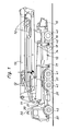
- the mobile concrete pump contains a semitrailer, on the semitrailer 10 of which a placing boom 13 is rotatable on a turret 11 about a vertical axis and can be unfolded by hydraulic means 12, the concrete line 14 of which can be loaded with the concrete to be conveyed via a charging container 15 and a pump unit 16 .
- a total of four support legs 17, 18 which can be swung out laterally and telescopically extended are provided on the semitrailer 10 (cf. FIG. 2).
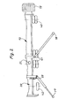
- the tractor unit 20 is detachably connected to the kingpin 19 of the semitrailer 10 via a fifth wheel coupling 21 known per se.
- the bolt 22 ensures that both vertical and horizontal power transmission via the coupling is possible and that the tractor unit can still be pivoted about the vertical axis of the kingpin 19 relative to the satellite trailer 10.
- the bolt 22 can be fixed on the fifth wheel coupling 21 by means of a suitable screw connection in such a way that it cannot be easily removed by the operating personnel.
- the pivot bearing 23 additionally provided on the fifth wheel coupling allows the tractor 20 to pitch about a horizontal transverse axis relative to the semitrailer 10.
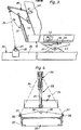
- lifting and holding means 29, which are also referred to below as the lifting mechanism, are arranged between the semitrailer and the tractor unit.
- the lifting mechanism 29 contains at least one lever 30 which is articulated on the turret 11 of the placing boom 13 or on the frame of the semitrailer 10.
- the lever 30 can be pivoted up and down with the aid of a hydraulic cylinder 31 about a horizontal axis running transverse to the direction of travel (FIG. 4).
- two hydraulic cylinders 31 can also be provided, the stroke of which can be coordinated with one another by means of a cross rod 33 (FIG. 5).
- link chains 34 are suspended, which have at their lower end an eyelet 37 which can be hung on a head bolt 36 which projects laterally beyond the chassis frame 35 of the tractor unit 20.
- the head bolts 36 are expediently arranged on a crossbar 38 fastened to the chassis frame 35, which has a further head bolt 39 in its central region located in the longitudinal center plane of the tractor unit.
- the link chains 34 serve as a pulling element, by means of which the tractor unit can be lifted off the ground when the lever 30 is pivoted up with the aid of the hydraulic cylinder 31.
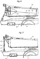
- the lifting mechanism 29 contains a hydraulic cylinder 31 ′ attached to the semitrailer 10 or to its structure, the piston rod 45 of which has an eye 47 or a hook at the free end, on which the traction element designed as a chain or rope 34 is attachable.
- the slack pulling member 34 is guided over a deflection roller 46 located on the semitrailer.
- the semitrailer 10 with its structure consisting of pump unit 16 and placing boom 13 is first raised by swiveling out and extending the support legs 17, 18, so that the rear wheels 40 are largely or completely lifted off the ground.
- the double axle 41 of the tractor unit 20 is pulled up via the closed fifth wheel 21.
- the support legs 17, 18 are approximately in the position indicated in FIG. 2.
- the lifting mechanism 29 is then actuated. Especially if the tractor unit 20 is not exactly aligned with the semitrailer 10 after arriving at the construction site, the link chains 34 are initially attached to the central headed bolts 39. When the hydraulic cylinder or cylinders 31 and 31 'are actuated, the front part of the tractor unit 20 is then raised slightly and, after the front wheels 42 has been lifted off, aligned in a position aligned with the semitrailer 10. After lowering the tractor again, the link chains 34 can then be hung on the laterally projecting head bolts 36.
- the tractor unit 20 When the hydraulic cylinder 31 or 31 'is subsequently actuated, the tractor unit 20 is lifted off the ground with its front wheels 42 and then acts as a ballast weight for stabilizing the semitrailer when the distribution boom is extended when the rear wheels 41 also come free from the ground.
- the tractor unit 20 does not execute any undesired vibrations when the heavy placing boom 13 is pivoted, it can be locked in the aligned position. This can be done with a wedge, not shown, which is known per se and which is inserted hydraulically into the insertion slot of the fifth wheel coupling 21.
- additional hydraulic cylinders not shown in the drawing, can be attached between the semitrailer 10 and the chassis 35 of the tractor unit 20.
- the raised tractor unit can be fixed relative to the semitrailer.
- a safety device that blocks the pressure oil supply to the distributor boom hydraulics when the semitrailer is unsaddled and / or when the tractor unit is not lifted off the ground.
- two switching valves 44, 45 designed as an opener are arranged on the semitrailer, which are actuated in one case by the coupling plate of the fifth wheel coupling 21 and in the other case by the lever 30 in its upwardly pivoted end position (FIG. 3).
- the security device can also be implemented in other ways, such as. B. by a responsive to the load of the raised tractor unit, connected to the hydraulic cylinder 31 pressure switch valve.
- the link chains 34 allow the tractor to be swiveled back into the original position, which has been developed relative to the semitrailer, after the work has been completed by briefly lowering the chains 34 at another point on the chassis frame 35 or the cross member 38 after a short lowering of the front part that the tractor can be swiveled towards the intended side when the trailer is raised again.
- the semitrailer can then move back in its original direction of travel and leave the construction site, especially in narrow construction sites.
- a cable winch can also be used as the lifting mechanism. If the cable winch is arranged in the rear region of the semitrailer 10 in the vicinity of the loading container 15, it can, if necessary, also be used as a towing winch for the vehicle.
Landscapes
- Engineering & Computer Science (AREA)
- Architecture (AREA)
- Mechanical Engineering (AREA)
- Civil Engineering (AREA)
- Structural Engineering (AREA)
- Vehicle Cleaning, Maintenance, Repair, Refitting, And Outriggers (AREA)
- On-Site Construction Work That Accompanies The Preparation And Application Of Concrete (AREA)
- Reciprocating Pumps (AREA)
- Structures Of Non-Positive Displacement Pumps (AREA)
- Jet Pumps And Other Pumps (AREA)
Claims (16)
Priority Applications (1)
| Application Number | Priority Date | Filing Date | Title |
|---|---|---|---|
| AT81102490T ATE5667T1 (de) | 1980-04-26 | 1981-04-02 | Selbstfahrende betonpumpe. |
Applications Claiming Priority (2)
| Application Number | Priority Date | Filing Date | Title |
|---|---|---|---|
| DE19803016232 DE3016232A1 (de) | 1980-04-26 | 1980-04-26 | Selbstfahrende betonpumpe |
| DE3016232 | 1980-04-26 |
Publications (3)
| Publication Number | Publication Date |
|---|---|
| EP0038954A2 EP0038954A2 (fr) | 1981-11-04 |
| EP0038954A3 EP0038954A3 (en) | 1981-12-23 |
| EP0038954B1 true EP0038954B1 (fr) | 1983-12-21 |
Family
ID=6101090
Family Applications (1)
| Application Number | Title | Priority Date | Filing Date |
|---|---|---|---|
| EP81102490A Expired EP0038954B1 (fr) | 1980-04-26 | 1981-04-02 | Pompe à béton automobile |
Country Status (5)
| Country | Link |
|---|---|
| US (1) | US4418713A (fr) |
| EP (1) | EP0038954B1 (fr) |
| AT (1) | ATE5667T1 (fr) |
| BR (1) | BR8102515A (fr) |
| DE (2) | DE3016232A1 (fr) |
Cited By (5)
| Publication number | Priority date | Publication date | Assignee | Title |
|---|---|---|---|---|
| WO2004113646A1 (fr) | 2003-06-25 | 2004-12-29 | Putzmeister Aktiengesellschaft | Pompe a beton transportable a mat distributeur |
| WO2004113648A1 (fr) | 2003-06-25 | 2004-12-29 | Putzmeister Aktiengesellschaft | Pompe a beton roulante pourvue d'un mat distributeur |
| WO2009097933A1 (fr) | 2008-02-06 | 2009-08-13 | Putzmeister Concrete Pumps Gmbh | Engin de travail mobile |
| CN102287055A (zh) * | 2011-06-28 | 2011-12-21 | 三一重工股份有限公司 | 一种混凝土泵车 |
| CN102943567A (zh) * | 2012-11-30 | 2013-02-27 | 上海汽车改装厂有限公司 | 一种臂架支撑以及具有该支撑的混凝土泵车 |
Families Citing this family (16)
| Publication number | Priority date | Publication date | Assignee | Title |
|---|---|---|---|---|
| US4640533A (en) * | 1985-10-04 | 1987-02-03 | Construction Forms, Inc. | Adjustable pipe extender for high pressure lines carrying abrasive materials |
| US4848012A (en) * | 1987-07-27 | 1989-07-18 | Zimmerman Harold M | Multi-purpose earthworking machine |
| DE3830315A1 (de) * | 1988-09-07 | 1990-03-08 | Putzmeister Maschf | Fahrbare betonpumpe |
| US5029895A (en) * | 1989-07-11 | 1991-07-09 | Schwing America, Inc. | Outrigger-mounted axle assembly |
| WO1993013010A1 (fr) * | 1991-12-31 | 1993-07-08 | Loya Gilbert A | Dispositif de coulage de beton polyvalent a element d'accouplement universel destine a une grue ou a un vehicule tout terrain |
| DE10032622A1 (de) * | 2000-07-07 | 2002-01-17 | Putzmeister Ag | Stützausleger für fahrbare Arbeitsmaschinen und Autobetonpumpen mit solchen Stützauslegern |
| DE10112084A1 (de) * | 2001-03-12 | 2002-09-19 | Putzmeister Ag | Fahrbare Dickstoffpumpe mit Stützkonstruktion und luftgefederter Radachse |
| US6588448B1 (en) * | 2002-01-07 | 2003-07-08 | Glazer Enterprises, Inc. | Telescopic boom-mounted concrete pump apparatus |
| DE10328769A1 (de) | 2003-06-25 | 2005-01-20 | Putzmeister Ag | Knickmast für fahrbare Betonpumpen |
| US7398981B1 (en) | 2003-11-20 | 2008-07-15 | Schwing America, Inc. | Auxiliary axle system for concrete pump truck |
| DE102008007917A1 (de) * | 2008-02-06 | 2009-08-13 | Putzmeister Concrete Pumps Gmbh | Fahrbare Arbeitsmaschine |
| CN102364007B (zh) * | 2011-10-31 | 2014-02-19 | 中联重科股份有限公司 | 混凝土泵车和折叠臂架的臂间支撑装置 |
| ES2425434B1 (es) * | 2012-04-12 | 2014-09-16 | Gicalla, S.A. | Equipo basculante removedor-descargador rápido de hormigón |
| DE102014200396A1 (de) * | 2014-01-13 | 2015-07-30 | Putzmeister Engineering Gmbh | Autobetonpumpe und Schutzschaltung dafür |
| CN111335638A (zh) * | 2020-03-10 | 2020-06-26 | 三一汽车制造有限公司 | 臂架和作业设备 |
| CN114517578B (zh) * | 2020-11-20 | 2023-04-28 | 三一汽车制造有限公司 | 作业车辆 |
Citations (1)
| Publication number | Priority date | Publication date | Assignee | Title |
|---|---|---|---|---|
| DE2737884A1 (de) * | 1977-08-23 | 1979-03-08 | Schlecht Karl | Betonpumpverteiler auf sattelfahrzeug |
Family Cites Families (7)
| Publication number | Priority date | Publication date | Assignee | Title |
|---|---|---|---|---|
| DE7240480U (de) * | 1975-07-24 | Zimmermann W | Fahrbares Hebezeug | |
| US2883208A (en) * | 1955-04-28 | 1959-04-21 | Sentinel Shrewsbury Ltd | Tractor-trailer load distributing coupling |
| US2899004A (en) * | 1955-07-08 | 1959-08-11 | Simmons Lovel Reynolds | Weight-transferring hitch for four-wheel-drive tractors |
| GB1083794A (en) * | 1964-11-09 | 1967-09-20 | Century Fabrications 100 Ltd | Cranes and other load shifting apparatus |
| US3985036A (en) * | 1973-02-15 | 1976-10-12 | Challenge-Cook Bros., Incorporated | Outrigger and mounting means for truck with a conveyor boom |
| US4130134A (en) * | 1976-12-13 | 1978-12-19 | Morgen Manufacturing Company | Material conveying apparatus |
| DE2729750A1 (de) * | 1977-07-01 | 1979-01-18 | Scheele Maschf W | Dreiteiliger knickausleger fuer eine auf einem lkw angeordnete betonfoerderanlage |
-
1980
- 1980-04-26 DE DE19803016232 patent/DE3016232A1/de not_active Withdrawn
-
1981
- 1981-04-02 EP EP81102490A patent/EP0038954B1/fr not_active Expired
- 1981-04-02 AT AT81102490T patent/ATE5667T1/de not_active IP Right Cessation
- 1981-04-02 DE DE8181102490T patent/DE3161686D1/de not_active Expired
- 1981-04-24 BR BR8102515A patent/BR8102515A/pt unknown
- 1981-04-27 US US06/257,856 patent/US4418713A/en not_active Expired - Lifetime
Patent Citations (1)
| Publication number | Priority date | Publication date | Assignee | Title |
|---|---|---|---|---|
| DE2737884A1 (de) * | 1977-08-23 | 1979-03-08 | Schlecht Karl | Betonpumpverteiler auf sattelfahrzeug |
Cited By (6)
| Publication number | Priority date | Publication date | Assignee | Title |
|---|---|---|---|---|
| WO2004113646A1 (fr) | 2003-06-25 | 2004-12-29 | Putzmeister Aktiengesellschaft | Pompe a beton transportable a mat distributeur |
| WO2004113648A1 (fr) | 2003-06-25 | 2004-12-29 | Putzmeister Aktiengesellschaft | Pompe a beton roulante pourvue d'un mat distributeur |
| WO2009097933A1 (fr) | 2008-02-06 | 2009-08-13 | Putzmeister Concrete Pumps Gmbh | Engin de travail mobile |
| CN102287055A (zh) * | 2011-06-28 | 2011-12-21 | 三一重工股份有限公司 | 一种混凝土泵车 |
| CN102943567A (zh) * | 2012-11-30 | 2013-02-27 | 上海汽车改装厂有限公司 | 一种臂架支撑以及具有该支撑的混凝土泵车 |
| CN102943567B (zh) * | 2012-11-30 | 2016-04-06 | 上海汽车改装厂有限公司 | 一种臂架支撑以及具有该支撑的混凝土泵车 |
Also Published As
| Publication number | Publication date |
|---|---|
| DE3016232A1 (de) | 1981-11-05 |
| EP0038954A2 (fr) | 1981-11-04 |
| DE3161686D1 (en) | 1984-01-26 |
| BR8102515A (pt) | 1982-01-05 |
| US4418713A (en) | 1983-12-06 |
| ATE5667T1 (de) | 1984-01-15 |
| EP0038954A3 (en) | 1981-12-23 |
Similar Documents
| Publication | Publication Date | Title |
|---|---|---|
| EP0038954B1 (fr) | Pompe à béton automobile | |
| EP0593390B1 (fr) | Grue mobile | |
| DE1944214B2 (de) | Chienenlos verfahrbarer drehkranunterwagen | |
| DE3139596A1 (de) | Schwerlast-teleskopkran | |
| AT523097B1 (de) | Fahrzeugkran mit einem teleskopausleger und fahrzeugkransystem sowie verfahren zur montage einer abspannvorrichtung an den teleskopausleger eines fahrzeugkrans | |
| DE2015792C2 (de) | Als Ackerschlepper einzusetzendes landwirtschaftliches Fahrzeug | |
| DE2944289A1 (de) | Hebefahrzeug | |
| DE19823380A1 (de) | Vorrichtung zur Verringerung der Achslast eines mehrachsigen fahrbaren Teleskopkranes | |
| DE3911868C2 (fr) | ||
| DE102021111922B3 (de) | Abspannsystem und -verfahren für einen Mobilkran-Teleskopausleger | |
| EP1037848B1 (fr) | Chassis pour dispositif de travail permettant un dechargement en un point eloigne, en particulier pour une grue de chantier elevee | |
| EP0919508B1 (fr) | Grue avec un dispositif de retenue | |
| DE19728822B4 (de) | Anbaunachlauffahrwerk | |
| DE102020121344B4 (de) | Mobilkran mit Anhänger | |
| DE10127964A1 (de) | Flurförderfahrzeug | |
| DE3245095C2 (fr) | ||
| DE2315362C3 (de) | Fahrzeug für den Transport von Stahlbetonraumzellen, insbesondere Fertiggaragen | |
| DE4024608C2 (de) | Lastwagen mit einer hydraulischen Abstützvorrichtung | |
| DE2737884A1 (de) | Betonpumpverteiler auf sattelfahrzeug | |
| DE2848387A1 (de) | Fahrzeug zum transportieren und aufstellen von fertiggaragen | |
| DE20213045U1 (de) | Mechanische Ausrüstung zur Pannenhilfe und zur Bergung von beschädigten oder liegengebliebenen schweren Kraftfahrzeugen, beliebig entweder als Hebe- bzw. Schleppgabel als Kran | |
| AT201648B (de) | Fahrbares Mehrzweckebaugerät | |
| DE2366554C1 (de) | Transportfahrzeug fuer vorgefertigte Gebaeude,insbesondere Stahlbetonfertiggaragen | |
| DE19938545A1 (de) | Nutzfahrzeug mit einem Ladekran und einer Wechselbrücke | |
| EP4053066A2 (fr) | Dispositif et procédé de montage / démontage d'une flèche de grue mobile |
Legal Events
| Date | Code | Title | Description |
|---|---|---|---|
| PUAI | Public reference made under article 153(3) epc to a published international application that has entered the european phase |
Free format text: ORIGINAL CODE: 0009012 |
|
| PUAL | Search report despatched |
Free format text: ORIGINAL CODE: 0009013 |
|
| AK | Designated contracting states |
Designated state(s): AT DE IT NL |
|
| AK | Designated contracting states |
Designated state(s): AT DE IT NL |
|
| RBV | Designated contracting states (corrected) |
Designated state(s): AT DE IT NL |
|
| 17P | Request for examination filed |
Effective date: 19820317 |
|
| ITF | It: translation for a ep patent filed | ||
| GRAA | (expected) grant |
Free format text: ORIGINAL CODE: 0009210 |
|
| STAA | Information on the status of an ep patent application or granted ep patent |
Free format text: STATUS: THE PATENT HAS BEEN GRANTED |
|
| AK | Designated contracting states |
Designated state(s): AT DE IT NL |
|
| PG25 | Lapsed in a contracting state [announced via postgrant information from national office to epo] |
Ref country code: NL Effective date: 19831221 |
|
| REF | Corresponds to: |
Ref document number: 5667 Country of ref document: AT Date of ref document: 19840115 Kind code of ref document: T |
|
| REF | Corresponds to: |
Ref document number: 3161686 Country of ref document: DE Date of ref document: 19840126 |
|
| PG25 | Lapsed in a contracting state [announced via postgrant information from national office to epo] |
Ref country code: AT Effective date: 19840402 |
|
| NLV1 | Nl: lapsed or annulled due to failure to fulfill the requirements of art. 29p and 29m of the patents act | ||
| PLBI | Opposition filed |
Free format text: ORIGINAL CODE: 0009260 |
|
| 26 | Opposition filed |
Opponent name: FRIEDRICH WILH. SCHWING GMBH Effective date: 19840919 |
|
| PLBG | Opposition deemed not to have been filed |
Free format text: ORIGINAL CODE: 0009274 |
|
| 26D | Opposition deemed not to have been filed |
Opponent name: FRIEDRICH WILH. SCHWING GMBH Effective date: 19840922 |
|
| ITTA | It: last paid annual fee | ||
| PGFP | Annual fee paid to national office [announced via postgrant information from national office to epo] |
Ref country code: DE Payment date: 19990424 Year of fee payment: 19 |
|
| PG25 | Lapsed in a contracting state [announced via postgrant information from national office to epo] |
Ref country code: DE Free format text: LAPSE BECAUSE OF NON-PAYMENT OF DUE FEES Effective date: 20000430 |