EP0039006A1 - Dispositif d'interruption et de réglage - Google Patents
Dispositif d'interruption et de réglage Download PDFInfo
- Publication number
- EP0039006A1 EP0039006A1 EP81102919A EP81102919A EP0039006A1 EP 0039006 A1 EP0039006 A1 EP 0039006A1 EP 81102919 A EP81102919 A EP 81102919A EP 81102919 A EP81102919 A EP 81102919A EP 0039006 A1 EP0039006 A1 EP 0039006A1
- Authority
- EP
- European Patent Office
- Prior art keywords
- controller
- coupling
- clutch
- switch
- coupling part
- Prior art date
- Legal status (The legal status is an assumption and is not a legal conclusion. Google has not performed a legal analysis and makes no representation as to the accuracy of the status listed.)
- Granted
Links
- 230000008878 coupling Effects 0.000 claims abstract description 48
- 238000010168 coupling process Methods 0.000 claims abstract description 48
- 238000005859 coupling reaction Methods 0.000 claims abstract description 48
- 230000005764 inhibitory process Effects 0.000 claims description 5
- 239000002184 metal Substances 0.000 claims description 4
- 230000001105 regulatory effect Effects 0.000 claims description 2
- 230000000452 restraining effect Effects 0.000 abstract 1
- 238000004519 manufacturing process Methods 0.000 description 3
- 241000209035 Ilex Species 0.000 description 2
- 239000011810 insulating material Substances 0.000 description 2
- 230000001808 coupling effect Effects 0.000 description 1
- 230000007423 decrease Effects 0.000 description 1
- 238000010438 heat treatment Methods 0.000 description 1
Images


Classifications
-
- H—ELECTRICITY
- H01—ELECTRIC ELEMENTS
- H01H—ELECTRIC SWITCHES; RELAYS; SELECTORS; EMERGENCY PROTECTIVE DEVICES
- H01H89/00—Combinations of two or more different basic types of electric switches, relays, selectors and emergency protective devices, not covered by any single one of the other main groups of this subclass
- H01H89/04—Combination of a thermally actuated switch with a manually operated switch
-
- H—ELECTRICITY
- H01—ELECTRIC ELEMENTS
- H01H—ELECTRIC SWITCHES; RELAYS; SELECTORS; EMERGENCY PROTECTIVE DEVICES
- H01H3/00—Mechanisms for operating contacts
- H01H3/54—Mechanisms for coupling or uncoupling operating parts, driving mechanisms, or contacts
- H01H3/58—Mechanisms for coupling or uncoupling operating parts, driving mechanisms, or contacts using friction, toothed, or other mechanical clutch
Definitions
- the invention relates to a switching and control device, in particular for ovens, according to the preamble of claim 1.
- Such combinations of switches and controllers are also referred to as UOG switches because they can be used to switch on bottom heat (temperature-controlled), top heat and grill position. It is therefore necessary to be able to control further switching positions of the cam switch at the end of the control range of the controller.
- the object of the invention is therefore to provide a switching and regulating device of the type mentioned at the outset which enables simplified manufacture and assembly.
- the slip or snap-in clutch becomes effective and enables the shift drum of the switch to rotate relative to the fixed setting shaft of the controller.
- the inhibition of the controller-side coupling part prevents the controller-side coupling part from immediately starting to turn back, as a result of which the synchronization between the controller and the switch would be canceled. Since the clutch runs back more easily than the controller, it is ensured that the clutch first returns to the position at which it was disengaged, and then, for example by means of a driving stop, takes the controller again.
- the inhibition of the controller-side coupling part is preferably generated by a resilient catch, but can also be generated by friction.
- the groove can be present both directly on the controller-side connection part in the area of the switch or on the controller, the natural friction in the controller being able to help at least partially.
- a clutch which could be called an intermediate thing between the slip and snap-in clutch, and which consists of two superimposed, preferably frontal clutch surfaces, which are provided with cams or toothed in such a way that they are in the engaged state in which that is, the shafts of the controller and switch rotate together, mesh with one another, while when disengaging they can lift off from each other against the force of a spring, preferably axially compressing them, and twist against each other.
- This achieves a coupling effect in which after the coupling point has been exceeded (disengagement of the cams) the resistance to turning further becomes relatively low again.
- the clutch snaps resiliently, so that the synchronization is inevitably restored.
- a driving stop acting in the reverse direction of rotation comes into engagement between the two coupling halves, which ensures a positive coupling in this direction.
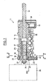
- the cam switch 11 shown in FIG. 1 has a switch housing 12 made of insulating material, in which a switch shaft 13 is mounted which drives a switching drum 14.
- the shift drum has at its remote end a deep central recess into which a sleeve-shaped coupling part 17 engages and rotates and delimits it can move axially.
- the coupling part then has, on its part guided in the recess 16, a flange 18 which covers the end surface (coupling surface 19) which is remote from the operator with the inner end surface of its flange (coupling surface 20).
- the two coupling surfaces are profiled in a manner which will be explained later.
- the flange 18 lies in a U-shaped recess 21 of the switch housing 12 and thus forms the rear bearing for the shift drum.
- the shift drum is secured in the recess 21 by a projection 22 of a rear metal plate 23 which overlaps the flange 18.
- the metal sign 23 has a multiple function.
- projections 24 for non-rotatably coupling the controller 25 and also has a leaf spring 26 in the form of a tab cut out from it, which axially on the outer end face 27 of the coupling part 17 presses and thus presses the two coupling surfaces 19 and 20 against each other.
- a recess 28 see, for example, FIG.
- the shield 23 is fastened to the housing 12 by means of spring catches 40.
- the controller 25 has an adjusting shaft 29, which is accommodated in a rotationally fixed manner in the interior of the coupling part 17.
- Figures 2 to 5 show the profile of the two coupling surfaces. It can be seen that the two profiles occupy an annular area on the end face and are mirror images of one another, so that the profiles engage in the engaged position.
- Each profiling consists of some, in the example shown 3 obliquely triangular projections and recesses (cams 30), a section 31 which springs back on the shift drum 14 and which a projecting section 32 on the coupling tion part 17 or the clutch surface 20 is opposite and a projecting on the clutch surface 19 of the shift drum section 33, which corresponds to a rear section 34 on the opposite clutch surface 20. Between the protruding and recessed sections there is a steep step 35 on both coupling surfaces 19, 20.
- FIG. 6 shows the clutch 36 engaged, in which the profiled surfaces, which correspond to one another in mirror image, rest against one another and engage in one another. This state is maintained from the switch position 0 ° (off position) to the end of the control range of the temperature controller 25.
- This control range normally ends at approximately 270 ° in the angle of rotation of the switch shaft 13 and the control shaft 29 which is synchronously coupled in this area certain desired inhibition of the switch and controller against unintentional adjustment.
- Fig. 7 shows the clutch 36 at the end of the control range (at about 270 ° setting angle). It can be seen that the clutch 36 is still engaged, i. the surfaces 19, 20 are still completely on top of each other, but the leaf spring 26 is snapped into the recess 28 so that the coupling part 17 is braked. At the same time, the range of rotation angles of the regulator shaft 29 in the temperature regulator is normally limited by a stop, so that the coupling part 17 also stops because of this.
- the switching drum 14 opens or closes 15 contacts by moving switching springs without the control shaft 29 of the temperature controller moving. 6 to 8 viewed from the right in a clockwise direction, i.e. in the direction of arrow 37, the coupling surface 19 of the shift drum 14 runs back to the coupling point (in the example at 270 °) when turning back against the direction of rotation 37. It should be noted that when disengaging after an initial resistance to the axial movement of the coupling part 17 against the force of the leaf spring 26, the adjustment of the shift drum relative to the clutch part 117 is relatively easy.
Landscapes
- Mechanical Operated Clutches (AREA)
- Air Bags (AREA)
- Selective Calling Equipment (AREA)
- Input Circuits Of Receivers And Coupling Of Receivers And Audio Equipment (AREA)
- Arrangement And Mounting Of Devices That Control Transmission Of Motive Force (AREA)
- Vehicle Body Suspensions (AREA)
- Massaging Devices (AREA)
- Oscillators With Electromechanical Resonators (AREA)
- Controls For Constant Speed Travelling (AREA)
- Electric Stoves And Ranges (AREA)
- Electric Ovens (AREA)
Priority Applications (1)
| Application Number | Priority Date | Filing Date | Title |
|---|---|---|---|
| AT81102919T ATE4355T1 (de) | 1980-04-25 | 1981-04-15 | Schalt- und regelvorrichtung. |
Applications Claiming Priority (2)
| Application Number | Priority Date | Filing Date | Title |
|---|---|---|---|
| DE3016032 | 1980-04-25 | ||
| DE19803016032 DE3016032A1 (de) | 1980-04-25 | 1980-04-25 | Schalt- und regelvorrichtung |
Publications (2)
| Publication Number | Publication Date |
|---|---|
| EP0039006A1 true EP0039006A1 (fr) | 1981-11-04 |
| EP0039006B1 EP0039006B1 (fr) | 1983-07-27 |
Family
ID=6100966
Family Applications (1)
| Application Number | Title | Priority Date | Filing Date |
|---|---|---|---|
| EP81102919A Expired EP0039006B1 (fr) | 1980-04-25 | 1981-04-15 | Dispositif d'interruption et de réglage |
Country Status (10)
| Country | Link |
|---|---|
| US (1) | US4420072A (fr) |
| EP (1) | EP0039006B1 (fr) |
| AT (1) | ATE4355T1 (fr) |
| AU (1) | AU539578B2 (fr) |
| CA (1) | CA1172675A (fr) |
| DE (2) | DE3016032A1 (fr) |
| ES (1) | ES501598A0 (fr) |
| GR (1) | GR75599B (fr) |
| YU (1) | YU41238B (fr) |
| ZA (1) | ZA812653B (fr) |
Cited By (1)
| Publication number | Priority date | Publication date | Assignee | Title |
|---|---|---|---|---|
| EP0913846A3 (fr) * | 1997-11-03 | 1999-12-22 | DREEFS GmbH Schaltgeräte und Systeme | Sélecteur avec thermostat pour four de cuisson |
Families Citing this family (9)
| Publication number | Priority date | Publication date | Assignee | Title |
|---|---|---|---|---|
| DE3431740C2 (de) * | 1984-08-29 | 1987-02-05 | Bosch-Siemens Hausgeräte GmbH, 7000 Stuttgart | Temperatursteuereinrichtung für einen Backofen |
| DE3602282A1 (de) * | 1986-01-25 | 1987-08-20 | Ringspann Maurer Kg A | Ueberlastkupplung |
| DE3717224A1 (de) * | 1987-05-22 | 1988-12-08 | Licentia Gmbh | Back- und bratofen |
| US5347119A (en) * | 1993-06-25 | 1994-09-13 | Litton Systems, Inc. | Night vision device with dual-action artificial illumination |
| US5889259A (en) * | 1997-05-22 | 1999-03-30 | Hp Intellectual Corp. | Toaster oven control assembly |
| DE10112240A1 (de) * | 2001-03-05 | 2003-01-30 | Ego Elektro Geraetebau Gmbh | Steuerwalze für ein elektromechanisches Schaltgerät |
| DE10308450A1 (de) | 2003-02-24 | 2004-09-16 | E.G.O. Elektro-Gerätebau GmbH | Drehschalter mit Schaltwelle für ein Elektrogerät |
| US20110250598A1 (en) | 2010-04-12 | 2011-10-13 | Ulrike Fischer | Detergent free polymerases |
| CN107388829B (zh) * | 2017-08-31 | 2023-03-10 | 中铁隆昌铁路器材有限公司 | T形棒料的定位加热机构及方法 |
Citations (4)
| Publication number | Priority date | Publication date | Assignee | Title |
|---|---|---|---|---|
| DE1168991B (de) * | 1957-08-22 | 1964-04-30 | Driescher Spezialfab Fritz | Antriebseinrichtung zum wahlweisen Schalten von Trennschaltern mehrerer Stromkreise |
| DE1615225A1 (de) * | 1967-02-16 | 1970-06-04 | Ego Elektro Blanc & Fischer | Schalt- und Regelvorrichtung an Backoefen von Elektroherden |
| DE2164694A1 (de) * | 1971-12-27 | 1973-07-12 | Bbc Brown Boveri & Cie | Elektrischer nockenschalter mit angekoppeltem weiteren schaltgeraet |
| DE2803768A1 (de) * | 1977-01-31 | 1978-10-26 | Ego Regeltech | Elektrischer nockenschalter mit angekuppeltem drehschalter |
Family Cites Families (19)
| Publication number | Priority date | Publication date | Assignee | Title |
|---|---|---|---|---|
| US1833774A (en) * | 1931-11-24 | Burner igniting device | ||
| US2561136A (en) * | 1945-07-04 | 1951-07-17 | Case Co J I | Overload release coupling |
| US2765375A (en) * | 1953-05-14 | 1956-10-02 | Gen Motors Corp | Domestic appliance |
| DE1717895U (de) * | 1955-12-21 | 1956-03-01 | Kueppersbusch | Schalt- und regelvorrichtung fuer elektroherde. |
| US2823638A (en) * | 1956-06-13 | 1958-02-18 | Midwest Mfg Corp | Range heat indicator |
| DE1028254B (de) * | 1956-11-23 | 1958-04-17 | Karl Fischer | Schalt- und Regeleinrichtung an Backoefen von Elektroherden |
| DE1065107B (de) * | 1958-04-29 | 1959-09-10 | Karl Fischer | Schalt- und Regeleinrichtung an Backoefen von Elektroherden |
| US2935591A (en) * | 1958-06-23 | 1960-05-03 | Westinghouse Electric Corp | Electric oven control |
| US3172998A (en) * | 1962-06-27 | 1965-03-09 | Philco Corp | Heating apparatus |
| FR1403215A (fr) * | 1964-06-26 | 1965-06-18 | Westinghouse Electric Corp | Appareil de commande de four à température réglable pour fonctionnement en four et grillade |
| DE6802794U (de) * | 1968-10-15 | 1969-06-26 | Siemens Elektrogeraete Gmbh | Gestaengeverbindung fuer schalt- oder regelorgane in elektroherden oder dgl. |
| US3577747A (en) * | 1969-06-17 | 1971-05-04 | James Murrell Brown | Torque limiting clutch |
| DE7319859U (de) * | 1973-05-25 | 1973-12-06 | Ernst Dreefs Kg | Geratedrehschalter mit anmontier tem Schaltgerat |
| DE2351240C3 (de) * | 1973-10-12 | 1981-06-19 | Robert Bosch Gmbh, 7000 Stuttgart | Überlastkupplung |
| US3971904A (en) * | 1973-10-23 | 1976-07-27 | Illinois Tool Works Inc. | Switch assembly for gas tap assembly having cam operated leaf spring contacts and split housing cam detent stop |
| US3942337A (en) * | 1974-09-16 | 1976-03-09 | Industrial Analytics Inc. | Torque limiting device |
| DE2533547C3 (de) * | 1975-07-26 | 1978-06-01 | Licentia Patent-Verwaltungs-Gmbh, 6000 Frankfurt | Herd, insbesondere Elektroherd, mit einem herausklappbaren Schalterkasten |
| US4111358A (en) * | 1977-03-23 | 1978-09-05 | Ranco Incorporated | Oven control |
| US4340806A (en) * | 1980-01-21 | 1982-07-20 | Harper-Wyman Company | Safety latch control arrangement for self-cleaning oven |
-
1980
- 1980-04-25 DE DE19803016032 patent/DE3016032A1/de not_active Withdrawn
-
1981
- 1981-04-02 CA CA000374480A patent/CA1172675A/fr not_active Expired
- 1981-04-02 GR GR64568A patent/GR75599B/el unknown
- 1981-04-07 US US06/251,937 patent/US4420072A/en not_active Expired - Fee Related
- 1981-04-08 AU AU69198/81A patent/AU539578B2/en not_active Ceased
- 1981-04-15 EP EP81102919A patent/EP0039006B1/fr not_active Expired
- 1981-04-15 AT AT81102919T patent/ATE4355T1/de not_active IP Right Cessation
- 1981-04-15 DE DE8181102919T patent/DE3160685D1/de not_active Expired
- 1981-04-23 ZA ZA00812653A patent/ZA812653B/xx unknown
- 1981-04-24 ES ES501598A patent/ES501598A0/es active Granted
- 1981-04-24 YU YU1066/81A patent/YU41238B/xx unknown
Patent Citations (4)
| Publication number | Priority date | Publication date | Assignee | Title |
|---|---|---|---|---|
| DE1168991B (de) * | 1957-08-22 | 1964-04-30 | Driescher Spezialfab Fritz | Antriebseinrichtung zum wahlweisen Schalten von Trennschaltern mehrerer Stromkreise |
| DE1615225A1 (de) * | 1967-02-16 | 1970-06-04 | Ego Elektro Blanc & Fischer | Schalt- und Regelvorrichtung an Backoefen von Elektroherden |
| DE2164694A1 (de) * | 1971-12-27 | 1973-07-12 | Bbc Brown Boveri & Cie | Elektrischer nockenschalter mit angekoppeltem weiteren schaltgeraet |
| DE2803768A1 (de) * | 1977-01-31 | 1978-10-26 | Ego Regeltech | Elektrischer nockenschalter mit angekuppeltem drehschalter |
Cited By (1)
| Publication number | Priority date | Publication date | Assignee | Title |
|---|---|---|---|---|
| EP0913846A3 (fr) * | 1997-11-03 | 1999-12-22 | DREEFS GmbH Schaltgeräte und Systeme | Sélecteur avec thermostat pour four de cuisson |
Also Published As
| Publication number | Publication date |
|---|---|
| EP0039006B1 (fr) | 1983-07-27 |
| DE3016032A1 (de) | 1981-10-29 |
| ZA812653B (en) | 1982-05-26 |
| ES8203185A1 (es) | 1982-02-16 |
| YU106681A (en) | 1984-02-29 |
| CA1172675A (fr) | 1984-08-14 |
| DE3160685D1 (en) | 1983-09-01 |
| US4420072A (en) | 1983-12-13 |
| AU539578B2 (en) | 1984-10-04 |
| AU6919881A (en) | 1981-10-29 |
| YU41238B (en) | 1986-12-31 |
| ATE4355T1 (de) | 1983-08-15 |
| ES501598A0 (es) | 1982-02-16 |
| GR75599B (fr) | 1984-08-01 |
Similar Documents
| Publication | Publication Date | Title |
|---|---|---|
| DE4327645B4 (de) | Objektivtubus | |
| EP1110828B1 (fr) | Dispositif de verrouillage | |
| DE69504907T2 (de) | Einstellvorrichtung des Spiegelgehäuses eines Fahrzeugrückblickspiegels. | |
| EP0039006B1 (fr) | Dispositif d'interruption et de réglage | |
| DE69211669T2 (de) | Antriebskraft-Übertragungsvorrichtung | |
| DE102018207046A1 (de) | Sitzverstellung für Fahrzeugsitz | |
| DE60013294T2 (de) | Elektrischer schalter für einen gashahn | |
| EP1903268A2 (fr) | Poignée de réglage pour un robinet à eau | |
| DE4215374C2 (de) | Motorgetriebene Betätigungsvorrichtung | |
| EP0786787A2 (fr) | Commutateur à poussoir autoréglable | |
| AT409023B (de) | Drehbetätigungseinrichtung | |
| DE3340066A1 (de) | Einrichtung zur entfernungseinstellung | |
| DE102017102535B4 (de) | Verstellanordnung zum Verstellen einer Fahrzeugsitz-Komponente, Fahrzeugsitz sowie Verfahren zum Herstellen einer Verstellanordnung | |
| DE19754271C1 (de) | Signalgeber für einen Stellantrieb | |
| DE3503816C2 (fr) | ||
| DE19705557A1 (de) | Getriebekasten für Kraftfahrzeuge | |
| DE2653141A1 (de) | Drehrichtungsabhaengige wellenkupplung | |
| DE3526140A1 (de) | Rollo-wickelvorrichtung | |
| WO2001018454A1 (fr) | Tige telescopique pour appareils menagers | |
| DE2047985C3 (de) | Schalteinrichtung für eine Mitnehmerkupplung | |
| DE2649252A1 (de) | Regelbares, elektromagnetisches kupplungs- und/oder bremssystem und verfahren zu seiner einstellung | |
| DE2700928A1 (de) | Stellantrieb fuer luft- und drosselklappen, mischhaehne u.dgl. in heizungs- und lueftungsanlagen | |
| EP3112717A2 (fr) | Unité d'actionnement, véhicule automobile et procédé d'exploitation d'une unité d'actionnement | |
| DE60126375T2 (de) | Synchronisiereinrichtung für ein Fahrzeuggetriebe | |
| DE102015201596B4 (de) | Sperrmechanismus für einen Spindeltrieb |
Legal Events
| Date | Code | Title | Description |
|---|---|---|---|
| PUAI | Public reference made under article 153(3) epc to a published international application that has entered the european phase |
Free format text: ORIGINAL CODE: 0009012 |
|
| AK | Designated contracting states |
Designated state(s): AT CH DE FR GB IT LI SE |
|
| 17P | Request for examination filed |
Effective date: 19811016 |
|
| ITF | It: translation for a ep patent filed | ||
| GRAA | (expected) grant |
Free format text: ORIGINAL CODE: 0009210 |
|
| RAP1 | Party data changed (applicant data changed or rights of an application transferred) |
Owner name: E.G.O. ELEKTRO-GERAETE BLANC U. FISCHER |
|
| AK | Designated contracting states |
Designated state(s): AT CH DE FR GB IT LI SE |
|
| REF | Corresponds to: |
Ref document number: 4355 Country of ref document: AT Date of ref document: 19830815 Kind code of ref document: T |
|
| REF | Corresponds to: |
Ref document number: 3160685 Country of ref document: DE Date of ref document: 19830901 |
|
| ET | Fr: translation filed | ||
| PLBE | No opposition filed within time limit |
Free format text: ORIGINAL CODE: 0009261 |
|
| STAA | Information on the status of an ep patent application or granted ep patent |
Free format text: STATUS: NO OPPOSITION FILED WITHIN TIME LIMIT |
|
| 26N | No opposition filed | ||
| ITTA | It: last paid annual fee | ||
| PGFP | Annual fee paid to national office [announced via postgrant information from national office to epo] |
Ref country code: GB Payment date: 19930628 Year of fee payment: 13 |
|
| PGFP | Annual fee paid to national office [announced via postgrant information from national office to epo] |
Ref country code: CH Payment date: 19930719 Year of fee payment: 13 |
|
| PGFP | Annual fee paid to national office [announced via postgrant information from national office to epo] |
Ref country code: SE Payment date: 19930726 Year of fee payment: 13 Ref country code: AT Payment date: 19930726 Year of fee payment: 13 |
|
| PG25 | Lapsed in a contracting state [announced via postgrant information from national office to epo] |
Ref country code: GB Effective date: 19940415 Ref country code: AT Effective date: 19940415 |
|
| PG25 | Lapsed in a contracting state [announced via postgrant information from national office to epo] |
Ref country code: SE Effective date: 19940416 |
|
| PG25 | Lapsed in a contracting state [announced via postgrant information from national office to epo] |
Ref country code: LI Effective date: 19940430 Ref country code: CH Effective date: 19940430 |
|
| GBPC | Gb: european patent ceased through non-payment of renewal fee |
Effective date: 19940415 |
|
| REG | Reference to a national code |
Ref country code: CH Ref legal event code: PL |
|
| EUG | Se: european patent has lapsed |
Ref document number: 81102919.8 Effective date: 19941110 |
|
| PGFP | Annual fee paid to national office [announced via postgrant information from national office to epo] |
Ref country code: FR Payment date: 19950413 Year of fee payment: 15 |
|
| PGFP | Annual fee paid to national office [announced via postgrant information from national office to epo] |
Ref country code: DE Payment date: 19950613 Year of fee payment: 15 |
|
| PG25 | Lapsed in a contracting state [announced via postgrant information from national office to epo] |
Ref country code: FR Effective date: 19961227 |
|
| PG25 | Lapsed in a contracting state [announced via postgrant information from national office to epo] |
Ref country code: DE Effective date: 19970101 |
|
| REG | Reference to a national code |
Ref country code: FR Ref legal event code: ST |