EP0039016A1 - Réacteur nucléaire à haute température en ensemble modulaire - Google Patents
Réacteur nucléaire à haute température en ensemble modulaire Download PDFInfo
- Publication number
- EP0039016A1 EP0039016A1 EP81102959A EP81102959A EP0039016A1 EP 0039016 A1 EP0039016 A1 EP 0039016A1 EP 81102959 A EP81102959 A EP 81102959A EP 81102959 A EP81102959 A EP 81102959A EP 0039016 A1 EP0039016 A1 EP 0039016A1
- Authority
- EP
- European Patent Office
- Prior art keywords
- reactor
- gas
- base plate
- cavern
- vessel
- Prior art date
- Legal status (The legal status is an assumption and is not a legal conclusion. Google has not performed a legal analysis and makes no representation as to the accuracy of the status listed.)
- Granted
Links
- 238000010276 construction Methods 0.000 title description 2
- 239000007789 gas Substances 0.000 claims abstract description 26
- 239000000446 fuel Substances 0.000 claims abstract description 16
- 239000000112 cooling gas Substances 0.000 claims abstract description 10
- 239000006096 absorbing agent Substances 0.000 claims description 6
- OKTJSMMVPCPJKN-UHFFFAOYSA-N Carbon Chemical compound [C] OKTJSMMVPCPJKN-UHFFFAOYSA-N 0.000 claims description 4
- 239000003245 coal Substances 0.000 claims description 4
- 229910002804 graphite Inorganic materials 0.000 claims description 4
- 239000010439 graphite Substances 0.000 claims description 4
- 239000002184 metal Substances 0.000 claims description 3
- 230000001105 regulatory effect Effects 0.000 claims description 3
- 239000004575 stone Substances 0.000 claims description 3
- 238000007599 discharging Methods 0.000 claims 1
- 238000001816 cooling Methods 0.000 description 9
- 230000008901 benefit Effects 0.000 description 4
- 229910000831 Steel Inorganic materials 0.000 description 3
- 238000012423 maintenance Methods 0.000 description 3
- 239000010959 steel Substances 0.000 description 3
- 239000004567 concrete Substances 0.000 description 2
- 239000002826 coolant Substances 0.000 description 2
- 230000007257 malfunction Effects 0.000 description 2
- 238000000034 method Methods 0.000 description 2
- 230000008569 process Effects 0.000 description 2
- 230000008439 repair process Effects 0.000 description 2
- XLYOFNOQVPJJNP-UHFFFAOYSA-N water Substances O XLYOFNOQVPJJNP-UHFFFAOYSA-N 0.000 description 2
- 238000004873 anchoring Methods 0.000 description 1
- 230000000712 assembly Effects 0.000 description 1
- 238000000429 assembly Methods 0.000 description 1
- 238000005266 casting Methods 0.000 description 1
- 230000005611 electricity Effects 0.000 description 1
- 230000004907 flux Effects 0.000 description 1
- 238000002309 gasification Methods 0.000 description 1
- 230000017525 heat dissipation Effects 0.000 description 1
- 238000010438 heat treatment Methods 0.000 description 1
- 238000007689 inspection Methods 0.000 description 1
- 238000004519 manufacturing process Methods 0.000 description 1
- 239000007769 metal material Substances 0.000 description 1
- 230000035515 penetration Effects 0.000 description 1
- 239000011513 prestressed concrete Substances 0.000 description 1
- 230000005855 radiation Effects 0.000 description 1
- 230000009257 reactivity Effects 0.000 description 1
- 230000000284 resting effect Effects 0.000 description 1
- 239000002915 spent fuel radioactive waste Substances 0.000 description 1
Images


Classifications
-
- G—PHYSICS
- G21—NUCLEAR PHYSICS; NUCLEAR ENGINEERING
- G21C—NUCLEAR REACTORS
- G21C1/00—Reactor types
- G21C1/04—Thermal reactors ; Epithermal reactors
- G21C1/06—Heterogeneous reactors, i.e. in which fuel and moderator are separated
- G21C1/07—Pebble-bed reactors; Reactors with granular fuel
-
- Y—GENERAL TAGGING OF NEW TECHNOLOGICAL DEVELOPMENTS; GENERAL TAGGING OF CROSS-SECTIONAL TECHNOLOGIES SPANNING OVER SEVERAL SECTIONS OF THE IPC; TECHNICAL SUBJECTS COVERED BY FORMER USPC CROSS-REFERENCE ART COLLECTIONS [XRACs] AND DIGESTS
- Y02—TECHNOLOGIES OR APPLICATIONS FOR MITIGATION OR ADAPTATION AGAINST CLIMATE CHANGE
- Y02E—REDUCTION OF GREENHOUSE GAS [GHG] EMISSIONS, RELATED TO ENERGY GENERATION, TRANSMISSION OR DISTRIBUTION
- Y02E30/00—Energy generation of nuclear origin
- Y02E30/30—Nuclear fission reactors
Definitions
- the invention relates to a gas-cooled high-temperature reactor, in particular with a bed of spherical fuel elements, which is to be arranged in a gas and pressure-tight cavern of a prestressed concrete container, a prestressed casting pressure container or in a steel pressure container.
- This reactor is intended to serve as a power reactor either to generate electricity, for example via a steam process, or for nuclear coal gasification.
- Power reactors of this type are in Germany the AVR and THTR, described in the German magazine "Atom sculpture" from May 1966 and from May 1971 in several detailed articles.
- the Fort Saint Vrain reactor which has also been described in several publications, is an example in the USA: since its completion in 1967, the AVR has performed with high availability until today.
- high-temperature reactors of large diameter require numerous redundant and, if possible, diverse active heat dissipation systems which inevitably contain metallic components and are therefore also at risk from high temperatures in the event of a malfunction.
- graphite side walls of a gas-cooled high-temperature reactor in the area of high neutron flux are heavily used and must be inspected after a long period of operation, and replaced if necessary.
- the advantage of the previously planned high-temperature reactors of large diameter namely an optimal core with regard to the fuel cycle costs, becomes closer and redundant due to complex control and instrumentation systems. Diverse shutdown devices and post-heat dissipation cooling chains reduced.
- the present invention is based on the idea that the previously planned large outputs can also be achieved by installing several smaller units connected in parallel.
- the production of reactor components in series as well as the increase in availability, since in the case of several nuclear reactors connected in parallel, the shutdown of a single reactor only reduces the overall output of the plant to a fraction.
- the investment required for the inspection and maintenance of a smaller reactor is less than that of a large reactor and is also spread over several units. For these reasons appears it is appropriate to design a high temperature reactor so that it can be replaced as a whole.
- the object of the present invention is therefore a gas-cooled high-temperature reactor in a gas-tight and pressure-tight sealable cavern, the core container of which consists of base plate, reactor base, side reflector and reactor ceiling can be attached and replaced as a whole on a hoist,
- the reactor vessel as a whole can be detached from its anchoring in the cavern and can be lifted out of it after it has been opened; the fuel assembly has previously been drained from the reactor vessel.
- the cold cooling gas enters the cavern space below the reactor vessel, flows from there through openings in the base plate into channels that are created in the bottom, side and ceiling reflector of the reactor, upwards and then downwards through the reactor core, where it is heated up. Then it is guided through the base plate into a gas collection chamber in internally insulated pipes - and from there to a heat sink. Since the openings for the entry and exit of the cooling gas into and out of the reactor vessel are only arranged in the base plate, the jacket remains completely free of penetrations and connections which would have to be separated and cleared away before the reactor vessel was lifted out of the safety vessel.
- connection of the base plate and the hot gas line can be designed as a plug-in connection, the loosening of which by simple Pulling is done without the need for prior manipulation with remote-controlled tools.
- the means by which the leverage used to lift the reactor container acts on it do not need to be constantly present, but can only be attached if necessary.
- the possibility which initially appears to offer these means, for example in the form of eyelets or a flange at the upper end of the reactor vessel, means that the sheet metal jacket must be able to bear the entire weight.
- an alternative of the arrangement of the reactor vessel to the heat consumers e.g. heat exchanger for heating a secondary coolant
- the second cavern is therefore accessible for itself, which offers certain advantages for maintenance and repair work, but requires an increased diameter of the entire safety container and increased effort for the hot gas line.
- the special guiding devices for guiding the cool gas proposed in the seventh claim serve to improve the cooling of the base plate, the jacket of the internally insulated hot gas lines, and for a targeted supply of the cooling gas to the inlet openings arranged in the base plate.
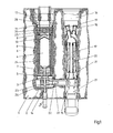
- a first cavern 2 is created, in which a reactor container 4 is arranged resting on a support ring 3.
- This basically consists of a metallic base plate 5, a likewise metallic jacket 6, a bottom 7, a side reflector 8 and a ceiling reflector 9, the latter three parts being made up only of graphite blocks with an outer layer of coal stones; by doing without metallic Some of them are able to withstand the elevated temperatures that occur in the event of accidents.
- the reactor vessel 4 contains a bed 10 of spherical fuel elements, the reactivity of which is regulated with the aid of control rods 11, which can be moved up and down in channels created for this purpose in the side reflector 8 with the aid of drive devices, not shown here.
- the drive devices are arranged over a cover 13 which closes the first cavern 2 towards the top. Spent fuel assemblies are withdrawn via a tube 14. The illustration of a corresponding addition device for fresh fuel elements at the upper end of the reactor vessel 4 has been omitted here for the sake of clarity.
- a steam generator 17 is arranged, in which the cooling gas heated in the fuel assembly 10 emits its heat. This is of conventional design with a water inlet 18, a steam outlet 19 and tube bundles 20 arranged between them and need not be described further.
- the circulation of the cooling gas is maintained by a fan 21 arranged below the steam generator 17.
- the gas routing in the first cavern 2 deserves special attention.
- the cooling gas guided through a connecting channel out of the second cavern 15 is guided specifically to the base plate 5 by guide devices 23, so that this is not exposed to any temperature that is not permitted for metallic materials. Openings are made in the base plate 5, which are aligned with further cooling channels 24 arranged in the side reflector 8. In these cooling channels, which limit the temperature in the Ensure side reflector, the gas is conducted in a collecting space 25 arranged above the ceiling reflector, from where it flows down through the fuel element 10. When heated up, it leaves the reactor vessel 4 through openings in the bottom 7 and collects in a collecting space 26, to which a hot gas line 27 leading to the steam generator 17 is connected. The connection between the collecting chamber 26 and hot gas line 27 can be released by remotely controlled tools ..
- FIG. 2 shows the state of the system after the reactor has been switched off with the aid of the control rods 11 and the fuel element fill 10 has been removed after the corresponding decay through the exhaust pipe 14. Then the cover 13 was removed together with the control rod drives arranged in it.
- the cooling lines 28 were separated at a suitable point, not shown here.
- the plugs 30 were removed and fastened in the cooling channels 24 to a cross member 32.
- Drawbars which were locked at their lower end in the base plate 5.
- FIG. 3 shows an alternative construction, the parts whose function corresponds to that shown in FIGS. 1 and 2 being given the same reference numerals.
- a steel pressure vessel is used here as the safety vessel 1, as is used in the same way for light-water-cooled nuclear reactors.
- An additional shield 34 made of concrete is required here for radiation shielding.
- the reactor and heat exchanger are arranged one above the other so that a second cavern can be dispensed with.
- the hot gas enters through very short lines 27 in the heat exchanger 17, which surrounds the fuel assembly exhaust pipe 14 in a ring shape. Between the two there is still an annular space in which the cooled gas flows into the space which here fulfills the function of the cavern 2, from where it takes the path through the reactor described above.
- the connections of the hot gas line 27 to the heat exchanger 17 are designed as plug connections. After loosening the lid 13, the switched-off and emptied reactor can be lifted out of the safety container 1 in the same way as that described above.
Landscapes
- Physics & Mathematics (AREA)
- Engineering & Computer Science (AREA)
- Plasma & Fusion (AREA)
- General Engineering & Computer Science (AREA)
- High Energy & Nuclear Physics (AREA)
- Structure Of Emergency Protection For Nuclear Reactors (AREA)
- Devices And Processes Conducted In The Presence Of Fluids And Solid Particles (AREA)
- Monitoring And Testing Of Nuclear Reactors (AREA)
Applications Claiming Priority (2)
| Application Number | Priority Date | Filing Date | Title |
|---|---|---|---|
| DE19803016402 DE3016402A1 (de) | 1980-04-29 | 1980-04-29 | Hochtemperaturreaktor in modul-bauweise |
| DE3016402 | 1980-04-29 |
Publications (2)
| Publication Number | Publication Date |
|---|---|
| EP0039016A1 true EP0039016A1 (fr) | 1981-11-04 |
| EP0039016B1 EP0039016B1 (fr) | 1984-09-12 |
Family
ID=6101182
Family Applications (1)
| Application Number | Title | Priority Date | Filing Date |
|---|---|---|---|
| EP81102959A Expired EP0039016B1 (fr) | 1980-04-29 | 1981-04-16 | Réacteur nucléaire à haute température en ensemble modulaire |
Country Status (5)
| Country | Link |
|---|---|
| US (1) | US4476089A (fr) |
| EP (1) | EP0039016B1 (fr) |
| JP (1) | JPS57582A (fr) |
| DE (2) | DE3016402A1 (fr) |
| ES (1) | ES501717A0 (fr) |
Cited By (2)
| Publication number | Priority date | Publication date | Assignee | Title |
|---|---|---|---|---|
| EP0095662A1 (fr) * | 1982-06-01 | 1983-12-07 | INTERATOM Gesellschaft mit beschränkter Haftung | Réacteur nucléaire à haute température avec conduit de gaz chaud qui est détachable de la cuve du réacteur |
| US4808370A (en) * | 1985-05-23 | 1989-02-28 | Interatom Gmbh | Connection of a hot gas line to the core barrel of a gas-cooled high-temperature nuclear reactor |
Families Citing this family (17)
| Publication number | Priority date | Publication date | Assignee | Title |
|---|---|---|---|---|
| DE3344527A1 (de) * | 1983-12-09 | 1985-06-20 | Hochtemperatur-Reaktorbau GmbH, 4600 Dortmund | Kernreaktoranlage |
| DE3345478A1 (de) * | 1983-12-15 | 1985-06-27 | INTERATOM GmbH, 5060 Bergisch Gladbach | Kernbehaelter fuer einen hochtemperatur-kernreaktor |
| DE3345457A1 (de) * | 1983-12-15 | 1985-06-27 | INTERATOM GmbH, 5060 Bergisch Gladbach | Behaeltersystem fuer einen hochtemperaturkernreaktor |
| DE3518968A1 (de) * | 1985-05-25 | 1986-11-27 | Hochtemperatur-Reaktorbau GmbH, 4600 Dortmund | Unterirdisch in der kaverne eines zylindrischen druckbehaelters angeordneter kernreaktor niedriger leistung |
| DE3519934A1 (de) * | 1985-06-04 | 1986-12-04 | Kernforschungsanlage Jülich GmbH, 5170 Jülich | Core fuer einen hochtemperatur-kernreaktor |
| DE3534422A1 (de) * | 1985-09-27 | 1987-04-09 | Hochtemperatur Reaktorbau Gmbh | Unterirdisch in der kaverne eines zylindrischen druckbehaelters angeordneter kernreaktor niedriger leistung |
| JPS62113191U (fr) * | 1986-04-28 | 1987-07-18 | ||
| JP2745766B2 (ja) * | 1990-03-26 | 1998-04-28 | 富士電機株式会社 | ペブルベッド型高温ガス炉 |
| DE4227795A1 (de) * | 1992-08-21 | 1994-02-24 | Siemens Ag | Kernreaktor-Brennstoffelement |
| US20050042149A1 (en) * | 1994-04-01 | 2005-02-24 | Integrated Chemical Synthesizers, Inc. | Nanoscale chemical synthesis |
| US5580523A (en) * | 1994-04-01 | 1996-12-03 | Bard; Allen J. | Integrated chemical synthesizers |
| US8681921B2 (en) * | 2009-03-30 | 2014-03-25 | Ge-Hitachi Nuclear Energy Americas, Llc | System for assembling or disassembling a segmented rod |
| CN101714413B (zh) * | 2009-12-23 | 2012-07-25 | 清华大学 | 高温气冷堆蒸汽发电系统及方法 |
| JP6001457B2 (ja) * | 2010-02-22 | 2016-10-05 | アドバンスト・リアクター・コンセプツ・エルエルシー | 長い燃料交換間隔を有する小型の高速中性子スペクトル原子力発電所の高速中性子スペクトル原子炉システム、原子力を提供する方法、及び、炉心の締め付けのためのシステム |
| JP5787709B2 (ja) * | 2011-10-14 | 2015-09-30 | 三菱重工業株式会社 | 高温ガス炉蒸気発電システム |
| WO2017165455A1 (fr) * | 2016-03-21 | 2017-09-28 | Rittmanic Matthew | Bâtiment à conteneur intermodal |
| CN113270205B (zh) * | 2021-03-29 | 2023-12-22 | 中国核电工程有限公司 | 一种模块化压力管式气冷微堆堆芯 |
Citations (7)
| Publication number | Priority date | Publication date | Assignee | Title |
|---|---|---|---|---|
| GB821607A (en) * | 1948-06-15 | 1959-10-14 | Atomic Energy Authority Uk | Improvements in or relating to nuclear reactors |
| DE1148827B (de) * | 1958-10-14 | 1963-05-16 | Atomic Energy Commission | Ventil zur Steuerung des Medienausflusses aus einem Behaelter |
| GB1036935A (en) * | 1962-08-04 | 1966-07-20 | Oesterr Studien Atomenergie | Improvements in or relating to nuclear reactors |
| DE1257297B (de) * | 1965-09-24 | 1967-12-28 | Sulzer Ag | Atomkernreaktoranlage mit mehreren parallel geschalteten Umwaelzgeblaesen mit Diffusoren |
| FR2114258A5 (en) * | 1970-11-20 | 1972-06-30 | Edf | Nuclear reactor for indirect heating cycle - with heat exchange chamber at lower pressure than core chamber |
| FR2132572A1 (en) * | 1971-04-09 | 1972-11-24 | Commissariat Energie Atomique | Gas cooled reactor - with core and primary coolant circuit incorporated in concrete pressure vessel |
| FR2292314A1 (fr) * | 1974-11-23 | 1976-06-18 | Hochtemperatur Reaktorbau Gmbh | Installation pour la production de la chaleur necessaire a un traitement, comprenant plusieurs chambres de reaction chauffees par le gaz de refroidissement d'un reacteur a haute temperature |
Family Cites Families (8)
| Publication number | Priority date | Publication date | Assignee | Title |
|---|---|---|---|---|
| DE1433201B2 (de) * | 1962-11-08 | 1971-11-11 | Deutsche Texaco Ag, 2000 Hamburg | Einrichtung und Verfahren zur Behandlung von Bitumina mit Wärme- und Strahlungsenergie mittels eines in einer Bohrung angeordneten Atomreaktors sowie Verfahren zur Strahlenabsicherung und Wärmeisolierung der Einrichtung |
| GB1204314A (en) * | 1966-09-21 | 1970-09-03 | Atomic Energy Authority Uk | Improvements in or relating to nuclear reactors |
| FR2134074B1 (fr) * | 1970-08-05 | 1973-12-21 | Electricite De France | |
| DE2241426C3 (de) * | 1972-08-23 | 1980-12-04 | Hochtemperatur-Reaktorbau Gmbh, 5000 Koeln | Kernkraftwerk mit geschlossenem, mehrsträngig ausgeführtem Gaskühlkreislauf |
| US4000038A (en) * | 1974-04-11 | 1976-12-28 | Brown Boveri-Sulzer Turbomaschinen Aktiengesellschaft | Nuclear power station |
| FR2361616A1 (fr) * | 1976-08-12 | 1978-03-10 | Ght Hochtemperaturreak Tech | Recipient soumis a des temperatures elevees et variables, en particulier recipient de reacteurs a boulets |
| DE2718493C2 (de) * | 1977-04-26 | 1987-05-07 | Hochtemperatur-Reaktorbau GmbH, 4600 Dortmund | Tragvorrichtung für einen Kern eines gasgekühlten Hochtemperaturreaktors großer Leistung |
| DE2817540A1 (de) * | 1978-04-21 | 1979-10-25 | Hochtemperatur Reaktorbau Gmbh | Deckenreflektor fuer einen gasgekuehlten kugelhaufenreaktor und verfahren zum ausbau des deckenreflektors |
-
1980
- 1980-04-29 DE DE19803016402 patent/DE3016402A1/de not_active Withdrawn
-
1981
- 1981-04-16 EP EP81102959A patent/EP0039016B1/fr not_active Expired
- 1981-04-16 DE DE8181102959T patent/DE3165941D1/de not_active Expired
- 1981-04-28 ES ES501717A patent/ES501717A0/es active Granted
- 1981-04-28 JP JP6512081A patent/JPS57582A/ja active Granted
- 1981-07-02 US US06/280,092 patent/US4476089A/en not_active Expired - Fee Related
Patent Citations (7)
| Publication number | Priority date | Publication date | Assignee | Title |
|---|---|---|---|---|
| GB821607A (en) * | 1948-06-15 | 1959-10-14 | Atomic Energy Authority Uk | Improvements in or relating to nuclear reactors |
| DE1148827B (de) * | 1958-10-14 | 1963-05-16 | Atomic Energy Commission | Ventil zur Steuerung des Medienausflusses aus einem Behaelter |
| GB1036935A (en) * | 1962-08-04 | 1966-07-20 | Oesterr Studien Atomenergie | Improvements in or relating to nuclear reactors |
| DE1257297B (de) * | 1965-09-24 | 1967-12-28 | Sulzer Ag | Atomkernreaktoranlage mit mehreren parallel geschalteten Umwaelzgeblaesen mit Diffusoren |
| FR2114258A5 (en) * | 1970-11-20 | 1972-06-30 | Edf | Nuclear reactor for indirect heating cycle - with heat exchange chamber at lower pressure than core chamber |
| FR2132572A1 (en) * | 1971-04-09 | 1972-11-24 | Commissariat Energie Atomique | Gas cooled reactor - with core and primary coolant circuit incorporated in concrete pressure vessel |
| FR2292314A1 (fr) * | 1974-11-23 | 1976-06-18 | Hochtemperatur Reaktorbau Gmbh | Installation pour la production de la chaleur necessaire a un traitement, comprenant plusieurs chambres de reaction chauffees par le gaz de refroidissement d'un reacteur a haute temperature |
Non-Patent Citations (2)
| Title |
|---|
| Energie Nucleaire, Band 9, Nr. 6, Oktober 1967, seiten 358-372 Rueil - Malmaison, FR. L. VALETTE et al.: "Les Reacteurs a Haute Temperature en Europe" * abbildung 8a * * |
| The Journal of the British Nuclear Energy Society, Band 5, Nr. 3, Juli 1966, seiten 319-331 London, G.B. H.W. MULLER et al.: "The AVR Pebble Bed Reactor" * abbildung 1 * * |
Cited By (2)
| Publication number | Priority date | Publication date | Assignee | Title |
|---|---|---|---|---|
| EP0095662A1 (fr) * | 1982-06-01 | 1983-12-07 | INTERATOM Gesellschaft mit beschränkter Haftung | Réacteur nucléaire à haute température avec conduit de gaz chaud qui est détachable de la cuve du réacteur |
| US4808370A (en) * | 1985-05-23 | 1989-02-28 | Interatom Gmbh | Connection of a hot gas line to the core barrel of a gas-cooled high-temperature nuclear reactor |
Also Published As
| Publication number | Publication date |
|---|---|
| EP0039016B1 (fr) | 1984-09-12 |
| ES8202976A1 (es) | 1982-02-16 |
| JPS6364755B2 (fr) | 1988-12-13 |
| ES501717A0 (es) | 1982-02-16 |
| DE3165941D1 (en) | 1984-10-18 |
| DE3016402A1 (de) | 1981-11-05 |
| JPS57582A (en) | 1982-01-05 |
| US4476089A (en) | 1984-10-09 |
Similar Documents
| Publication | Publication Date | Title |
|---|---|---|
| EP0039016B1 (fr) | Réacteur nucléaire à haute température en ensemble modulaire | |
| DE3518968C2 (fr) | ||
| DE1228352B (de) | Kernreaktor | |
| DE69010977T2 (de) | Indirektes passives Kühlsystem für Kernreaktoren mit Flüssigmetallkühlung. | |
| DE3345113A1 (de) | Kernkraftwerk mit einem ht-kleinreaktor | |
| EP0036166B1 (fr) | Réacteur à haute température | |
| DE3141892C2 (de) | Kernreaktoranlage | |
| CH672965A5 (fr) | ||
| DE1957701A1 (de) | Steuersystem fuer Kernreaktoren | |
| DE3534422C2 (fr) | ||
| DE2455508C2 (de) | Vorrichtung zum Erzeugen von Synthesegas durch Ausnutzen der in einem gasgekühlten Hochtemperaturreaktor gewonnenen Wärmeenergie | |
| DE2411039C2 (de) | Kernkraftwerk mit geschlossenem Gaskühlkreislauf zur Erzeugung von Prozeßwärme | |
| DE3047959C2 (fr) | ||
| DE1439773A1 (de) | Einheit fuer den aktiven Kern eines Kernreaktors | |
| CH689240A5 (de) | Kernrohr- und Tragplattenbaueinheit fuer Druckwasserkernreaktor. | |
| DE3212266C1 (de) | Kernreaktoranlage | |
| CH672207A5 (fr) | ||
| DE2404843C2 (de) | Kernkraftwerk mit geschlossenem Gaskühlkreislauf | |
| DE2455507C2 (de) | Prozeßwärmeanlage zur Erzeugung von Wasserstoff mit Hilfe der Wärme aus einem Hochtemperaturreaktor | |
| DE2650922C2 (de) | Wärmetauscher zur Übertragung von in einem Hochtemperaturreaktor erzeugter Wärme an ein Zwischenkreislaufgas | |
| DE3141734A1 (de) | Kernreaktor mit einem gasgekuehlten kugelhaufen-kernreaktor | |
| DE1589848B1 (de) | Atomkernreaktor mit Spannbeton-Druckbehaelter | |
| DE3212264A1 (de) | Anlage zur nuklearen erzeugung von waerme und zu deren weiterverwendung in waermeaufnehmenden apparaten | |
| DE1272463B (de) | Thermischer Kernreaktor | |
| DE2506293C2 (de) | Hochtemperaturreaktor mit geschlossenem Gaskühlkreislauf |
Legal Events
| Date | Code | Title | Description |
|---|---|---|---|
| PUAI | Public reference made under article 153(3) epc to a published international application that has entered the european phase |
Free format text: ORIGINAL CODE: 0009012 |
|
| AK | Designated contracting states |
Designated state(s): BE CH DE FR GB NL SE |
|
| 17P | Request for examination filed |
Effective date: 19810914 |
|
| GRAA | (expected) grant |
Free format text: ORIGINAL CODE: 0009210 |
|
| AK | Designated contracting states |
Designated state(s): BE CH DE FR GB LI NL SE |
|
| REF | Corresponds to: |
Ref document number: 3165941 Country of ref document: DE Date of ref document: 19841018 |
|
| ET | Fr: translation filed | ||
| PLBE | No opposition filed within time limit |
Free format text: ORIGINAL CODE: 0009261 |
|
| STAA | Information on the status of an ep patent application or granted ep patent |
Free format text: STATUS: NO OPPOSITION FILED WITHIN TIME LIMIT |
|
| 26N | No opposition filed | ||
| PGFP | Annual fee paid to national office [announced via postgrant information from national office to epo] |
Ref country code: BE Payment date: 19920428 Year of fee payment: 12 |
|
| PGFP | Annual fee paid to national office [announced via postgrant information from national office to epo] |
Ref country code: SE Payment date: 19920429 Year of fee payment: 12 |
|
| PGFP | Annual fee paid to national office [announced via postgrant information from national office to epo] |
Ref country code: NL Payment date: 19920430 Year of fee payment: 12 |
|
| PGFP | Annual fee paid to national office [announced via postgrant information from national office to epo] |
Ref country code: CH Payment date: 19920723 Year of fee payment: 12 |
|
| PG25 | Lapsed in a contracting state [announced via postgrant information from national office to epo] |
Ref country code: SE Effective date: 19930417 |
|
| PG25 | Lapsed in a contracting state [announced via postgrant information from national office to epo] |
Ref country code: LI Effective date: 19930430 Ref country code: CH Effective date: 19930430 Ref country code: BE Effective date: 19930430 |
|
| BERE | Be: lapsed |
Owner name: GHT-G. FUR HOCHTEMPERATURREAKTOR-TECHNIK M.B.H. Effective date: 19930430 |
|
| PG25 | Lapsed in a contracting state [announced via postgrant information from national office to epo] |
Ref country code: NL Effective date: 19931101 |
|
| NLV4 | Nl: lapsed or anulled due to non-payment of the annual fee | ||
| REG | Reference to a national code |
Ref country code: CH Ref legal event code: PL |
|
| PGFP | Annual fee paid to national office [announced via postgrant information from national office to epo] |
Ref country code: GB Payment date: 19940314 Year of fee payment: 14 |
|
| PGFP | Annual fee paid to national office [announced via postgrant information from national office to epo] |
Ref country code: FR Payment date: 19940425 Year of fee payment: 14 |
|
| PGFP | Annual fee paid to national office [announced via postgrant information from national office to epo] |
Ref country code: DE Payment date: 19940620 Year of fee payment: 14 |
|
| EUG | Se: european patent has lapsed |
Ref document number: 81102959.4 Effective date: 19931110 |
|
| PG25 | Lapsed in a contracting state [announced via postgrant information from national office to epo] |
Ref country code: GB Effective date: 19950416 |
|
| GBPC | Gb: european patent ceased through non-payment of renewal fee |
Effective date: 19950416 |
|
| PG25 | Lapsed in a contracting state [announced via postgrant information from national office to epo] |
Ref country code: FR Effective date: 19951229 |
|
| PG25 | Lapsed in a contracting state [announced via postgrant information from national office to epo] |
Ref country code: DE Effective date: 19960103 |
|
| REG | Reference to a national code |
Ref country code: FR Ref legal event code: ST |