EP0039056A1 - Procédé et appareil pour produire des emballages en pellicules sous vide - Google Patents
Procédé et appareil pour produire des emballages en pellicules sous vide Download PDFInfo
- Publication number
- EP0039056A1 EP0039056A1 EP81103098A EP81103098A EP0039056A1 EP 0039056 A1 EP0039056 A1 EP 0039056A1 EP 81103098 A EP81103098 A EP 81103098A EP 81103098 A EP81103098 A EP 81103098A EP 0039056 A1 EP0039056 A1 EP 0039056A1
- Authority
- EP
- European Patent Office
- Prior art keywords
- web
- vacuum chamber
- lower web
- upper web
- packaged goods
- Prior art date
- Legal status (The legal status is an assumption and is not a legal conclusion. Google has not performed a legal analysis and makes no representation as to the accuracy of the status listed.)
- Granted
Links
- 238000000034 method Methods 0.000 title claims abstract description 18
- 238000007789 sealing Methods 0.000 claims abstract description 69
- 238000010438 heat treatment Methods 0.000 claims abstract description 27
- 238000009461 vacuum packaging Methods 0.000 claims abstract description 5
- 229920001971 elastomer Polymers 0.000 claims description 16
- 230000001154 acute effect Effects 0.000 claims description 4
- 229920001169 thermoplastic Polymers 0.000 abstract description 4
- 239000004416 thermosoftening plastic Substances 0.000 abstract description 4
- 210000003323 beak Anatomy 0.000 description 8
- 239000000463 material Substances 0.000 description 6
- 239000004033 plastic Substances 0.000 description 6
- 239000004744 fabric Substances 0.000 description 3
- 239000011888 foil Substances 0.000 description 3
- 238000004806 packaging method and process Methods 0.000 description 3
- 238000005192 partition Methods 0.000 description 3
- 238000007665 sagging Methods 0.000 description 3
- 238000009460 vacuum skin packaging Methods 0.000 description 3
- 229920003182 Surlyn® Polymers 0.000 description 2
- 230000015572 biosynthetic process Effects 0.000 description 2
- 230000006835 compression Effects 0.000 description 2
- 238000007906 compression Methods 0.000 description 2
- 235000013305 food Nutrition 0.000 description 2
- 239000011521 glass Substances 0.000 description 2
- 239000012815 thermoplastic material Substances 0.000 description 2
- 230000006978 adaptation Effects 0.000 description 1
- QVGXLLKOCUKJST-UHFFFAOYSA-N atomic oxygen Chemical compound [O] QVGXLLKOCUKJST-UHFFFAOYSA-N 0.000 description 1
- 239000011248 coating agent Substances 0.000 description 1
- 238000000576 coating method Methods 0.000 description 1
- 239000012141 concentrate Substances 0.000 description 1
- 238000010924 continuous production Methods 0.000 description 1
- 238000001816 cooling Methods 0.000 description 1
- 229920001038 ethylene copolymer Polymers 0.000 description 1
- 238000000605 extraction Methods 0.000 description 1
- 229920000554 ionomer Polymers 0.000 description 1
- 238000004519 manufacturing process Methods 0.000 description 1
- 229910052760 oxygen Inorganic materials 0.000 description 1
- 239000001301 oxygen Substances 0.000 description 1
- 239000004810 polytetrafluoroethylene Substances 0.000 description 1
- 229920001343 polytetrafluoroethylene Polymers 0.000 description 1
- 230000002028 premature Effects 0.000 description 1
- 238000003825 pressing Methods 0.000 description 1
- 239000010453 quartz Substances 0.000 description 1
- 230000005855 radiation Effects 0.000 description 1
- 229920005989 resin Polymers 0.000 description 1
- 239000011347 resin Substances 0.000 description 1
- VYPSYNLAJGMNEJ-UHFFFAOYSA-N silicon dioxide Inorganic materials O=[Si]=O VYPSYNLAJGMNEJ-UHFFFAOYSA-N 0.000 description 1
- 229920002379 silicone rubber Polymers 0.000 description 1
- 239000004945 silicone rubber Substances 0.000 description 1
- 238000009466 skin packaging Methods 0.000 description 1
- 238000003466 welding Methods 0.000 description 1
- 230000037303 wrinkles Effects 0.000 description 1
Images




Classifications
-
- B—PERFORMING OPERATIONS; TRANSPORTING
- B65—CONVEYING; PACKING; STORING; HANDLING THIN OR FILAMENTARY MATERIAL
- B65B—MACHINES, APPARATUS OR DEVICES FOR, OR METHODS OF, PACKAGING ARTICLES OR MATERIALS; UNPACKING
- B65B11/00—Wrapping, e.g. partially or wholly enclosing, articles or quantities of material, in strips, sheets or blanks, of flexible material
- B65B11/50—Enclosing articles, or quantities of material, by disposing contents between two sheets, e.g. pocketed sheets, and securing their opposed free margins
- B65B11/52—Enclosing articles, or quantities of material, by disposing contents between two sheets, e.g. pocketed sheets, and securing their opposed free margins one sheet being rendered plastic, e.g. by heating, and forced by fluid pressure, e.g. vacuum, into engagement with the other sheet and contents, e.g. skin-, blister-, or bubble- packaging
Definitions
- the invention relates to a method and a device for producing vacuum skin packaging according to the preamble of claim 1 and claim 4.
- the invention has for its object to provide a method by which an airtight skin Ver even with packaged goods of great height Pack can be made, and to provide an apparatus for performing the method.
- contour sealing makes better use of the size of the webs, ie the packaged goods can be larger in relation to the dimensions of the webs be than in pure F lächenêtelung. While there must be an edge of at least 20 mm around the packaged goods for surface sealing, it is sufficient in the method according to the invention to provide an edge of about 10 mm.
- the time required for a packaging cycle can be reduced by preheating the top web before loading the packaged goods. In a cyclical process, this preheating can take place while the previous skin packaging is being produced.
- the heating of the lower web can take place during the extraction of air between the webs.
- air pressure is preferably first applied to the upper web and then to the lower web on the side facing away from the packaged goods in order to counter the webs To press packaged goods.
- the web it is advisable not only to guide the top web, but also the bottom web, through conveyor chains at the lateral edges.
- the lower web is guided right up to the vacuum chamber.
- the vacuum skin packaging is moved out of the vacuum chamber by the guide chain of the upper web and thereby pulls the lower web. If the lower web is guided through its own guide chains right up to the vacuum chamber, only little force is exerted on the sealing seams by the redrawn lower web.
- the air between the webs is drawn off in the vacuum chamber. Precautions must be taken to ensure that the webs do not touch and stick together when they are introduced into the vacuum chamber. This is preferably achieved by the webs entering the vacuum chamber at an acute angle to one another and only touching at the end of the vacuum chamber.
- a height-adjustable sealing plate is preferably arranged in the lower part of the vacuum chamber.After closing the vacuum chamber, it is initially in its deep position of a few millimeters below the opening edge of the lower part, so that a corresponding gap remains between the webs through which the air can be extracted. After the air has been drawn off and approximately at the same time as the outside air has been let into the upper part, the sealing plate is raised and seals the two webs between itself and the sealing rubber at the opening edge of the upper part. So that the packaged goods run smoothly into the vacuum chamber on the lower web, a fabric band is preferably stretched over the lower part, which supports the lower web on its way through the vacuum chamber and prevents the lower web and the packaged goods lying directly on the heated sealing plate.
- the guide chain links are deflected downwards by chain wheels.
- the driver tabs are preferably tilted away to the side so that they cannot come into contact with the side edges of the lower web when the conveyor chains are deflected.
- the sideways tilting of the carrier plates is achieved in that the carrier plates run onto a conical lifting ring arranged centrally to the chain wheel.
- the packaging consists of an upper web 1 and a lower web 2, which are sealed together.
- the webs consist of thermoplastic films, in particular films of thermoplastic ionomer resins based on crosslinked ethylene copolymers, as are known under the trade name Surlyn.
- the lower web 2 can, however, also consist of cardboard or another rigid material which has a coating of a thermoplastic material and is therefore heat-sealable with the upper web 1.
- the sealing of the webs consists of a surface sealing and an additional sealing produced by pressure and heat in a narrow edge strip 20, which is referred to here as contour sealing.
- Such folds 21 are sealed at the edge of the pack by the additional contour sealing.
- the vacuum skin pack is produced in such a way that the packaged goods 5 are placed on the lower web 2 and the already pre-heated upper web 1 above the packaged goods 5 is arranged.
- the air is drawn off between the webs and around the packaged goods 5 and at the same time the lower web 2 is heated to the extent that it is plastic.
- the contour is then sealed by mechanical pressure in the narrow edge strip 20 and the top web 1 is placed against the packaged goods 5 and against the bottom web 2 by air pressure on the outside of the top web 1.
- the edge strip 20 extends around the entire package.
- the pack 3 can then be separated from the webs and any edge parts of the webs outside the edge strip 20 can be cut off.
- top web 1 and the bottom web 2 are heated and the pressure exerted on the edge strip 20 depend on the film material and its thickness.
- the top web is heated to a temperature of about 100 ° C and the bottom web is heated by contact with a sealing plate heated to about 90 ° C.
- the pressure exerted in the edge strip 20 is of the order of magnitude of 200 N / cm 2 . This pressure is applied for about 1 second.
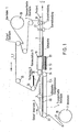
- the lower web 2 is guided laterally by guide chains 4 over a table 22 on which the packaged goods 5 are placed onto the lower web 2 by hand or mechanically.
- the guide chains 4 run around sprockets 23, 24 at the beginning and at the end of the table 22.
- the lower web 2 is unwound from a supply roll 26 and at the beginning of the table 22 ordered sprocket 23 captured by clamping members 27 of the guide chain 4. The clamping members 27 and their operation will be described later in detail.
- the upper web 1 is unwound from a supply roll 26 by a guide chain 7 with the same clamping members 27 as the guide chain 4 and passed under a preheating station 8, in which the upper web 1 is heated to such an extent that it is plastic. After the preheating station 8, the upper web 1 runs into a vacuum chamber 9. The upper web 1 is also guided through the vacuum chain 9 and then through the guide chain 7 until the vacuum pack is dispensed. The upper web 1 must therefore be wider than the vacuum chamber 9, since the guide chain 7 does not pass through the vacuum chamber 9, but laterally past it.
- the lower web 2 is released at the sprocket 24 arranged directly in front of the vacuum chamber 9 and the lower web 2 is taken behind the sprocket 24 by the upper web 1, starting from the point where both webs are sealed together.
- thermoplastic materials used for the web have a very low mechanical strength when warm, so that there is a risk that the bottom web 2 will tear or the top web 1 will be separated along its two guide chains 7.
- the vacuum chamber 9 consists of a raised and lowered upper part 10 and a stationary lower part 11.
- the upper part 10 is box-shaped and is open at the bottom.
- a sealing rubber 14 is attached to the horizontal part of the opening edge.
- the lower part 11 has a recess for a sealing plate 12 which can be raised and lowered by hydraulic or pneumatic devices.
- the sealing plate 12 is heated on its entire upper side, in particular also in the edge regions, since the edge regions of the lower web 2 must have a sufficiently high temperature to produce the contour sealing in order to make the material plastic and sealable. There is only a small gap of a few millimeters between the sealing plate 12 and the edge of the recess in the lower part 11.
- the upper side thereof In the lowered position of the sealing plate 12, the upper side thereof is located a few millimeters, preferably 8 mm, below the opening edge of the lower part 11. In its raised position, the sealing plate 12 presses against the sealing rubber 14 and the contour sealing of the two foils is thereby produced between the two.
- the width and length dimensions of the sealing plate 12 must therefore be somewhat larger, namely by the width of the edge strip 20 of the contour seal, than the clear width and the clear length of the open underside of the upper part 10.
- the dimension transverse to the direction of transport and below is defined here as width Length understood the dimension along the transport direction of the two tracks.
- the inside dimensions of the recess in the lower part 11 lie approximately in the middle between the inner and outer dimensions of the opening edge of the upper part 10, so that the outer part of the sealing rubber 14 rests against the opening edge of the recess of the lower part 11 and acts as a seal.
- the sealing rubber 14 preferably has a structure as shown in FIG. 12.
- the structuring on the one hand ensures that the two webs are sealed together with high pressure and on the other hand it is avoided that the top web 1 sticks to the sealing rubber 14.
- the structuring can, for example, be grid-shaped, so that the surface is waffle-patterned.
- a suitable material for the sealing rubber 14 is silicone rubber with a Shore hardness of approx. 70 °.
- the sealing rubber 14 can be connected to the upper part 10, for example, in that it has a T-shaped profile which is inserted into a corresponding groove in the upper part 10.
- the vacuum pack is produced in the vacuum chamber 9.
- the upper part 10 is first raised to such an extent that the lower web 2 with the packaged goods 5 arranged thereon and the preheated upper web 1 arranged above it can enter the open vacuum chamber 9.
- the transport takes place through the guide chain 7 of the upper web 1.
- the vacuum chamber 9 is then closed, that is to say the upper part 10 is placed on the lower part 11, the outer part of the sealing rubber 14 acting as a seal.
- the upper web 1, which is wider than the vacuum chamber 9, is clamped between the sealing rubber 14 and the opening edge of the lower part 11.
- the lower web 2 is approximately as wide as the sealing plate 12 and must in any case be wider than the opening of the upper part 10 and narrower than the recess in the lower part 11.
- the lower web 2 is thereby clamped only at the front and rear ends of the vacuum chamber 9, but not laterally.
- the top web 1 is stretched over the packaged goods 5 in a tent-like manner.
- the air is sucked out of the lower part 11 and thus also around the packaged goods 5, for example through a line attached to the underside of the recess in the lower part 11.
- the sealing plate 12 is still in its lowered position, so that a gap remains between the upper web 1 and the lower web 2 within the vacuum chamber 9, through which the air around the packaged goods 5 can be sucked off.
- the gap between the recess in the lower part 11 and the sealing plate 12 is also dimensioned such that the air can be sucked out through it.
- the upper part 10 In the closed state of the vacuum chamber 9, the upper part 10 is sealed airtight from the lower part 11 by the upper web 1. In order to obtain pressure equalization when the lower part 11 is evacuated, the upper part 10 is therefore also evacuated at the same time.
- the lower web 2 is heated and made plastic by heating devices in the sealing plate 12.
- the sealing plate 12 is pressed upwards against the sealing rubber 14 by hydraulic or pneumatic devices, preferably by compressed air cushions 13. This creates the contour seal between the two webs and seals the package.
- the upper part 10 of the vacuum chamber 9 is ventilated, so that the atmospheric pressure that builds up applies the heated, plastic top film to the packaged goods 5 and thus forms the package. Due to the still existing negative pressure in the lower part 11, both webs in the part surrounding the packaged goods 5 are pressed together against the sealing plate 12, whereby the surface sealing occurs, in which both webs are welded on the entire surface around the packaged goods 5.
- the vacuum chamber 9 can be opened, for which purpose the lower part 11 is expediently ventilated beforehand.
- the finished vacuum pack can then be pulled out of the vacuum chamber 9 by the upper web 1, which is still held laterally by its guide chain, while at the same time the part of the upper web 1 and the lower web 2 required for producing the next vacuum pack with the next packaged goods 5 arranged thereon into the vacuum chamber 9 to be pulled.
- the finished vacuum pack 3 first reaches a cooling plate 29 and then into a device 30 in which the vacuum. Pack 3 is cut in the longitudinal and transverse directions from the top web 1 and the bottom web 2. Up to this device 30, the vacuum pack is transported by the guide chain 7.
- a separating device which prevents the lower web 2 from sticking, is expediently arranged above the lower part 11 of the vacuum chamber 9.
- a heat-resistant and friction-reducing can be used as a separating device Band be stretched over the lower part 11, which is fixed by springs 31 on one or both sides of the lower part 11.
- the tape is preferably a PTFE-coated glass fabric tape 15. The tension in the glass fabric tape 15 is sufficient to hold the packaged goods 5 and to prevent the lower web 2 with the packaged goods 5 thereon from entering the opened vacuum chamber 9, to which When the sealing plate 12 is still in its lowered state, it lies directly on the sealing plate 12.
- a device for further heating the upper web 1 can also be provided in the upper part 10 of the vacuum chamber 9.
- the vacuum chamber 9 can be divided by partitions 32 in the upper part 10.
- a sealing rubber 14 is again provided on the underside of the partition or partitions 32. In this way, several vacuum packs 3 can be produced simultaneously in a single vacuum chamber 9.
- FIGS. 6 and 7 show two ways in which the top web 1 can be guided in order to prevent it from coming into contact with the bottom web 2 and sticking to it when it enters the open vacuum chamber 9. 6, such sticking is prevented by the fact that the guide chain 7 of the upper track 1 is guided through the last sprocket 25 arranged in front of the vacuum chamber at an acute angle to the lower web 2 and to the plane of the opening of the lower part 11 of the vacuum chamber 9.
- the acute angle is approximately such that the top web 1 runs in at the inlet end of the vacuum chamber 9 about 6 mm above the bottom web 2. This ensures that the two webs do not stick together prematurely and that there is a sufficient evacuation gap between the two webs after the vacuum chamber 9 has been closed.
- FIG. 7 Here, the upper web 1 is raised approximately 6 mm in the entire area of the vacuum chamber 9. This increase is exaggerated in Fig. 7. When the vacuum chamber 9 is closed, the upper web 1 is then pressed down onto the edge of the lower part 11 of the vacuum chamber 9.
- the sealing plate 12 in the lower part 11 of the vacuum chamber 9 is heated electrically. Due to the contact of the sealing plate 12 with the other parts of the vacuum chamber and due to radiation, there is a risk that the lower part 11 is heated so much overall that the webs stick to it. To one. To avoid such uncontrolled heating of the lower part 11, the opening edge of the lower part 11 is preferably water-cooled.
- any folds 21 in the top web 1 are sealed by the contour sealing, but for trouble-free operation of the device it is expedient to take measures which already prevent the formation of such folds 21.
- One of the measures taken for this is that, as already mentioned, the lower web 2 is transported to the vacuum chamber 9 by a guide chain 4.
- the guide chains 4, 7 consist of a chain 33, for example a Gall chain or a socket chain.
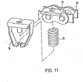
- the outer link plates are designed as angles 34, which carry a drive plate 16 and a helical compression spring 35.
- the horizontal part of the angle 34 forms, together with the driving flap 16, a beak which holds the upper web 1 or the lower web 2.
- the main part of the driving plate 16 is located above the angle 34 and is pressed against it by the helical compression spring 35, which is located on the opposite, lower side of the angle 34.
- the beak 16 opens by pressing against the driving plate 16 from below clears the way. The beak is opened not only when gripping and releasing a web, but also expediently when the guide chains 4, 7 are deflected around chain wheels 23, 24, 25.
- the beaks are offset in height in relation to the pins of the chain links, the beaks describe a larger path when the chains are deflected than the chain links themselves, so that the tracks also have to describe a larger path when deflecting around chain wheels and are therefore tensioned.
- the beaks are preferably opened in the area of the chain wheels 23, 24, 25. This is done by rings or disks 17 arranged centrally or eccentrically to the sprockets 23, 24, 25.
- the eccentric rings or disks 17 are arranged in such a way that the beaks open as early as possible so that the tension and elongation of the web are as large as possible Route distributed.
- Another difficulty associated with the guide chain 4 for the lower web 2 is that when the lower web 2 is released by the chain wheel 24 arranged in front of the vacuum chamber 9, the clamping members can readily release the lower web in the manner described, but the opened clamping members then be guided down around the sprocket 24. There is a risk that the raised driver flap 16 will cross the path of the lower web 2 and tear it down.
- the driver plates in the area of the sprocket 24 are not only raised as shown in FIG. 9, but at the same time tilted to the side, so that the distance between the driver plates of the two sides of the lower web 2 extends Guide chains 4 are enlarged and become larger than the width of the lower web 2.
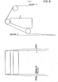
- the distance between the guide chains 7 is preferably increased in order to keep the top web 1 as taut as possible and to prevent sagging of the top web 1 heated in the preheating station 8. If the top web 1 were to sag when it entered the vacuum chamber 9, this would favor the formation of folds when the packaged goods 5 were stretched. This is shown in detail in FIG. 8.
- the distance between the chain wheels 25 after the preheating station 8 is a total of about 5 mm greater than the distance between the chain wheels 25 before the preheating station 8, that is to say the width of the top web 1 is expanded by about 5 mm .
- the extent of the stretch naturally depends on the material, the thickness and the width of the top web 1 and the temperature to which the top web 1 is heated by the preheating station 8.
- the upper web 1 can be heated by contact with a heating plate, by infrared radiators or by hot air.
- a heating plate has the disadvantage that when the length of the upper web 1 to be heated is changed, the heating plate must either be replaced or partially covered. Different heating of individual zones is difficult to achieve, moreover, the upper web 1 must be brought into contact with the heating plate either by vacuum or by compressed air, which increases the mechanical structure.
- a radiator array is therefore preferably composed of individual heating elements 40, as shown in FIG. 4.
- the heating elements 40 run transversely to the direction of travel of the web.
- several of the heating elements 40 can be switched off individually.
- heating elements 40 of different power can be used.
- the power of the individual heating elements 40 can also be controlled, for example, by triacs.
- the entire radiator field formed by the heating elements 40 can be adjusted in the longitudinal direction with respect to the vacuum chamber 9.
- the vacuum chamber is preferably designed to be exchangeable, so that it can be replaced with another vacuum chamber with larger or smaller dimensions in a few simple steps.
- the length of the top and bottom web fed per cycle is controlled according to the longitudinal dimension of the vacuum chamber.
- the design of the heating device with several separately controllable heating elements 40, the interchangeability of the vacuum chamber and the control of the feed length of the top and bottom webs together lead to an optimal adaptation of the respective pack to the packaged goods.
Landscapes
- Physics & Mathematics (AREA)
- Fluid Mechanics (AREA)
- Engineering & Computer Science (AREA)
- Mechanical Engineering (AREA)
- Vacuum Packaging (AREA)
- Containers And Plastic Fillers For Packaging (AREA)
Priority Applications (1)
| Application Number | Priority Date | Filing Date | Title |
|---|---|---|---|
| AT81103098T ATE14555T1 (de) | 1980-04-24 | 1981-04-24 | Verfahren und vorrichtung zum herstellen von vakuum-skin-verpackungen. |
Applications Claiming Priority (2)
| Application Number | Priority Date | Filing Date | Title |
|---|---|---|---|
| DE3015847 | 1980-04-24 | ||
| DE3015847A DE3015847C2 (de) | 1980-04-24 | 1980-04-24 | Verfahren zum Vakuum-Skinverpacken von verhältnismäßig hohem Packgut und Vorrichtung zur Durchführung des Verfahrens |
Publications (3)
| Publication Number | Publication Date |
|---|---|
| EP0039056A1 true EP0039056A1 (fr) | 1981-11-04 |
| EP0039056B1 EP0039056B1 (fr) | 1985-07-31 |
| EP0039056B2 EP0039056B2 (fr) | 1991-10-23 |
Family
ID=6100868
Family Applications (1)
| Application Number | Title | Priority Date | Filing Date |
|---|---|---|---|
| EP81103098A Expired - Lifetime EP0039056B2 (fr) | 1980-04-24 | 1981-04-24 | Procédé et appareil pour produire des emballages en pellicules sous vide |
Country Status (4)
| Country | Link |
|---|---|
| EP (1) | EP0039056B2 (fr) |
| JP (1) | JPS5737508A (fr) |
| AT (1) | ATE14555T1 (fr) |
| DE (1) | DE3015847C2 (fr) |
Cited By (7)
| Publication number | Priority date | Publication date | Assignee | Title |
|---|---|---|---|---|
| EP0126878A1 (fr) * | 1983-04-28 | 1984-12-05 | Multivac Sepp Haggenmüller Kg | Dispositif de transport pour guider une bande dans une machine d'emballage |
| WO1985003487A1 (fr) * | 1984-02-08 | 1985-08-15 | Multivac Sepp Haggenmüller Kg | Emballeuse avec une station de scellement |
| US4826065A (en) * | 1983-04-28 | 1989-05-02 | Multivac Sepp Haggenmuller Kg | Feeding means for feeding a machine web in a packaging machine |
| EP0582461A1 (fr) * | 1992-08-06 | 1994-02-09 | Idemitsu Petrochemical Co. Ltd. | Procédé et dispositif pour soudure à chaud les récipients |
| US7478662B2 (en) | 2004-10-09 | 2009-01-20 | Uhlmann Pac-Systeme Gmbh & Co. Kg | Apparatus for sealing foils to each other |
| US9119450B2 (en) | 2012-12-21 | 2015-09-01 | Novartis Ag | Contact lens package |
| WO2020058278A3 (fr) * | 2018-09-17 | 2020-05-28 | Gea Food Solutions Germany Gmbh | Machine d'emballage destinée à fabriquer un emballage à revêtement plat |
Families Citing this family (1)
| Publication number | Priority date | Publication date | Assignee | Title |
|---|---|---|---|---|
| GB2574057A (en) * | 2018-05-25 | 2019-11-27 | Proseal Uk Ltd | Vacuum dome and vacuum skin packaging apparatus |
Citations (8)
| Publication number | Priority date | Publication date | Assignee | Title |
|---|---|---|---|---|
| GB983035A (en) * | 1962-08-02 | 1965-02-10 | Syozo Omori | Method and apparatus for producing vacuum packages for food |
| US3260032A (en) * | 1963-06-07 | 1966-07-12 | William M Hill | Apparatus for making packages |
| US3634993A (en) * | 1970-05-06 | 1972-01-18 | Young William E | Bottom platen apparatus for forming skin packaging |
| DE2161465A1 (de) * | 1971-12-10 | 1973-06-14 | American Can Co | Verfahren und einrichtung zur herstellung hermetisch abgedichteter pakkungen, aus denen die luft entfernt worden ist |
| DE2449452A1 (de) * | 1973-10-17 | 1975-04-30 | Du Pont | Verfahren zum herstellen von skinpackungen |
| DE2608777A1 (de) * | 1976-03-03 | 1977-09-08 | Multivac Hagenmueller Kg | Versiegelungsstation |
| DE2808836A1 (de) * | 1977-03-01 | 1978-09-07 | Omori Machinery | Vakuumverpackungsverfahren und vakuumverpackungsvorrichtung |
| DE2843166A1 (de) * | 1978-10-04 | 1980-04-24 | Dixie Union Verpackungen Gmbh | Vakuumverpackungsmaschine |
Family Cites Families (10)
| Publication number | Priority date | Publication date | Assignee | Title |
|---|---|---|---|---|
| DE7219147U (de) * | 1974-07-25 | Multivac Haggenmueller S Kg | Halteklammer für Bahnen von Verpackungsmaterial an Verpackungsmaschinen | |
| US2017459A (en) * | 1932-07-16 | 1935-10-15 | Hallett D Howe | Stencil printing and flocking machine |
| US2106612A (en) * | 1935-08-06 | 1938-01-25 | Gen Electric | Straightener for woven material |
| GB840949A (en) * | 1957-03-28 | 1960-07-13 | Cellophane Invest Company Ltd | Method and apparatus for packaging |
| NL291593A (fr) * | 1962-04-17 | |||
| US3491504A (en) * | 1967-10-02 | 1970-01-27 | William E Young | Method and apparatus for vacuum skin packaging |
| US3686822A (en) * | 1970-09-14 | 1972-08-29 | Young William E | Apparatus and method for skin packaging |
| DE7340032U (de) * | 1973-11-08 | 1977-09-15 | Hermann Waldner Gmbh & Co, 7988 Wangen | Materialbahn-Fördereinrichtung |
| DE2364565C2 (de) * | 1973-12-24 | 1983-01-05 | Multivac Sepp Haggenmüller KG, 8941 Wolfertschwenden | Verfahren und Vakuumverpackungsvorrichtung zum Herstellen einer Packung |
| CA1086206A (fr) * | 1976-11-30 | 1980-09-23 | Timothy T. Day | Procede et appareil pour l'emballage sous vide |
-
1980
- 1980-04-24 DE DE3015847A patent/DE3015847C2/de not_active Expired
-
1981
- 1981-04-22 JP JP6112481A patent/JPS5737508A/ja active Pending
- 1981-04-24 AT AT81103098T patent/ATE14555T1/de not_active IP Right Cessation
- 1981-04-24 EP EP81103098A patent/EP0039056B2/fr not_active Expired - Lifetime
Patent Citations (8)
| Publication number | Priority date | Publication date | Assignee | Title |
|---|---|---|---|---|
| GB983035A (en) * | 1962-08-02 | 1965-02-10 | Syozo Omori | Method and apparatus for producing vacuum packages for food |
| US3260032A (en) * | 1963-06-07 | 1966-07-12 | William M Hill | Apparatus for making packages |
| US3634993A (en) * | 1970-05-06 | 1972-01-18 | Young William E | Bottom platen apparatus for forming skin packaging |
| DE2161465A1 (de) * | 1971-12-10 | 1973-06-14 | American Can Co | Verfahren und einrichtung zur herstellung hermetisch abgedichteter pakkungen, aus denen die luft entfernt worden ist |
| DE2449452A1 (de) * | 1973-10-17 | 1975-04-30 | Du Pont | Verfahren zum herstellen von skinpackungen |
| DE2608777A1 (de) * | 1976-03-03 | 1977-09-08 | Multivac Hagenmueller Kg | Versiegelungsstation |
| DE2808836A1 (de) * | 1977-03-01 | 1978-09-07 | Omori Machinery | Vakuumverpackungsverfahren und vakuumverpackungsvorrichtung |
| DE2843166A1 (de) * | 1978-10-04 | 1980-04-24 | Dixie Union Verpackungen Gmbh | Vakuumverpackungsmaschine |
Cited By (7)
| Publication number | Priority date | Publication date | Assignee | Title |
|---|---|---|---|---|
| EP0126878A1 (fr) * | 1983-04-28 | 1984-12-05 | Multivac Sepp Haggenmüller Kg | Dispositif de transport pour guider une bande dans une machine d'emballage |
| US4826065A (en) * | 1983-04-28 | 1989-05-02 | Multivac Sepp Haggenmuller Kg | Feeding means for feeding a machine web in a packaging machine |
| WO1985003487A1 (fr) * | 1984-02-08 | 1985-08-15 | Multivac Sepp Haggenmüller Kg | Emballeuse avec une station de scellement |
| EP0582461A1 (fr) * | 1992-08-06 | 1994-02-09 | Idemitsu Petrochemical Co. Ltd. | Procédé et dispositif pour soudure à chaud les récipients |
| US7478662B2 (en) | 2004-10-09 | 2009-01-20 | Uhlmann Pac-Systeme Gmbh & Co. Kg | Apparatus for sealing foils to each other |
| US9119450B2 (en) | 2012-12-21 | 2015-09-01 | Novartis Ag | Contact lens package |
| WO2020058278A3 (fr) * | 2018-09-17 | 2020-05-28 | Gea Food Solutions Germany Gmbh | Machine d'emballage destinée à fabriquer un emballage à revêtement plat |
Also Published As
| Publication number | Publication date |
|---|---|
| DE3015847A1 (de) | 1981-10-29 |
| EP0039056B2 (fr) | 1991-10-23 |
| DE3015847C2 (de) | 1985-11-07 |
| ATE14555T1 (de) | 1985-08-15 |
| EP0039056B1 (fr) | 1985-07-31 |
| JPS5737508A (en) | 1982-03-01 |
Similar Documents
| Publication | Publication Date | Title |
|---|---|---|
| DE2327286C2 (de) | Verpackungsvorrichtung | |
| DE69724015T2 (de) | Vorrichtung und Verfahren zum Herstellen von gesiegelten Verpackungen | |
| DE3873990T2 (de) | Apparat und verfahren zur herstellung von verschiedenartig konditionierten verpackungspaaren. | |
| DE69402708T2 (de) | Vorrichtung zum herstellen und positionieren von beuteln aus heissschmelzbarem kunststoffmaterial | |
| DE69109058T4 (de) | Verfahren und Vorrichtung zum automatischen Verpacken sowie dabei verwendeter, flexibler Beutel. | |
| DE3316065C2 (de) | Verfahren zum Füllen, Entlüften und Verschließen von Säcken | |
| EP0379927A2 (fr) | Emballage refermable et méthode et dispositif pour sa fabrication | |
| DE3140336C2 (de) | Packung für fließfähige Füllgüter und Vorrichtung zur Herstellung der Packung | |
| DE69000994T2 (de) | Verpackungsmaschine. | |
| CH464775A (de) | Verfahren zum Verpacken von Ware, insbesondere Essware, unter Einschluss von Schutzgas und Einrichtung zur Durchführung des Verfahrens | |
| DE2122110A1 (de) | Verfahren und Anordnung zur Herstellung einer Skinverpackung | |
| DE69800750T2 (de) | Vorrichtung zum Verpacken von Gegenständen in Beuteln aus flexiblem Material | |
| EP0710176B1 (fr) | Procede et dispositif de production de sachets | |
| EP0039056B1 (fr) | Procédé et appareil pour produire des emballages en pellicules sous vide | |
| DE2460974A1 (de) | Verfahren und vorrichtung zur verpackung von gegenstaenden mit einer dehnbaren folie | |
| DE69012766T2 (de) | Vakuumverpackungsvorrichtung. | |
| CH417449A (de) | Vorrichtung zum Abpacken von Schüttgütern in einer Schutzgasatmosphäre | |
| WO1985003487A1 (fr) | Emballeuse avec une station de scellement | |
| CH687813A5 (de) | Vorrichtung zum Siegeln von Folienbahnen aus thermoplastischem Kunststoff. | |
| DE69115291T2 (de) | Vorrichtung zum öffnen und schliessen seitlich verbundener bautelwände zum zwecke des befüllens. | |
| EP0506645B1 (fr) | Dispositif pour la fabrication d'enveloppes pour plaques de batterie | |
| EP0750547B1 (fr) | Procede et dispositif pour la fabrication d'un emballage pour produits coulants par l'intermediaire d'une coque | |
| DE69005005T2 (de) | Verpacken mittels Folie. | |
| DE2758808C2 (de) | Vorrichtung zur Herstellung einer Vakuum-Skin-Verpackung | |
| DE2751100A1 (de) | Verfahren und vorrichtung zum verpacken unter vakuum |
Legal Events
| Date | Code | Title | Description |
|---|---|---|---|
| PUAI | Public reference made under article 153(3) epc to a published international application that has entered the european phase |
Free format text: ORIGINAL CODE: 0009012 |
|
| AK | Designated contracting states |
Designated state(s): AT BE CH FR GB IT LU NL SE |
|
| 17P | Request for examination filed |
Effective date: 19820504 |
|
| ITF | It: translation for a ep patent filed | ||
| GRAA | (expected) grant |
Free format text: ORIGINAL CODE: 0009210 |
|
| AK | Designated contracting states |
Designated state(s): AT BE CH FR GB IT LI LU NL SE |
|
| REF | Corresponds to: |
Ref document number: 14555 Country of ref document: AT Date of ref document: 19850815 Kind code of ref document: T |
|
| ET | Fr: translation filed | ||
| PLBI | Opposition filed |
Free format text: ORIGINAL CODE: 0009260 |
|
| 26 | Opposition filed |
Opponent name: MULTIVAC SEPP HAGGENMUELLER KG Effective date: 19860429 |
|
| NLR1 | Nl: opposition has been filed with the epo |
Opponent name: MULTIVAC SEPP HAGGENMUELLER KG |
|
| ITTA | It: last paid annual fee | ||
| PUAH | Patent maintained in amended form |
Free format text: ORIGINAL CODE: 0009272 |
|
| STAA | Information on the status of an ep patent application or granted ep patent |
Free format text: STATUS: PATENT MAINTAINED AS AMENDED |
|
| 27A | Patent maintained in amended form |
Effective date: 19911023 |
|
| AK | Designated contracting states |
Kind code of ref document: B2 Designated state(s): AT BE CH FR GB IT LI LU NL SE |
|
| ITF | It: translation for a ep patent filed | ||
| REG | Reference to a national code |
Ref country code: CH Ref legal event code: AEN |
|
| NLR2 | Nl: decision of opposition | ||
| ET3 | Fr: translation filed ** decision concerning opposition | ||
| NLR3 | Nl: receipt of modified translations in the netherlands language after an opposition procedure | ||
| EPTA | Lu: last paid annual fee | ||
| EAL | Se: european patent in force in sweden |
Ref document number: 81103098.0 |
|
| PGFP | Annual fee paid to national office [announced via postgrant information from national office to epo] |
Ref country code: LU Payment date: 19971223 Year of fee payment: 18 |
|
| PGFP | Annual fee paid to national office [announced via postgrant information from national office to epo] |
Ref country code: CH Payment date: 19980401 Year of fee payment: 18 |
|
| PGFP | Annual fee paid to national office [announced via postgrant information from national office to epo] |
Ref country code: FR Payment date: 19980408 Year of fee payment: 18 |
|
| PGFP | Annual fee paid to national office [announced via postgrant information from national office to epo] |
Ref country code: AT Payment date: 19980410 Year of fee payment: 18 |
|
| PGFP | Annual fee paid to national office [announced via postgrant information from national office to epo] |
Ref country code: GB Payment date: 19980415 Year of fee payment: 18 |
|
| PGFP | Annual fee paid to national office [announced via postgrant information from national office to epo] |
Ref country code: SE Payment date: 19980423 Year of fee payment: 18 |
|
| PGFP | Annual fee paid to national office [announced via postgrant information from national office to epo] |
Ref country code: NL Payment date: 19980430 Year of fee payment: 18 |
|
| PGFP | Annual fee paid to national office [announced via postgrant information from national office to epo] |
Ref country code: BE Payment date: 19980512 Year of fee payment: 18 |
|
| PG25 | Lapsed in a contracting state [announced via postgrant information from national office to epo] |
Ref country code: LU Free format text: LAPSE BECAUSE OF EXPIRATION OF PROTECTION Effective date: 19990424 Ref country code: GB Free format text: LAPSE BECAUSE OF NON-PAYMENT OF DUE FEES Effective date: 19990424 Ref country code: AT Free format text: LAPSE BECAUSE OF NON-PAYMENT OF DUE FEES Effective date: 19990424 |
|
| PG25 | Lapsed in a contracting state [announced via postgrant information from national office to epo] |
Ref country code: SE Free format text: LAPSE BECAUSE OF NON-PAYMENT OF DUE FEES Effective date: 19990425 |
|
| PG25 | Lapsed in a contracting state [announced via postgrant information from national office to epo] |
Ref country code: LI Free format text: LAPSE BECAUSE OF NON-PAYMENT OF DUE FEES Effective date: 19990430 Ref country code: CH Free format text: LAPSE BECAUSE OF NON-PAYMENT OF DUE FEES Effective date: 19990430 Ref country code: BE Free format text: LAPSE BECAUSE OF NON-PAYMENT OF DUE FEES Effective date: 19990430 |
|
| BERE | Be: lapsed |
Owner name: DIXIE-UNION VERPACKUNGEN G.M.B.H. Effective date: 19990430 |
|
| PG25 | Lapsed in a contracting state [announced via postgrant information from national office to epo] |
Ref country code: NL Free format text: LAPSE BECAUSE OF NON-PAYMENT OF DUE FEES Effective date: 19991101 |
|
| GBPC | Gb: european patent ceased through non-payment of renewal fee |
Effective date: 19990424 |
|
| REG | Reference to a national code |
Ref country code: CH Ref legal event code: PL |
|
| PG25 | Lapsed in a contracting state [announced via postgrant information from national office to epo] |
Ref country code: FR Free format text: LAPSE BECAUSE OF NON-PAYMENT OF DUE FEES Effective date: 19991231 |
|
| NLV4 | Nl: lapsed or anulled due to non-payment of the annual fee |
Effective date: 19991101 |
|
| EUG | Se: european patent has lapsed |
Ref document number: 81103098.0 |
|
| REG | Reference to a national code |
Ref country code: FR Ref legal event code: ST |
|
| APAH | Appeal reference modified |
Free format text: ORIGINAL CODE: EPIDOSCREFNO |