EP0039114B1 - Palier étanche - Google Patents
Palier étanche Download PDFInfo
- Publication number
- EP0039114B1 EP0039114B1 EP81200428A EP81200428A EP0039114B1 EP 0039114 B1 EP0039114 B1 EP 0039114B1 EP 81200428 A EP81200428 A EP 81200428A EP 81200428 A EP81200428 A EP 81200428A EP 0039114 B1 EP0039114 B1 EP 0039114B1
- Authority
- EP
- European Patent Office
- Prior art keywords
- bearing
- shaft
- seal
- liquid
- elastomeric
- Prior art date
- Legal status (The legal status is an assumption and is not a legal conclusion. Google has not performed a legal analysis and makes no representation as to the accuracy of the status listed.)
- Expired
Links
- 239000007788 liquid Substances 0.000 claims abstract description 33
- 239000000314 lubricant Substances 0.000 claims description 5
- 239000010687 lubricating oil Substances 0.000 claims description 4
- 239000000463 material Substances 0.000 claims description 3
- 230000001141 propulsive effect Effects 0.000 claims description 3
- 230000001050 lubricating effect Effects 0.000 abstract description 11
- 239000013536 elastomeric material Substances 0.000 abstract 1
- XLYOFNOQVPJJNP-UHFFFAOYSA-N water Substances O XLYOFNOQVPJJNP-UHFFFAOYSA-N 0.000 description 10
- 238000010276 construction Methods 0.000 description 6
- 238000011010 flushing procedure Methods 0.000 description 5
- 238000005461 lubrication Methods 0.000 description 5
- 239000013535 sea water Substances 0.000 description 5
- 238000001816 cooling Methods 0.000 description 3
- 210000004907 gland Anatomy 0.000 description 3
- 239000003082 abrasive agent Substances 0.000 description 2
- 238000007599 discharging Methods 0.000 description 2
- 229920001971 elastomer Polymers 0.000 description 2
- 239000000806 elastomer Substances 0.000 description 2
- 239000012530 fluid Substances 0.000 description 2
- 239000002245 particle Substances 0.000 description 2
- 230000015572 biosynthetic process Effects 0.000 description 1
- 230000007613 environmental effect Effects 0.000 description 1
- 230000002349 favourable effect Effects 0.000 description 1
- 230000002401 inhibitory effect Effects 0.000 description 1
- 239000002184 metal Substances 0.000 description 1
- 230000035515 penetration Effects 0.000 description 1
- 239000004576 sand Substances 0.000 description 1
- 238000007789 sealing Methods 0.000 description 1
- 239000002699 waste material Substances 0.000 description 1
Images

Classifications
-
- F—MECHANICAL ENGINEERING; LIGHTING; HEATING; WEAPONS; BLASTING
- F16—ENGINEERING ELEMENTS AND UNITS; GENERAL MEASURES FOR PRODUCING AND MAINTAINING EFFECTIVE FUNCTIONING OF MACHINES OR INSTALLATIONS; THERMAL INSULATION IN GENERAL
- F16C—SHAFTS; FLEXIBLE SHAFTS; ELEMENTS OR CRANKSHAFT MECHANISMS; ROTARY BODIES OTHER THAN GEARING ELEMENTS; BEARINGS
- F16C33/00—Parts of bearings; Special methods for making bearings or parts thereof
- F16C33/02—Parts of sliding-contact bearings
- F16C33/04—Brasses; Bushes; Linings
- F16C33/06—Sliding surface mainly made of metal
- F16C33/10—Construction relative to lubrication
- F16C33/1025—Construction relative to lubrication with liquid, e.g. oil, as lubricant
- F16C33/106—Details of distribution or circulation inside the bearings, e.g. details of the bearing surfaces to affect flow or pressure of the liquid
- F16C33/1065—Grooves on a bearing surface for distributing or collecting the liquid
-
- F—MECHANICAL ENGINEERING; LIGHTING; HEATING; WEAPONS; BLASTING
- F16—ENGINEERING ELEMENTS AND UNITS; GENERAL MEASURES FOR PRODUCING AND MAINTAINING EFFECTIVE FUNCTIONING OF MACHINES OR INSTALLATIONS; THERMAL INSULATION IN GENERAL
- F16C—SHAFTS; FLEXIBLE SHAFTS; ELEMENTS OR CRANKSHAFT MECHANISMS; ROTARY BODIES OTHER THAN GEARING ELEMENTS; BEARINGS
- F16C33/00—Parts of bearings; Special methods for making bearings or parts thereof
- F16C33/02—Parts of sliding-contact bearings
- F16C33/04—Brasses; Bushes; Linings
- F16C33/22—Sliding surface consisting mainly of rubber or synthetic rubber
-
- F—MECHANICAL ENGINEERING; LIGHTING; HEATING; WEAPONS; BLASTING
- F16—ENGINEERING ELEMENTS AND UNITS; GENERAL MEASURES FOR PRODUCING AND MAINTAINING EFFECTIVE FUNCTIONING OF MACHINES OR INSTALLATIONS; THERMAL INSULATION IN GENERAL
- F16C—SHAFTS; FLEXIBLE SHAFTS; ELEMENTS OR CRANKSHAFT MECHANISMS; ROTARY BODIES OTHER THAN GEARING ELEMENTS; BEARINGS
- F16C33/00—Parts of bearings; Special methods for making bearings or parts thereof
- F16C33/72—Sealings
- F16C33/74—Sealings of sliding-contact bearings
Definitions
- the invention relates to a sealed radial bearing utilizing elastomeric materials such that at the location of the seal the shaft is provided with a helical groove cooperating with a stationary cylindrical elastomeric sleeve having an L-shaped cross section.
- the object of the invention is to provide a simple and sturdy construction of a sealed bearing utilizing the sealing principle according to the older European Patent Application EP-A-001 1343 which bearing and seal have to be insensitive to the type of lubricant and to the operating conditions met.
- a lubrication by means of water is considered thereby though other lubricants may be employed too as long as they do not attack the elastomer.
- this object is achieved in that the radial bearing is supplied with liquid lubricant is comprised of a stationary elastomeric bush and that at the location of the bearing the shaft is provided with a helical groove the direction of conveyance of which is the same as or opposite to the direction of conveyance of the groove in the shaft at the location of the seal and the propulsive flank of which is at a small angle with the axis of the shaft said bearing being supplied with liquid lubricant.
- the shaft is thus not supported any longer by a metal slide bearing or by a roller bearing but contrary thereto by a smooth elastomeric bush cooperating with a helical groove in the shaft of such a shape that upon being loaded by this groove the elastomeric surface of the bush will form a small wedge angle with the flank of the groove in which a fluid pressure is built up.
- a hydrodynamic bearing in which the elastic properties of the elastomeric bush are utilized for the formation of the lubricating wedge.
- the combination of bearing and seal may be such that the supply of fluid is by way of the seal or that the discharge of the bearing occurs by way of the seal.
- the liquid lubricant of the bearing is determined by the amount passed by the seal.
- the bearing conveys liquid towards the seal where said liquid is discharged in a controlled manner. If necessary the pressure differential of the medium may also play a part therein.
- the invention thus provides a sealed bearing which is strong and of simple construction, rather insensitive to centring faults, causes little friction losses, is insensitive to dirt, combines lubrication, cooling and flushing into a single system and dampens vibrations, while when using water in a water environment like in submerged devices the whole is of no environmental harm, because leakage of the lubricating liquid does not cause any problem whereas the lubricating liquid may moreover be obtained from the immediate surroundings.
- the shaft may - apart from the combination of seals together with a radial bearing - possess an axial bearing
- the stationary bearing parts of which are comprised of elastomeric discs having a smooth surface and the rotating disc of which mounted on the shaft possesses in its surface or surfaces grooves running from the inside to the outside of which grooves at least one flank in the direction of rotation is at a small angle of inclination with the plane of the disc, said axial bearing being located in the flow of liquid to or from the radial bearing(s) and seal(s).
- This axial bearing thus utilizes the flow of liquid to or from the radial bearings.
- An example of a bearing construction for a propeller shaft bearing is defined in claim 5.
- the lubricating liquid, such as sea water, supplied to the shaft box runs to the bearings and from there by way of the seals to the outside.
- the liquid discharged from at least one seal may be returned to the tank from which the bearing liquid is supplied to the shaft box. Accordingly 'the bearing liquid does not have to get lost but may at least partly be used again.
- a pump and a filter for removing fines may be provided between the tank and the shaft box.
- a pump and a filter for removing fines This is of particular importance when sea water is used as the lubricating agent, said sea water entering the tank by way of a filter for removing coarse material from which tank the sea water is supplied to the shaft box by way of a filter for removing fines.
- Such a bearing may include an axial bearing incorporated therein or a separate axial bearing of another or similar construction.
- a compact construction for instance of a pump bearing or a cutter bearing in which the pump may be a dredging pump, may in accordance with the invention be achieved by the construction defined in claim 6. If abrasive material is present, such as at the dredging pump, the bearings and the seals will operate in the direction of conveyance, thus discharging the sand particles or inhibiting the same to reach said bearings or seals.
- Fig. 1 represents a propeller shaft 1 including a propeller 2 supported within a propeller shaft box 3.
- elastomeric radical bearings consisting of a smooth cylindrical bush 6 and 7, respectively, mounted stationary within the propeller shaft box 3.
- Bushes 8 and 9, respectively are mounted fixedly on the propeller shaft 1, which bushes 8 and 9, respectively, are provided with a helical groove 10 and 11, respectively, the flanks 12 and 13, respectively of which running in opposite directions are at a very small angle of inclination with the axis of the shaft and which in view of the pitch angle are also at a very slight angle with the tangent to the circular inner face of the bush.
- Such a bearing is suitable for both directions of rotation.
- a dirt arrestor consisting of an elastomeric bush 14 having a L-shaped cross section which cooperates with a helical groove 15 in a bush 16 mounted stationary on the shaft 1.
- the groove 1 conveys in the same direction as the groove 10 so that liquid arriving from the bearing 4 by way of the groove 15 will be discharged in a controlled manner whereby the penetration of dirt will be prevented at the location of the seal.
- the bush 8 possesses a channel 8' by means of which liquid may be returned which is in excess of the amount that may be passed by the dirt arrestor.
- the bearing 5 Downstream in the direction of conveyance the bearing 5 is combined with a seal consisting first of all of an elastomeric stationary sleeve 17 having a L-shaped cross section and cooperating with a bush 18 fixedly mounted on the shaft 1, which bush 18 has been provided with a groove 19 conveying from the left to the right and consequently discharging liquid arriving from the bearing 5 to a chamber 20 which chamber is sealed in the direction of the engine room by an elastomeric sleeve 21 likewise having a L-shaped cross section which cooperates with a smooth bush 22 mounted on the shaft.
- the liquid entering the chamber 20 flows through the line 23 to a tank 24.
- Sea water is supplied to this tank through the filter 25 and the line 26.
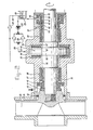
- a pump housing 34 accommodating therein a pump impeller 35 mounted on a shaft 36.
- this shaft is supported by means of two radial bearings 38 and 39 and an axial bearing 40.
- the radial bearing 38 conveys from the right to the left and receives its lubricating liquid from the chamber 58 by way of the axial bearing 40 and discharges the liquid by way of the elastomeric dirt arrestor 42 conveying in the same direction.
- the chamber 41 may be supplied with liquid through the opening 43 which liquid may be liquid from the surroundings such as water, or liquid supplied to the opening by means of a line and a pressure pump. This is the so called gland flushing water which in cooperation with the gland 60 will prevent abrasive material present in the suction pump from reaching the dirt arrestor.
- the radial bearing 39 conveys from the left to the right and discharges towards a chamber 44 provided with an elastomeric sleeve 45, which sleeve possesses a conveying groove 46 through which liquid leaks away in a controlled manner to the chamber 47 provided with a discharge 48 and a lip shaped elastomeric sleeve 50 cooperating with a smooth bush 49.
- Lubricating liquid such as clean water may be supplied, optionally under pressurized conditions to the chamber 58 by way of the channel 59. This may be performed in the same manner as described with reference to Fig. 1.
- an axial bearing 40 consisting of a disc 53 fixedly mounted on the shaft which disc 53 cooperates with elastomeric discs 54 and 55 fixedly mounted in the house 37 and having a smooth surface facing the disc 53.
- the disc 53 is provided with grooves running from the space 56 and 57, respectively, between the shaft and the house to the annular chamber 58 surrounding the axial bearing.
- These grooves have flanks which at least in the direction of rotation form a small angle of aperture with the face of the disc and which consequently in cooperation with the surfaces of the elastomeric discs 54 and 55 will form dynamically small lubricating wedges when loaded. These grooves will however also provide for conveyance of the liquid at the same time. This liquid flows from the chamber 58 to the spaces 56 and 57 and then through the bearings 36 and 39 and the dirt arrestor 42 and the metering seal 45, 46, respectively.
- the medium in the pump 34, 35 does not contain abrasive particles and this medium is suitable for lubrication, cooling and flushing of the bearing and the seal the supply of medium by means of an additional flushing pump by way of the inlet 43 as well as the dirt arrestor 42 and the gland 60 may be omitted.
- the medium of the pump will then serve the several functions and will be discharged in a controlled manner by way of the discharge 48.
- the supply at 59 may then be omitted.
- the grooves of the radial bearing 38 and those of the axial bearing cooperating with the disc 54 and 55 will then be designed such that the direction of conveyance is from the left to the right.
- a higher throughput may be achieved by utilizing additional channels 61 in the axial bearing.
Landscapes
- Engineering & Computer Science (AREA)
- General Engineering & Computer Science (AREA)
- Mechanical Engineering (AREA)
- Chemical & Material Sciences (AREA)
- Oil, Petroleum & Natural Gas (AREA)
- Sliding-Contact Bearings (AREA)
- Sealing Of Bearings (AREA)
- Sealing Using Fluids, Sealing Without Contact, And Removal Of Oil (AREA)
- Glass Compositions (AREA)
- Golf Clubs (AREA)
- Sealing With Elastic Sealing Lips (AREA)
- Sealing Devices (AREA)
Claims (8)
Priority Applications (1)
| Application Number | Priority Date | Filing Date | Title |
|---|---|---|---|
| AT81200428T ATE6882T1 (de) | 1980-04-18 | 1981-04-14 | Abgedichtetes lager. |
Applications Claiming Priority (2)
| Application Number | Priority Date | Filing Date | Title |
|---|---|---|---|
| NL8002280A NL8002280A (nl) | 1980-04-18 | 1980-04-18 | Lager met afdichting. |
| NL8002280 | 1980-04-18 |
Publications (2)
| Publication Number | Publication Date |
|---|---|
| EP0039114A1 EP0039114A1 (fr) | 1981-11-04 |
| EP0039114B1 true EP0039114B1 (fr) | 1984-03-28 |
Family
ID=19835171
Family Applications (1)
| Application Number | Title | Priority Date | Filing Date |
|---|---|---|---|
| EP81200428A Expired EP0039114B1 (fr) | 1980-04-18 | 1981-04-14 | Palier étanche |
Country Status (9)
| Country | Link |
|---|---|
| US (1) | US4381127A (fr) |
| EP (1) | EP0039114B1 (fr) |
| JP (2) | JPS56167918A (fr) |
| AT (1) | ATE6882T1 (fr) |
| BR (1) | BR8102361A (fr) |
| DE (1) | DE3162855D1 (fr) |
| ES (1) | ES266001Y (fr) |
| NL (1) | NL8002280A (fr) |
| SU (1) | SU1097210A3 (fr) |
Cited By (2)
| Publication number | Priority date | Publication date | Assignee | Title |
|---|---|---|---|---|
| RU2242647C2 (ru) * | 2002-12-10 | 2004-12-20 | Открытое акционерное общество "Силовые машины-ЗТЛ, ЛМЗ, Электросила, Энергомашэкспорт" | Устройство уплотнения подшипников скольжения с центральной системой смазки |
| DE102013215453A1 (de) * | 2013-08-06 | 2015-02-12 | Schaeffler Technologies Gmbh & Co. Kg | Tauchlageranordnung |
Families Citing this family (14)
| Publication number | Priority date | Publication date | Assignee | Title |
|---|---|---|---|---|
| DE3248097A1 (de) * | 1982-12-24 | 1984-06-28 | Karl Otto Technisches Büro für Verfahrenstechnologie, 3054 Rodenberg | Radialgleitlager, insbesondere fuer die welle einer wasserturbine |
| US4787332A (en) * | 1986-02-12 | 1988-11-29 | Robotics, Inc. | Adhesive dispensing pump control system |
| US4699575A (en) * | 1986-02-12 | 1987-10-13 | Robotics, Inc. | Adhesive pump and it's control system |
| FI860951A0 (fi) * | 1986-03-06 | 1986-03-06 | Waertsilae Oy Ab | Lagerarrangemang foer propelleraxel. |
| US4795273A (en) * | 1986-03-06 | 1989-01-03 | Oy Wartsila Ab | Propeller shaft bearing arrangement |
| GB2230305A (en) * | 1989-04-05 | 1990-10-17 | Vickers Plc | Thrust bearing. |
| US5735603A (en) * | 1996-05-03 | 1998-04-07 | Littleford Day, Inc. | Horizontal mixer apparatus and method with improved shaft and seal structure |
| US6471394B2 (en) | 2001-03-07 | 2002-10-29 | Littleford Day, Incorporated | Mixer apparatus and method with improved shaft stub end seal structure |
| EP2048385A1 (fr) * | 2007-10-11 | 2009-04-15 | Carl Freudenberg KG | Agencement de palier |
| US7562879B1 (en) * | 2008-04-30 | 2009-07-21 | Cnh America Llc | Method and apparatus for creating an auger arm and bearing seal |
| EP2932109A4 (fr) * | 2012-12-17 | 2016-05-25 | Ride The Ducks International Llc | Boîtier de palier |
| US11983498B2 (en) * | 2021-03-18 | 2024-05-14 | Augmented Intelligence Technologies, Inc. | System and methods for language processing of document sequences using a neural network |
| DE102022115057B4 (de) | 2022-06-15 | 2025-10-02 | Vibracoustic Se | Lagerbuchse |
| DE102022207817A1 (de) * | 2022-07-28 | 2024-02-08 | Zf Friedrichshafen Ag | Elektrische Achse mit einem Radnabenschmiersystem sowie Fahrzeug mit der elektrischen Achse |
Family Cites Families (18)
| Publication number | Priority date | Publication date | Assignee | Title |
|---|---|---|---|---|
| NL65303C (fr) * | ||||
| US1376043A (en) * | 1920-02-24 | 1921-04-26 | Sherwood Charles Frederic | Shaft-bearing |
| US1510804A (en) * | 1921-06-23 | 1924-10-07 | Charles F Sherwood | Shaft lining |
| US2663599A (en) * | 1950-05-18 | 1953-12-22 | Fairbanks Morse & Co | Line shaft guide bearing |
| US3150822A (en) * | 1961-02-09 | 1964-09-29 | Commissariat Energie Atomique | Sealing and centering device for rotary shaft |
| US3302988A (en) * | 1963-12-17 | 1967-02-07 | Plastic & Rubber Prod Co | Shaft bearing with removable bearing insert |
| NL6512869A (fr) * | 1965-10-05 | 1967-04-06 | ||
| FR1546372A (fr) | 1966-12-07 | 1968-11-15 | Philips Nv | Palier lisse hydrodynamique |
| NL6617168A (fr) * | 1966-12-07 | 1968-06-10 | ||
| FR1546285A (fr) * | 1966-12-07 | 1968-11-15 | Philips Nv | Palier lisse hydrodynamique |
| NL149575B (nl) * | 1966-12-07 | 1976-05-17 | Philips Nv | Legerbus voor een hydrodynamisch leger. |
| DE1775763A1 (de) * | 1968-09-20 | 1971-08-12 | Passera Walter Dipl Ing | Radialgleitlager |
| GB1188230A (en) * | 1968-11-13 | 1970-04-15 | Aconcagau Compania Panamena De | Improvements in Bearing Assemblies |
| DE2142031A1 (de) | 1971-08-21 | 1973-02-22 | Josef Dr Graw | Geraeuscharme, kaeltebestaendige selbstschmierende gleitlagerung |
| FR2288909A1 (fr) * | 1974-10-21 | 1976-05-21 | Activite Atom Avance | Joint tournant d'etancheite par effet visqueux |
| GB1510842A (en) * | 1975-07-08 | 1978-05-17 | Forsheda Ideutveckling Ab | Shaft sealing and bearing arrangement especially for propeller shafts |
| US3981547A (en) * | 1975-07-15 | 1976-09-21 | Perruzzi John E | Spiral, tapered-land, journal bearing |
| US4194745A (en) * | 1979-05-02 | 1980-03-25 | Mcdougal Thomas L | Controlled clearance seal |
-
1980
- 1980-04-18 NL NL8002280A patent/NL8002280A/nl not_active Application Discontinuation
-
1981
- 1981-04-14 AT AT81200428T patent/ATE6882T1/de active
- 1981-04-14 DE DE8181200428T patent/DE3162855D1/de not_active Expired
- 1981-04-14 EP EP81200428A patent/EP0039114B1/fr not_active Expired
- 1981-04-15 ES ES1981266001U patent/ES266001Y/es not_active Expired
- 1981-04-15 BR BR8102361A patent/BR8102361A/pt unknown
- 1981-04-16 US US06/254,984 patent/US4381127A/en not_active Expired - Fee Related
- 1981-04-18 SU SU813276093A patent/SU1097210A3/ru active
- 1981-04-18 JP JP5907281A patent/JPS56167918A/ja active Pending
-
1987
- 1987-02-16 JP JP1987021254U patent/JPS62151432U/ja active Pending
Cited By (3)
| Publication number | Priority date | Publication date | Assignee | Title |
|---|---|---|---|---|
| RU2242647C2 (ru) * | 2002-12-10 | 2004-12-20 | Открытое акционерное общество "Силовые машины-ЗТЛ, ЛМЗ, Электросила, Энергомашэкспорт" | Устройство уплотнения подшипников скольжения с центральной системой смазки |
| DE102013215453A1 (de) * | 2013-08-06 | 2015-02-12 | Schaeffler Technologies Gmbh & Co. Kg | Tauchlageranordnung |
| DE102013215453B4 (de) * | 2013-08-06 | 2015-08-27 | Schaeffler Technologies AG & Co. KG | Tauchlageranordnung |
Also Published As
| Publication number | Publication date |
|---|---|
| ATE6882T1 (de) | 1984-04-15 |
| NL8002280A (nl) | 1981-11-16 |
| BR8102361A (pt) | 1981-12-22 |
| JPS56167918A (en) | 1981-12-23 |
| ES266001U (es) | 1983-01-16 |
| JPS62151432U (fr) | 1987-09-25 |
| EP0039114A1 (fr) | 1981-11-04 |
| SU1097210A3 (ru) | 1984-06-07 |
| US4381127A (en) | 1983-04-26 |
| ES266001Y (es) | 1983-07-16 |
| DE3162855D1 (en) | 1984-05-03 |
Similar Documents
| Publication | Publication Date | Title |
|---|---|---|
| EP0039114B1 (fr) | Palier étanche | |
| US8505924B2 (en) | Rotary shaft sealing assembly | |
| EP0037210B1 (fr) | Combinaison d'étanchéité pompant en direction de la région de haute pression | |
| EP0769111B1 (fr) | Ensemble comprenant un joint d'etancheite et un palier de roulement | |
| US3484113A (en) | Mechanical seal with flushing arrangement | |
| US4613281A (en) | Hydrodynamic seal | |
| GB2290113A (en) | Centrifugal pump shaft seal cooling and venting | |
| US8790072B2 (en) | Bearing assembly for a vertical turbine pump | |
| RU2179653C2 (ru) | Уплотняющая система гидравлической машины | |
| US3292847A (en) | Lubricant sealing means for rotary positive displacement pump | |
| CA1299211C (fr) | Amelioration de la lubrification de garniture mecanique | |
| EP0086002A1 (fr) | Joint d'étanchéité pour l'arbre d'une pompe | |
| US4718820A (en) | Pumping apparatus | |
| EP0920592A1 (fr) | Systeme d'etancheite pour arbre de pompe | |
| WO1985000639A1 (fr) | Moyen d'etancheite pour une pompe a piston axial a haute pression | |
| US6004094A (en) | Radially sealed centrifugal pump | |
| JPS61123795A (ja) | 遠心ポンプ | |
| US4445695A (en) | Rotary mechanical seals | |
| US4648794A (en) | Pump with high speed expeller | |
| FR2468804A1 (fr) | Dispositif a plusieurs joints separes d'etancheite pour machine tournante | |
| US5368313A (en) | Bushing for trapped bushing seal | |
| EP0671321A1 (fr) | Joint d'étanchéité avec lubrification de graisse pour les tubes d'étambot | |
| US3490064A (en) | Bearing and mercury seal for the shafts in rotary devices such as pumps | |
| GB2094907A (en) | Rotary mechanical seal | |
| JP2821989B2 (ja) | 軸封装置 |
Legal Events
| Date | Code | Title | Description |
|---|---|---|---|
| PUAI | Public reference made under article 153(3) epc to a published international application that has entered the european phase |
Free format text: ORIGINAL CODE: 0009012 |
|
| AK | Designated contracting states |
Designated state(s): AT BE CH DE FR GB IT LU NL SE |
|
| 17P | Request for examination filed |
Effective date: 19811118 |
|
| ITF | It: translation for a ep patent filed | ||
| GRAA | (expected) grant |
Free format text: ORIGINAL CODE: 0009210 |
|
| AK | Designated contracting states |
Designated state(s): AT BE CH DE FR GB IT LI LU NL SE |
|
| REF | Corresponds to: |
Ref document number: 6882 Country of ref document: AT Date of ref document: 19840415 Kind code of ref document: T |
|
| PGFP | Annual fee paid to national office [announced via postgrant information from national office to epo] |
Ref country code: CH Payment date: 19840412 Year of fee payment: 4 |
|
| PGFP | Annual fee paid to national office [announced via postgrant information from national office to epo] |
Ref country code: DE Payment date: 19840419 Year of fee payment: 4 |
|
| PGFP | Annual fee paid to national office [announced via postgrant information from national office to epo] |
Ref country code: FR Payment date: 19840420 Year of fee payment: 4 |
|
| PG25 | Lapsed in a contracting state [announced via postgrant information from national office to epo] |
Ref country code: LU Free format text: LAPSE BECAUSE OF NON-PAYMENT OF DUE FEES Effective date: 19840430 |
|
| REF | Corresponds to: |
Ref document number: 3162855 Country of ref document: DE Date of ref document: 19840503 |
|
| PGFP | Annual fee paid to national office [announced via postgrant information from national office to epo] |
Ref country code: SE Payment date: 19840630 Year of fee payment: 4 Ref country code: BE Payment date: 19840630 Year of fee payment: 4 |
|
| ET | Fr: translation filed | ||
| PLBE | No opposition filed within time limit |
Free format text: ORIGINAL CODE: 0009261 |
|
| STAA | Information on the status of an ep patent application or granted ep patent |
Free format text: STATUS: NO OPPOSITION FILED WITHIN TIME LIMIT |
|
| 26N | No opposition filed | ||
| PGFP | Annual fee paid to national office [announced via postgrant information from national office to epo] |
Ref country code: AT Payment date: 19860421 Year of fee payment: 6 |
|
| PGFP | Annual fee paid to national office [announced via postgrant information from national office to epo] |
Ref country code: NL Payment date: 19860430 Year of fee payment: 6 |
|
| PG25 | Lapsed in a contracting state [announced via postgrant information from national office to epo] |
Ref country code: AT Effective date: 19870414 |
|
| PG25 | Lapsed in a contracting state [announced via postgrant information from national office to epo] |
Ref country code: SE Effective date: 19870415 |
|
| PG25 | Lapsed in a contracting state [announced via postgrant information from national office to epo] |
Ref country code: LI Effective date: 19870430 Ref country code: CH Effective date: 19870430 |
|
| BERE | Be: lapsed |
Owner name: IHC HOLLAND N.V. Effective date: 19870430 |
|
| PG25 | Lapsed in a contracting state [announced via postgrant information from national office to epo] |
Ref country code: NL Effective date: 19871101 |
|
| NLV4 | Nl: lapsed or anulled due to non-payment of the annual fee | ||
| PG25 | Lapsed in a contracting state [announced via postgrant information from national office to epo] |
Ref country code: FR Free format text: LAPSE BECAUSE OF NON-PAYMENT OF DUE FEES Effective date: 19871230 |
|
| GBPC | Gb: european patent ceased through non-payment of renewal fee | ||
| REG | Reference to a national code |
Ref country code: CH Ref legal event code: PL |
|
| PG25 | Lapsed in a contracting state [announced via postgrant information from national office to epo] |
Ref country code: DE Effective date: 19880101 |
|
| REG | Reference to a national code |
Ref country code: FR Ref legal event code: ST |
|
| PG25 | Lapsed in a contracting state [announced via postgrant information from national office to epo] |
Ref country code: GB Effective date: 19881118 |
|
| PG25 | Lapsed in a contracting state [announced via postgrant information from national office to epo] |
Ref country code: BE Effective date: 19890430 |
|
| EUG | Se: european patent has lapsed |
Ref document number: 81200428.1 Effective date: 19880906 |