EP0039208A2 - Verseilmaschine - Google Patents
Verseilmaschine Download PDFInfo
- Publication number
- EP0039208A2 EP0039208A2 EP81301794A EP81301794A EP0039208A2 EP 0039208 A2 EP0039208 A2 EP 0039208A2 EP 81301794 A EP81301794 A EP 81301794A EP 81301794 A EP81301794 A EP 81301794A EP 0039208 A2 EP0039208 A2 EP 0039208A2
- Authority
- EP
- European Patent Office
- Prior art keywords
- pintle
- rotor
- support
- bobbin
- pair
- Prior art date
- Legal status (The legal status is an assumption and is not a legal conclusion. Google has not performed a legal analysis and makes no representation as to the accuracy of the status listed.)
- Granted
Links
- 230000013011 mating Effects 0.000 claims 2
- 230000000694 effects Effects 0.000 description 3
- 238000004519 manufacturing process Methods 0.000 description 3
- 230000008901 benefit Effects 0.000 description 2
- 210000002445 nipple Anatomy 0.000 description 2
- 238000007789 sealing Methods 0.000 description 2
- 230000008859 change Effects 0.000 description 1
- 239000011248 coating agent Substances 0.000 description 1
- 238000000576 coating method Methods 0.000 description 1
- 230000000295 complement effect Effects 0.000 description 1
- 238000010276 construction Methods 0.000 description 1
- 230000008878 coupling Effects 0.000 description 1
- 238000010168 coupling process Methods 0.000 description 1
- 238000005859 coupling reaction Methods 0.000 description 1
- 238000006073 displacement reaction Methods 0.000 description 1
- 239000002783 friction material Substances 0.000 description 1
- 230000005484 gravity Effects 0.000 description 1
- 238000003780 insertion Methods 0.000 description 1
- 230000037431 insertion Effects 0.000 description 1
- 239000002184 metal Substances 0.000 description 1
- 238000000034 method Methods 0.000 description 1
- 230000008569 process Effects 0.000 description 1
- 230000004044 response Effects 0.000 description 1
Images

Classifications
-
- B—PERFORMING OPERATIONS; TRANSPORTING
- B65—CONVEYING; PACKING; STORING; HANDLING THIN OR FILAMENTARY MATERIAL
- B65H—HANDLING THIN OR FILAMENTARY MATERIAL, e.g. SHEETS, WEBS, CABLES
- B65H49/00—Unwinding or paying-out filamentary material; Supporting, storing or transporting packages from which filamentary material is to be withdrawn or paid-out
- B65H49/18—Methods or apparatus in which packages rotate
- B65H49/20—Package-supporting devices
- B65H49/26—Axial shafts or spigots
-
- D—TEXTILES; PAPER
- D07—ROPES; CABLES OTHER THAN ELECTRIC
- D07B—ROPES OR CABLES IN GENERAL
- D07B7/00—Details of, or auxiliary devices incorporated in, rope- or cable-making machines; Auxiliary apparatus associated with such machines
- D07B7/02—Machine details; Auxiliary devices
- D07B7/06—Bearing supports or brakes for supply bobbins or reels
Definitions
- a stranding machine of the kind referred to characterised in that at least one pintle support of each pair is stepwise displaceable in the direction of the pintle axis relative to the rotor beam between a finite number of predetermined, axially spaced position in each of which it can be selectively secured to the rotor beam.
- An important advantage of a machine embodying the present invention is that it can readily be adjusted to produce cables from thread bobbins of different nominal widths, simply by axially shifting one or both pintle supports of each pair correspondingly and securing the pintle support or supports to the rotor in the changed position.
- a cable manufacturer who in his present production employes bobbins of one width, but who plans to change the production, at some later date, to a different bobbin width (normally to wider bobbins) can now purchase a new stranding machine without being forced to simultaneously purchase a large number of new bobbins and -auxiliary equipment for "threading" those new bobbins.
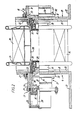
- the cable stranding machine illustrated in the drawings comprises a rotor, generally designated by 1, which at its ends is secured to two tubular shafts 2 and 3, through which the rotor is rotatably supported--in two bearing brackets 4.
- the rotor is driven by an electric motor 5 mounted on the bearing bracket 4 at the rotor inlet end and coupled to shaft 2 by means of a belt 6.
- a disc brake 7 for braking the rotor there is provided a disc brake 7, the brake disc 8 of which is secured to shaft 2.
- Rotor 1 is composed of two parallel longitudinal beams 9 and 10 of channel section with parallel webs 11 and outwardly protruding flanges 12, and transversely extending bracing walls 14 having flanges 15 through which the walls are bolted to the opposed webs of the longitudinal beams. At their ends beams 9 and 10 are bolted to outwardly extending flanges on shafts 2 and 3.
- bobbin bearing devices 16 and 17 are secured to the webs 11 of the longitudinal beams.
- One bobbin bearing device .16 of each pair consists of a stationary pintle support or bearing stud 18 and a pintle 19 rotatably supported on the end of the stud 18 inwardly of web 11.
- the other bobbin bearing-device 17 has a corresponding pintle 19 rotatably supported on the inner end of an axially displaceable pintle support or bearing stud 20.
- the outer or rear end of stud 20 is hollow and constitutes a pneumatic cylinder having two working chambers 21 and 22 located on opposite sides of a piston 23 in sealing contact with the cylinder wall.
- the outward end of the cylinder is closed by a cover 24 and by means of a central bolt 25 extending in sealing contact through cover 24 piston 23 is secured to a disc 26 rigidly connected to a housing 27 which is secured to the web 11 of longitudinal beam 9 in the same manner as bearing stud 18 is secured to the opposed longitudinal beam.
- a-thread layer on bobbin 29 has been indicated at 30.
- each of the pintles 19 shown at the left-hand side of Fig. 2 is retracted in response to the supply-of pressurized air to the working chamber 22 through a central bore in bolt 25 while working chamber 21 is vented to the atmosphere. Since piston 23 is axially immovable, the hollow bearing stud 20 and the pintle 19 are thereby retracted. After insertion of the bobbins the connections to chambers 21 and 22 are reversed, whereby stud 20 and pintle 19 are pushed into bobbin shaft 28. Normally, the bearing studs 20 are maintained in the working position shown in Fig. 2 by the air pressure within chamber 21, but as a further safety device in case the pressure should fail, there is provided a manually releasable ball detent 31 which in its active position, as shown, prevents axial displacement of stud 20 relative to housing 27.
- a clamping ring 32 which is bolted to the respective web 11 by a plurality of bolts 47, and a profiled locking ring 33 which engages in a circumferential groove 34 in the surface of stud 18 or housing 20, as the case may be, and is clamped between web 11 and ring 32 which, as shown may be formed with complementary profiles.
- Locking rings 33 which have been shown with a hexagonal cross-section may be split so that they are expandable for being pushed into their positions in grooves 34, but each locking ring could also be made as two half-rings,
- Fig. 2 there are provided three axially offset grooves 34 in each of components 18 and 27. This permits mounting of each bearing device in three different axial positions whereby the machine can be adjusted, in an extremely simple manner, to accommodate bobbins of correspondingly different nominal width.
- bobbins 29 While only four bobbins 29 have been shown in Fig. 1, the rotor will normally comprise six pairs of opposed bobbin bearing devices 16 and 17.
- a thread 35 is unwound from each bobbin, and each thread 35 except that unwound from the bobbin next to the rotor outlet is tracked across a guide bar 36 of low-friction material which is secured across longitudinal beams 9 and 10 in the region of the adjacent transverse wall 14. From guide bar 36 the thread continues freely to a guide roller 37 rotatably supported by a transverse wall 39 extending between rotor beams 9,10 and forming the inner end of shaft 3.
- threads 35 are tracked through apertures in an end flange 40 of the rotor and further through inclined guide bushes in shaft 3 to a stranding or closing nipple (not shown) located outside the rotor outlet.
- a stranding or closing nipple (not shown) located outside the rotor outlet.
- the six threads are twisted together about a core thread 41 which from a thread bobbin (not shown) is introduced into the rotor through hollow shaft 2 as shown in Fig. 1.
- the apertures defined between longitudinal beams 9 and 10 and transverse walls 14, and through which the rotor is loaded and unloaded, are closed by means of two sheet metal covers 42, each of which is hinged to a respective longitudinal beam for permitting access to the bobbin bearing devices during loading and unloading of the machine.
- a guard 45 shown schematically in Fig. 1 and which can be swung away to permit access to the rotor.
- On the inner surface of guard 45 there may be provided a sound absorbing coating.
- the machine For braking bobbins 29 during operation of the machine in order to maintain a suitable thread tension, the machine is, in a known manner, provided with a pneumatic bobbin brake on each bobbin bearing device 16.
- this brake has been indicated by way of its brake disc 46 secured to one pintle 19.
- Pressurized air for actuating the bobbin brakes can, in a known manner, be supplied from a receptacle located outside the rotor through a rotary air coupling (not shown) in connection with tubular shaft 2.
- the invention has been described above in connection with a strander having a single row of thread bobbins, the axes of which intersect the rotor axis. With similar advantages the invention can also be utilized in rigid cage stranders in which two or more rows of bobbins are distributed along the rotor periphery.
Landscapes
- Ropes Or Cables (AREA)
- Insulated Conductors (AREA)
- Processes Specially Adapted For Manufacturing Cables (AREA)
- Gas-Insulated Switchgears (AREA)
Priority Applications (1)
| Application Number | Priority Date | Filing Date | Title |
|---|---|---|---|
| AT81301794T ATE8416T1 (de) | 1980-04-30 | 1981-04-23 | Verseilmaschine. |
Applications Claiming Priority (2)
| Application Number | Priority Date | Filing Date | Title |
|---|---|---|---|
| DK1916/80 | 1980-04-30 | ||
| DK191680 | 1980-04-30 |
Publications (3)
| Publication Number | Publication Date |
|---|---|
| EP0039208A2 true EP0039208A2 (de) | 1981-11-04 |
| EP0039208A3 EP0039208A3 (en) | 1982-01-27 |
| EP0039208B1 EP0039208B1 (de) | 1984-07-11 |
Family
ID=8108964
Family Applications (1)
| Application Number | Title | Priority Date | Filing Date |
|---|---|---|---|
| EP81301794A Expired EP0039208B1 (de) | 1980-04-30 | 1981-04-23 | Verseilmaschine |
Country Status (6)
| Country | Link |
|---|---|
| US (1) | US4369619A (de) |
| EP (1) | EP0039208B1 (de) |
| AT (1) | ATE8416T1 (de) |
| CA (1) | CA1153642A (de) |
| DE (1) | DE3164685D1 (de) |
| ES (1) | ES501758A0 (de) |
Families Citing this family (2)
| Publication number | Priority date | Publication date | Assignee | Title |
|---|---|---|---|---|
| US4506499A (en) * | 1984-01-03 | 1985-03-26 | The Watson Machine Company | Reel support system |
| US8635848B2 (en) | 2011-01-21 | 2014-01-28 | Afl Telecommunications Llc | Method and apparatus for preventing stranding elements from crossing during a stranding process |
Family Cites Families (15)
| Publication number | Priority date | Publication date | Assignee | Title |
|---|---|---|---|---|
| GB196605A (en) * | 1922-04-19 | 1924-04-03 | Soennecken F | Improved mounting for the paper rolls of machines for copying documents and the like |
| NL17159C (de) * | 1924-02-19 | |||
| US2270093A (en) * | 1941-01-23 | 1942-01-13 | Charles F Van Hook | Retracting pintle cradle for stranding and/or closing machines |
| US2452255A (en) * | 1946-11-29 | 1948-10-26 | Mckosky Michael | Spool adapter for rope layers or stranding machines |
| US2690642A (en) * | 1948-11-20 | 1954-10-05 | Charles F Van Hook | Twisting machine |
| US2787884A (en) * | 1953-05-22 | 1957-04-09 | Syncro Mach Co | Cable stranding machine |
| US2860479A (en) * | 1953-12-16 | 1958-11-18 | Aluminum Co Of America | Reel supporting cradles |
| DE956214C (de) * | 1955-06-14 | 1957-01-17 | Achenbach Soehne Ges Mit Besch | Einrichtung zum axialen Einstellen eines Wickelbundes bei einer Wickelvorrichtung fuer bandartiges Gut, insbesondere fuer Baender aus Metall |
| US2959907A (en) * | 1958-02-24 | 1960-11-15 | Synchro Machine Company | Cradle assembly for stranding machine |
| US2972854A (en) * | 1958-04-02 | 1961-02-28 | Syncro Mach Co | Cradle assembly for stranding machine |
| US2903842A (en) * | 1958-06-02 | 1959-09-15 | Syncro Mach Co | Cradle assembly for stranding machine |
| GB1208293A (en) * | 1966-10-27 | 1970-10-14 | Filament Extruders Pty Ltd | The forming of spiralled or twisted synthetic plastic fibres |
| DE2165563A1 (de) | 1971-12-30 | 1973-07-05 | Krupp Gmbh | Verseilmaschine |
| DD100509A1 (de) * | 1972-11-17 | 1973-09-20 | ||
| US4079580A (en) * | 1977-03-07 | 1978-03-21 | Ceeco Machinery Manufacturing Limited | Fail-safe locking device for reel carrying systems |
-
1981
- 1981-04-23 AT AT81301794T patent/ATE8416T1/de not_active IP Right Cessation
- 1981-04-23 EP EP81301794A patent/EP0039208B1/de not_active Expired
- 1981-04-23 DE DE8181301794T patent/DE3164685D1/de not_active Expired
- 1981-04-27 US US06/258,012 patent/US4369619A/en not_active Expired - Fee Related
- 1981-04-27 CA CA000376327A patent/CA1153642A/en not_active Expired
- 1981-04-29 ES ES501758A patent/ES501758A0/es active Granted
Also Published As
| Publication number | Publication date |
|---|---|
| EP0039208A3 (en) | 1982-01-27 |
| US4369619A (en) | 1983-01-25 |
| ES8300908A1 (es) | 1982-11-01 |
| CA1153642A (en) | 1983-09-13 |
| DE3164685D1 (en) | 1984-08-16 |
| EP0039208B1 (de) | 1984-07-11 |
| ATE8416T1 (de) | 1984-07-15 |
| ES501758A0 (es) | 1982-11-01 |
Similar Documents
| Publication | Publication Date | Title |
|---|---|---|
| US6021974A (en) | Winding arrangement for coiling of an elongated flexible element and coiling means | |
| US5277690A (en) | Roll | |
| US4369619A (en) | Cable stranding machine | |
| DE2508896C3 (de) | Verfahren zum Verseilen mehrerer Adern zu einem elektrischen Kabel | |
| FI109195B (fi) | Paperi- ja kartonkiratojen rullaaja | |
| US4450676A (en) | Apparatus for stranding optical fiber cores while slackening them | |
| CA1173705A (en) | Apparatus for stranding wire | |
| US4850086A (en) | Warper with ironing rolls | |
| US5367352A (en) | Direction-changing roller for suspension frames of photographic material developing machines | |
| FI91681C (fi) | Laitteisto optisen kuitukimpun kiinnittämiseksi kaapelirungon uriin menetelmä kuitujen ylipituuden säätämiseksi urissa | |
| EP2421781B1 (de) | System umfassend einen drehantrieb und eine wickelgutspule zur aufnahme von lade- und verseilgut | |
| WO2002068834A1 (de) | Walze zum führen von zumindest einem faden | |
| DE2519691C2 (de) | Verseilmaschine | |
| US2899921A (en) | Ffjtth | |
| EP2310306B1 (de) | Verfahren zum aufwickeln einer laufenden materialbahn sowie wickelmaschine zur durchführung des verfahrens | |
| US4469286A (en) | Free floating rider roll beam mounting | |
| EP0096833A2 (de) | Fadenspeicher | |
| DE102019110138B4 (de) | Wickelstation und Verfahren zum Aufwickeln einer Mehrzahl von Metallstreifen zu einer Mehrzahl von Bandrollen | |
| US4434608A (en) | Method and an apparatus for manufacturing strands from wires or ropes from strands | |
| WO2006059862A9 (en) | Automatic loading and supplying apparatus for roll matter | |
| FI79505B (fi) | Upprullningsanordning. | |
| EP1584739B1 (de) | Rohrförmige Verseilmaschine | |
| US5407056A (en) | Apparatus and method for distributively feeding plural winding bobbins | |
| SU772503A3 (ru) | Крутильна машина дл пучковой скрутки токопровод щих жил | |
| DE2163020C3 (de) | Anordnung von mehreren Aufwickelvorrichtungen an Spulmaschinen |
Legal Events
| Date | Code | Title | Description |
|---|---|---|---|
| PUAI | Public reference made under article 153(3) epc to a published international application that has entered the european phase |
Free format text: ORIGINAL CODE: 0009012 |
|
| AK | Designated contracting states |
Designated state(s): AT CH DE FR GB IT |
|
| PUAL | Search report despatched |
Free format text: ORIGINAL CODE: 0009013 |
|
| AK | Designated contracting states |
Designated state(s): AT CH DE FR GB IT |
|
| 17P | Request for examination filed |
Effective date: 19820315 |
|
| ITF | It: translation for a ep patent filed | ||
| GRAA | (expected) grant |
Free format text: ORIGINAL CODE: 0009210 |
|
| AK | Designated contracting states |
Designated state(s): AT CH DE FR GB IT LI |
|
| REF | Corresponds to: |
Ref document number: 8416 Country of ref document: AT Date of ref document: 19840715 Kind code of ref document: T |
|
| REF | Corresponds to: |
Ref document number: 3164685 Country of ref document: DE Date of ref document: 19840816 |
|
| ET | Fr: translation filed | ||
| PLBE | No opposition filed within time limit |
Free format text: ORIGINAL CODE: 0009261 |
|
| STAA | Information on the status of an ep patent application or granted ep patent |
Free format text: STATUS: NO OPPOSITION FILED WITHIN TIME LIMIT |
|
| 26N | No opposition filed | ||
| REG | Reference to a national code |
Ref country code: CH Ref legal event code: PUE Owner name: OY NOKIA AB |
|
| REG | Reference to a national code |
Ref country code: GB Ref legal event code: 732 |
|
| PGFP | Annual fee paid to national office [announced via postgrant information from national office to epo] |
Ref country code: AT Payment date: 19860415 Year of fee payment: 6 |
|
| REG | Reference to a national code |
Ref country code: FR Ref legal event code: TP |
|
| ITPR | It: changes in ownership of a european patent |
Owner name: CESSIONE;OY NOKIA AB |
|
| PG25 | Lapsed in a contracting state [announced via postgrant information from national office to epo] |
Ref country code: AT Effective date: 19870423 |
|
| PG25 | Lapsed in a contracting state [announced via postgrant information from national office to epo] |
Ref country code: LI Effective date: 19870430 Ref country code: CH Effective date: 19870430 |
|
| PG25 | Lapsed in a contracting state [announced via postgrant information from national office to epo] |
Ref country code: FR Free format text: LAPSE BECAUSE OF NON-PAYMENT OF DUE FEES Effective date: 19871230 |
|
| GBPC | Gb: european patent ceased through non-payment of renewal fee | ||
| REG | Reference to a national code |
Ref country code: CH Ref legal event code: PL |
|
| PG25 | Lapsed in a contracting state [announced via postgrant information from national office to epo] |
Ref country code: DE Effective date: 19880101 |
|
| REG | Reference to a national code |
Ref country code: FR Ref legal event code: ST |
|
| PG25 | Lapsed in a contracting state [announced via postgrant information from national office to epo] |
Ref country code: GB Effective date: 19881118 |