EP0039236A1 - Brennstoffzellen-Kühlung mit variabler Fläche - Google Patents
Brennstoffzellen-Kühlung mit variabler Fläche Download PDFInfo
- Publication number
- EP0039236A1 EP0039236A1 EP81301866A EP81301866A EP0039236A1 EP 0039236 A1 EP0039236 A1 EP 0039236A1 EP 81301866 A EP81301866 A EP 81301866A EP 81301866 A EP81301866 A EP 81301866A EP 0039236 A1 EP0039236 A1 EP 0039236A1
- Authority
- EP
- European Patent Office
- Prior art keywords
- cooling
- passages
- fuel cell
- surface area
- inlet
- Prior art date
- Legal status (The legal status is an assumption and is not a legal conclusion. Google has not performed a legal analysis and makes no representation as to the accuracy of the status listed.)
- Granted
Links
Images


Classifications
-
- F—MECHANICAL ENGINEERING; LIGHTING; HEATING; WEAPONS; BLASTING
- F28—HEAT EXCHANGE IN GENERAL
- F28F—DETAILS OF HEAT-EXCHANGE AND HEAT-TRANSFER APPARATUS, OF GENERAL APPLICATION
- F28F13/00—Arrangements for modifying heat-transfer, e.g. increasing, decreasing
- F28F13/06—Arrangements for modifying heat-transfer, e.g. increasing, decreasing by affecting the pattern of flow of the heat-exchange media
- F28F13/08—Arrangements for modifying heat-transfer, e.g. increasing, decreasing by affecting the pattern of flow of the heat-exchange media by varying the cross-section of the flow channels
-
- H—ELECTRICITY
- H01—ELECTRIC ELEMENTS
- H01M—PROCESSES OR MEANS, e.g. BATTERIES, FOR THE DIRECT CONVERSION OF CHEMICAL ENERGY INTO ELECTRICAL ENERGY
- H01M8/00—Fuel cells; Manufacture thereof
- H01M8/02—Details
- H01M8/0202—Collectors; Separators, e.g. bipolar separators; Interconnectors
- H01M8/0258—Collectors; Separators, e.g. bipolar separators; Interconnectors characterised by the configuration of channels, e.g. by the flow field of the reactant or coolant
-
- H—ELECTRICITY
- H01—ELECTRIC ELEMENTS
- H01M—PROCESSES OR MEANS, e.g. BATTERIES, FOR THE DIRECT CONVERSION OF CHEMICAL ENERGY INTO ELECTRICAL ENERGY
- H01M8/00—Fuel cells; Manufacture thereof
- H01M8/02—Details
- H01M8/0202—Collectors; Separators, e.g. bipolar separators; Interconnectors
- H01M8/0258—Collectors; Separators, e.g. bipolar separators; Interconnectors characterised by the configuration of channels, e.g. by the flow field of the reactant or coolant
- H01M8/026—Collectors; Separators, e.g. bipolar separators; Interconnectors characterised by the configuration of channels, e.g. by the flow field of the reactant or coolant characterised by grooves, e.g. their pitch or depth
-
- H—ELECTRICITY
- H01—ELECTRIC ELEMENTS
- H01M—PROCESSES OR MEANS, e.g. BATTERIES, FOR THE DIRECT CONVERSION OF CHEMICAL ENERGY INTO ELECTRICAL ENERGY
- H01M8/00—Fuel cells; Manufacture thereof
- H01M8/02—Details
- H01M8/0202—Collectors; Separators, e.g. bipolar separators; Interconnectors
- H01M8/0258—Collectors; Separators, e.g. bipolar separators; Interconnectors characterised by the configuration of channels, e.g. by the flow field of the reactant or coolant
- H01M8/0265—Collectors; Separators, e.g. bipolar separators; Interconnectors characterised by the configuration of channels, e.g. by the flow field of the reactant or coolant the reactant or coolant channels having varying cross sections
-
- H—ELECTRICITY
- H01—ELECTRIC ELEMENTS
- H01M—PROCESSES OR MEANS, e.g. BATTERIES, FOR THE DIRECT CONVERSION OF CHEMICAL ENERGY INTO ELECTRICAL ENERGY
- H01M8/00—Fuel cells; Manufacture thereof
- H01M8/02—Details
- H01M8/0202—Collectors; Separators, e.g. bipolar separators; Interconnectors
- H01M8/0267—Collectors; Separators, e.g. bipolar separators; Interconnectors having heating or cooling means, e.g. heaters or coolant flow channels
-
- H—ELECTRICITY
- H01—ELECTRIC ELEMENTS
- H01M—PROCESSES OR MEANS, e.g. BATTERIES, FOR THE DIRECT CONVERSION OF CHEMICAL ENERGY INTO ELECTRICAL ENERGY
- H01M8/00—Fuel cells; Manufacture thereof
- H01M8/04—Auxiliary arrangements, e.g. for control of pressure or for circulation of fluids
- H01M8/04007—Auxiliary arrangements, e.g. for control of pressure or for circulation of fluids related to heat exchange
- H01M8/04014—Heat exchange using gaseous fluids; Heat exchange by combustion of reactants
-
- H—ELECTRICITY
- H01—ELECTRIC ELEMENTS
- H01M—PROCESSES OR MEANS, e.g. BATTERIES, FOR THE DIRECT CONVERSION OF CHEMICAL ENERGY INTO ELECTRICAL ENERGY
- H01M8/00—Fuel cells; Manufacture thereof
- H01M8/24—Grouping of fuel cells, e.g. stacking of fuel cells
- H01M8/2465—Details of groupings of fuel cells
-
- H—ELECTRICITY
- H01—ELECTRIC ELEMENTS
- H01M—PROCESSES OR MEANS, e.g. BATTERIES, FOR THE DIRECT CONVERSION OF CHEMICAL ENERGY INTO ELECTRICAL ENERGY
- H01M8/00—Fuel cells; Manufacture thereof
- H01M8/24—Grouping of fuel cells, e.g. stacking of fuel cells
- H01M8/2465—Details of groupings of fuel cells
- H01M8/2484—Details of groupings of fuel cells characterised by external manifolds
-
- Y—GENERAL TAGGING OF NEW TECHNOLOGICAL DEVELOPMENTS; GENERAL TAGGING OF CROSS-SECTIONAL TECHNOLOGIES SPANNING OVER SEVERAL SECTIONS OF THE IPC; TECHNICAL SUBJECTS COVERED BY FORMER USPC CROSS-REFERENCE ART COLLECTIONS [XRACs] AND DIGESTS
- Y02—TECHNOLOGIES OR APPLICATIONS FOR MITIGATION OR ADAPTATION AGAINST CLIMATE CHANGE
- Y02E—REDUCTION OF GREENHOUSE GAS [GHG] EMISSIONS, RELATED TO ENERGY GENERATION, TRANSMISSION OR DISTRIBUTION
- Y02E60/00—Enabling technologies; Technologies with a potential or indirect contribution to GHG emissions mitigation
- Y02E60/30—Hydrogen technology
- Y02E60/50—Fuel cells
Definitions
- This invention relates to improved cooling arrangements for fuel cell systems.
- fuel cell systems include subassemblies of two bipolar plates between which is supported an electrolyte, such as an acid, in a matrix.
- the subassemblies herein referred to as fuel cells, are oriented one atop another and electrically connected in series to form a fuel cell stack.
- Operation of the fuel cell for example the reaction of hydrogen and oxygen to produce electrical energy as well as water and heat, is exothermic, and cooling of the cell components is necessary in order to maintain component integrity.
- the bipolar plates or the electrolyte matrix may be made of carbonaceous material bonded by a resin which tends to degrade at high temperatures. Prolonged operation at high temperatures would tend to degrade many components of a typical fuel cell.
- the exothermic reaction can result in uneven temperature distribution across a fuel cell, thus limiting cell- operating temperature and efficiency, and additionally raising concerns about catalyst poisoning, for example, by carbon monoxide.
- fuel cell systems have in the past been proposed with closed liquid cooling loops.
- systems comprising a plurality of stacked cells where every fourth cell or so includes small metallic tubing through which cooling water is recirculated. Circulatory power is accordingly required, detracting from overall cell efficiency. This is complicated by large pressure drops in small diameter tubing, and the susceptibility of the cooling tubes to attack by mediums within the cell stack, such as acids in certain designs.
- the cooling module passages are much larger than the fuel cell process channels so that approximately eighty percent of the air flows through the cooling cell passages and the balance through the process cell channels. While such systems represent an improvement in terms of mechanical power requirements, additional improvements can be made. For example, where the amount of airflow is reasonable, that is, where an amount which does not require excess circulatory power is utilized, the air flowing through the cooling channels absorbs substantial amounts of heat energy as the cooling passsage is traversed, resulting in less cooling at the exit end of the channel. This condition results in an uneven temperature profile in the fuel cell stack and attendant unbalanced reaction rates, voltage and current distributions, and limits maximum operating temperatures.
- the invention resides in a cooling arrangement for a fuel cell system wherein two process fuel cells connected electrically are separated by a cooling module and a fluid oxidant is fed in parallel through process channels in said fuel cells and through at least one cooling passage in said cooling module, said at least one cooling passage having an inlet and an outlet, characterized in that said at least one cooling passage is of a variable surface area which generally increases from said inlet to said outlet.
- This invention provides a cooling arrangement for stacked fuel cell systems which alleviates unbalanced temperature distributions and does not require excessively high cooling fluid flow rates.
- a plurality of fuel cells are provided in a stack, and a cooling module is periodically positioned between two selected fuel cells.
- Process channels within the fuel cells are arranged to transfer an oxidant, such as air, through the cells in a direction preferably generally parallel to the flow of air through the passages of the cooling modules.
- the cooling passages are substantially larger than the fuel cell process channels.
- the process channels are of generally constant cross section throughout their length, or can include a variable cross section.
- the cooling passages are provided with a surface area that varies in a predetermined fashion from inlet to outlet. More specifically, the cooling passages are provided with a smaller cross-sectional and/or larger surface areas at the outlets.
- the cooling passage inlets are preferably arranged so that the inlets are along the side of the cell stack exposed to fresh oxidant, and the outlets are along the side of the cell stack exposed to depleted oxidant.
- the surface area of the cooling cell passages progressively increases from inlet to outlet. In this manner, as the cooling air traverses the cell passages absorbing heat energy and correspondingly lowering its cooling ability, it also contacts a larger surface area, correspondingly increasing its cooling ability. The net result is more evenly distributed cooling resulting in more uniform cell temperatures.
- the lateral distance among adjacent channels can also be advantageously varied to more closely match uneven reaction distribtuion which tends to be higher at the process fuel inlet end of the cell and lower at the process fuel outlet end of the cell.
- the surface area of the cooling passages can be varied, including branching the passages from a singular inlet to a plurality of preferably smaller outlets.
- the passage shape can also be modified, for example, from rectangular to cruciform. Substantially rectangular-based channel shapes are preferred in order to most advantageously match cooling requirements with distribution of heat generation.
- an electrochemical fuel cell system 10 The system includes a plurality of repeating fuel cells 12 arranged in a stack such that the cells 12 are electrically connected in series. Cell stacks can also be arranged in parallel.
- An individual cell such as the cell 12', includes two bipolar plates 14 between which are sandwiched an electrolyte, for example, in the form of a porous graphite matrix 16 saturated with an acid such as phosphoric acid.
- the plates 14 can comprise a material such as compression molded graphite-resin composite, disposed on opposite sides of the electrolyte matrix 16 and electrodes 18, such as the cathode 20 and anode 22.
- Each electrode 18 can also be of a porous graphite material provided with a porous graphite fiber backing 24 for added structural integrity.
- the bipolar plates 14 are provided with a set of process channels, including fuel channels 26 and oxidant channels 28.
- the channels 26, 28 are generally rectangular with slightly slanted edges 30 to facilitate fabrication as necessary, for example, to remove a fabrication die.
- the bipolar plates 14 also include grooves 32 mat- ingly configured to receive the electrodes 18. Thus, when held together by means well known, such as bonding materials and an external frame, each cell represents a substantially sealed unit.
- An oxidant such as a halogen, or air or other oxygen-containing material, flows through the oxidant channels 28, and a fuel, such as hydrogen, organics or metals, flows through the fuel channels 26.
- Manifolds 27 are typically utilized to, for example, provide oxidant to the oxidant inlet side 34 of the cell system stack and to receive the oxidant from the oxidant outlet side 36 of the stack. Similarly, manifolds are provided on the fuel inlet side 38 and fuel outlet side 40. Electrical power and heat are generated by the interaction of the fuel and oxidant through the electrodes and electrolyte matrix 16.
- An exemplary fuel cell 13 utilizes hydrogen fuel, air as the oxidant and phosphoric acid as the electrolyte.
- the system stack 10 includes cooling modules 42.
- the cooling modules 42 are placed between fuel cells 12 at selected positions within the stack 10.
- a cooling module 42 may, for example, be placed between approximately every third cell to every eighth cell.
- Each cooling module 42 is preferably comprised of a material similar to that of the bipolar plates 14, compression molded graphite-resin composite in the exemplary system.
- the cooling module 42 includes a plurality of passages 44, described more fully hereinafter.
- the cooling module 42 can be formed of one piece, although, as shown, two sections 46 are preferably separately fabricated and subsequently sealed together.
- the cooling passages 44 are preferably substantially rectangular, although other geometric shapes are equally possible. Where the cooling module is formed in two sections 46, cooling passage edges 48 are preferably slanted slightly, as are the fuel cell channels 28, approximately seven degrees from vertical, to accommodate removal of a die during fabrication.
- the cooling passages 44 are preferably oriented generally parallel to the oxidant channels 28, although they can also be oriented parallel to the fuel channels 26. The latter, however, requires more complex manifolding.
- a cooling fluid flows through the cooling passages 44.
- the cooling fluid and oxidant are the same medium, such as air.
- air is brought from a singular manifold 27 to the oxidant inlet side 34 of the fuel cell system stack 10, and flows in parallel and in the same direction through the cooling passages 44 and oxidant process channels 28.
- the surface area of the cooling passages 44 is varied with the distance from the inlet end of the passages. A small surface area is provided at the inlet end and a larger surface area is provided at the exit end.
- the increase in surface area can be provided in a number of manners, such as by changing the geometry or perimeter of a given passage as a function of distance, or by dividing the passsages into additional branches along the direction of flow.
- the variation can either be continuous or can include step changes.
- the actual passage shape may be dictated by fabrication preference.
- a cooling passage 44 includes a first segment having a singular branch 44', a second segment including two branches 44", and a third segment including three branches 44''', respectively, from inlet toward outlet. Each segment is approximately one-third of the length of the entire passage.
- the rectangular shape shown is preferred since it is relatively simple to fabricate and match with desired cooling requirements.
- the surface area defined by the branches 44', 44'', 44''', progressively increases.
- Figs. 6 through 8 represent a series of segments, respectively, from inlet to outlet, where the geometry is modified to provide an increasing surface area.
- a similar sequence is shown in Figs. 9 through 12.
- Figs. 13 and 14 show a passage 44, rectangular in cross section, which gradually increases in surface area from inlet to outlet
- Figs. 15 and 16 show a passage 44, circular in cross section, which gradually increases from inlet to outlet.
- Many additional configurations are equally possible.
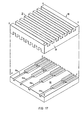
- adjacent passages can also be spaced laterally in a predetermined manner. Particularly, as shown in Fig. 17, cooling passages 44a and 44b are spaced closer together than, for example, passages 44c and 44d. As fuel traverses the channels 26 from inlet 38 to outlet 40, the fuel is gradually depleted. Accordingly, the heat generated by the exothermic reaction is greater at the fuel inlet 38 and less toward the fuel outlet 40. By spacing the cooling passages 44 so that more cooling air flows adjacent the fuel inlet and less cooling air flows at the fuel outlet, a more even temperature distribution across the cell is achieved.
- the bipolar plates can be at constant temperature, T , by setting
- This ratio is readily achieved by dividing a larger channel at the inlet into two or three channels at the exit, particularly as an intensity of cooling factor ratio of 4:1 does not require a 4:1 surface area ratio, since h will increase due to a smaller channel hydraulic diameter at the outlet.
- cooling passage shapes are possible, and that hydraulic diameter is an important factor when selecting passage shape and surface area.
- Preferred shapes are those which reduce hydraulic diameter and simultaneously increase surface area so as to provide an increase in both the cooling area and the heat transfer coefficient, the intensity of cooling per unit area.
- the cooling airflow which produces a 75°F rise would result in approximately a 75°F temperature variation among adjacent bipolar plates where cooling channel surface area variation, as disclosed, is not utilized. This temperature variation is reduced to approximately 25°F with the disclosed surface area variation.
- the advantages resulting from a more even temperature distribution are substantial, including the allowance of higher average bipolar plate temperature for a given maximum temperature.
- the disclosed system not only reduces the airflow required and accordingly the required circulator power, but further alleviates the effects of carbon monoxide catalyst poisoning which decreases with increasing operating temperature and, accordingly, is lessened by the higher average temperature.
Landscapes
- Engineering & Computer Science (AREA)
- Chemical & Material Sciences (AREA)
- Sustainable Development (AREA)
- General Chemical & Material Sciences (AREA)
- Electrochemistry (AREA)
- Chemical Kinetics & Catalysis (AREA)
- Sustainable Energy (AREA)
- Life Sciences & Earth Sciences (AREA)
- Manufacturing & Machinery (AREA)
- Mechanical Engineering (AREA)
- Combustion & Propulsion (AREA)
- General Engineering & Computer Science (AREA)
- Physics & Mathematics (AREA)
- Thermal Sciences (AREA)
- Fuel Cell (AREA)
Applications Claiming Priority (2)
| Application Number | Priority Date | Filing Date | Title |
|---|---|---|---|
| US06/144,090 US4324844A (en) | 1980-04-28 | 1980-04-28 | Variable area fuel cell cooling |
| US144090 | 1980-04-28 |
Publications (2)
| Publication Number | Publication Date |
|---|---|
| EP0039236A1 true EP0039236A1 (de) | 1981-11-04 |
| EP0039236B1 EP0039236B1 (de) | 1985-05-15 |
Family
ID=22506996
Family Applications (1)
| Application Number | Title | Priority Date | Filing Date |
|---|---|---|---|
| EP81301866A Expired EP0039236B1 (de) | 1980-04-28 | 1981-04-28 | Brennstoffzellen-Kühlung mit variabler Fläche |
Country Status (6)
| Country | Link |
|---|---|
| US (1) | US4324844A (de) |
| EP (1) | EP0039236B1 (de) |
| JP (1) | JPS57852A (de) |
| BR (1) | BR8102275A (de) |
| DE (1) | DE3170475D1 (de) |
| ZA (1) | ZA812049B (de) |
Cited By (9)
| Publication number | Priority date | Publication date | Assignee | Title |
|---|---|---|---|---|
| EP0098495A1 (de) * | 1982-06-28 | 1984-01-18 | Energy Research Corporation | Brennstoffzellensystem |
| FR2918798A1 (fr) * | 2007-07-10 | 2009-01-16 | Air Liquide | Plaque de pile a combustible, empilage de cellules de pile a combustible et pile a combustible comprenant une telle plaque. |
| GB2464274A (en) * | 2008-10-07 | 2010-04-14 | Intelligent Energy Ltd | Fuel Cell Assembly |
| CN101197452B (zh) * | 2006-11-22 | 2010-06-02 | 通用汽车环球科技运作公司 | 对带有金属板的燃料电池的补充的冷却剂加热 |
| WO2011065906A3 (en) * | 2009-11-24 | 2011-07-28 | Air To Air Sweden Ab | A method of producing multiple channels for use in a device for exchange of solutes or heat between fluid flows |
| GB2524733A (en) * | 2014-03-31 | 2015-10-07 | Intelligent Energy Ltd | Cooling plates for fuel cells |
| US9683789B2 (en) | 2009-11-24 | 2017-06-20 | Air To Air Sweden Ab | Method of producing multiple channels for use in a device for exchange of solutes or heat between fluid flows |
| DE102023122870A1 (de) | 2023-08-25 | 2024-06-20 | Schaeffler Technologies AG & Co. KG | Kühlmodul eines elektrochemischen Systems, Zellenstapel und Verfahren zur Herstellung eines Kühlmoduls |
| GB2628145A (en) * | 2023-03-15 | 2024-09-18 | Zeroavia Ltd | Bidirectional (staggered) bipolar plate pattern for fuel cell cooling |
Families Citing this family (77)
| Publication number | Priority date | Publication date | Assignee | Title |
|---|---|---|---|---|
| DE3119409A1 (de) * | 1981-05-15 | 1982-12-09 | Brown, Boveri & Cie Ag, 6800 Mannheim | "hochtemperaturbatterie" |
| US4416955A (en) * | 1982-01-11 | 1983-11-22 | Energy Research Corporation | Fuel cell sub-assembly |
| US4508793A (en) * | 1982-09-08 | 1985-04-02 | Sanyo Electric Co., Ltd. | Air-cooled fuel cell system |
| CA1229376A (en) * | 1983-06-02 | 1987-11-17 | John Werth | Fuel cell crimp-resistant cooling device with internal support |
| US4945010A (en) * | 1983-06-02 | 1990-07-31 | Engelhard Corporation | Cooling assembly for fuel cells |
| US4476197A (en) * | 1983-10-12 | 1984-10-09 | The United States Of America As Represented By The United States Department Of Energy | Integral manifolding structure for fuel cell core having parallel gas flow |
| US4476196A (en) * | 1983-10-12 | 1984-10-09 | The United States Of America As Represented By The United States Department Of Energy | Solid oxide fuel cell having monolithic cross flow core and manifolding |
| US4476198A (en) * | 1983-10-12 | 1984-10-09 | The United States Of America As Represented By The United States Department Of Energy | Solid oxide fuel cell having monolithic core |
| US4510212A (en) * | 1983-10-12 | 1985-04-09 | The United States Of America As Represented By The United States Department Of Energy | Solid oxide fuel cell having compound cross flow gas patterns |
| US4664988A (en) * | 1984-04-06 | 1987-05-12 | Kureha Kagaku Kogyo Kabushiki Kaisha | Fuel cell electrode substrate incorporating separator as an intercooler and process for preparation thereof |
| JPS6130968U (ja) * | 1984-07-28 | 1986-02-25 | 株式会社 富士電機総合研究所 | 燃料電池セルスタツク |
| US4572876A (en) * | 1985-04-01 | 1986-02-25 | Westinghouse Electric Corp. | Apparatus for supplying electrolyte to fuel cell stacks |
| FR2582156B1 (fr) * | 1985-05-15 | 1988-03-04 | Thomson Csf | Oscillateur hyperfrequences fonctionnant en bande millimetrique |
| JPS6273568A (ja) * | 1985-09-26 | 1987-04-04 | Toshiba Corp | 燃料電池 |
| US4853301A (en) * | 1985-12-04 | 1989-08-01 | The United States Of America As Represented By The United States Department Of Energy | Fuel cell plates with skewed process channels for uniform distribution of stack compression load |
| US4631239A (en) * | 1985-12-04 | 1986-12-23 | Westinghouse Electric Corp. | Fuel cell plates with improved arrangement of process channels for enhanced pressure drop across the plates |
| US4732822A (en) * | 1986-12-10 | 1988-03-22 | The United States Of America As Represented By The United States Department Of Energy | Internal electrolyte supply system for reliable transport throughout fuel cell stacks |
| US5108849A (en) * | 1989-08-30 | 1992-04-28 | Her Majesty The Queen In Right Of Canada, As Represented By The Minister Of National Defence In Her Britannic Majesty's Government Of The United Kingdom Of Great Britain And Northern Ireland | Fuel cell fluid flow field plate |
| US4988583A (en) * | 1989-08-30 | 1991-01-29 | Her Majesty The Queen As Represented By The Minister Of National Defence Of Her Majesty's Canadian Government | Novel fuel cell fluid flow field plate |
| US5547776A (en) * | 1991-01-15 | 1996-08-20 | Ballard Power Systems Inc. | Electrochemical fuel cell stack with concurrently flowing coolant and oxidant streams |
| US5541015A (en) * | 1992-05-12 | 1996-07-30 | Sanyo Electric Co., Ltd. | Fuel cell using a separate gas cooling method |
| JP2551713B2 (ja) * | 1992-07-15 | 1996-11-06 | 株式会社日立製作所 | 燃料電池 |
| US5773160A (en) * | 1994-06-24 | 1998-06-30 | Ballard Power Systems Inc. | Electrochemical fuel cell stack with concurrent flow of coolant and oxidant streams and countercurrent flow of fuel and oxidant streams |
| JP4037448B2 (ja) * | 1995-05-25 | 2008-01-23 | 本田技研工業株式会社 | 燃料電池 |
| JP3604848B2 (ja) | 1996-01-18 | 2004-12-22 | 日本碍子株式会社 | 電気化学セル用積層焼結体、電気化学セルおよび電気化学セル用積層焼結体の製造方法 |
| JPH11317236A (ja) | 1997-12-22 | 1999-11-16 | Aqueous Reserch:Kk | 燃料電池システム |
| JP4543440B2 (ja) * | 1997-12-22 | 2010-09-15 | 株式会社エクォス・リサーチ | 水直噴型燃料電池システム |
| US7029775B2 (en) * | 1997-12-22 | 2006-04-18 | Kabushikikaisha Equos Research | Fuel cell system |
| GB9814120D0 (en) * | 1998-07-01 | 1998-08-26 | British Gas Plc | Cooling of fuel cell stacks |
| WO2000036680A1 (en) * | 1998-12-17 | 2000-06-22 | International Fuel Cells, Llc | A cooling plate for a fuel cell stack assembly |
| JP4686814B2 (ja) | 1999-11-17 | 2011-05-25 | 株式会社エクォス・リサーチ | 燃料電池装置 |
| DE10007763B4 (de) * | 2000-02-20 | 2017-04-06 | General Motors Corp. (N.D.Ges.D. Staates Delaware) | Brennstoffzellenanordnung |
| EP1265303B1 (de) * | 2000-03-07 | 2009-07-01 | Panasonic Corporation | Polymer-elektroly-brennstoffzelle und herstellungsverfahren dafür |
| JP2003529195A (ja) * | 2000-03-28 | 2003-09-30 | マンハッタン・サイエンティフィックス・インコーポレイテッド | 燃料電池装置とその動作方法 |
| JP2001332288A (ja) * | 2000-05-24 | 2001-11-30 | Honda Motor Co Ltd | 燃料電池スタック |
| JP4516229B2 (ja) * | 2001-03-06 | 2010-08-04 | 本田技研工業株式会社 | 固体高分子型セルアセンブリ |
| US20030035984A1 (en) | 2001-08-15 | 2003-02-20 | Colborn Jeffrey A. | Metal fuel cell system for providing backup power to one or more loads |
| US6780536B2 (en) * | 2001-09-17 | 2004-08-24 | 3M Innovative Properties Company | Flow field |
| US6783884B2 (en) | 2002-04-12 | 2004-08-31 | Ballard Power Systems Inc. | Flow field plate assembly for an electrochemical fuel cell |
| JP4308515B2 (ja) | 2002-12-27 | 2009-08-05 | パナソニック株式会社 | 電池モジュール |
| US7482088B2 (en) * | 2003-01-31 | 2009-01-27 | 3M Innovative Properties Company | Flow field |
| CA2547141C (en) * | 2003-11-28 | 2009-06-30 | Toyota Jidosha Kabushiki Kaisha | Fuel cell having coolant channel for cooling the fuel cell |
| FR2865028B1 (fr) * | 2004-01-12 | 2006-12-29 | Ziepack | Echangeur thermique et module d'echange s'y rapportant |
| EP1624515B1 (de) * | 2004-05-28 | 2008-12-17 | Du Pont Canada Inc. | Einstückige Brennstoffzellen-Untereinheit und Methode zu deren Herstellung |
| ITMI20041314A1 (it) * | 2004-06-30 | 2004-09-30 | Nuvera Fuel Cells Europ Srl | Dispositivo di raffreddamento per celle a combustibili a membrana |
| KR100637504B1 (ko) * | 2004-08-30 | 2006-10-20 | 삼성에스디아이 주식회사 | 연료 전지 시스템 및 그 스택 |
| US7041408B1 (en) * | 2004-12-28 | 2006-05-09 | Utc Fuel Cells, Llc | Varied fuel cell oxidant flow channel depth resulting in fewer cooler plates |
| WO2006071233A1 (en) * | 2004-12-29 | 2006-07-06 | Utc Power Corporation | Fuel cell assembly with operating temperatures for extended life |
| EP1848051A4 (de) * | 2005-01-04 | 2009-09-02 | Nec Corp | Hülle für eine filmgepackte elektrische einrichtung und filmgepackte elektrische einrichtungsbaugruppe |
| US7361427B1 (en) | 2005-05-27 | 2008-04-22 | The United States Of America Represented By The Secretary Of The Navy | Manifold for a pile configured battery |
| EP1736715A1 (de) * | 2005-06-23 | 2006-12-27 | Sgl Carbon Ag | Vakuumröhren für Solarkollektoren mit verbessertem Wärmeübergang |
| US7833645B2 (en) * | 2005-11-21 | 2010-11-16 | Relion, Inc. | Proton exchange membrane fuel cell and method of forming a fuel cell |
| JP5021219B2 (ja) * | 2006-03-01 | 2012-09-05 | 本田技研工業株式会社 | 燃料電池スタック |
| US7985505B2 (en) * | 2006-12-15 | 2011-07-26 | General Electric Company | Fuel cell apparatus and associated method |
| US20080145723A1 (en) * | 2006-12-15 | 2008-06-19 | General Electric Company | Rechargeable fuel cell and method |
| US8343687B2 (en) * | 2006-12-19 | 2013-01-01 | General Electric Company | Rechargeable fuel cell system |
| FR2913819A1 (fr) * | 2007-03-16 | 2008-09-19 | Air Liquide | Plaque de pile a combustible, empilage de cellules de pile a combustible et pile a combustible correspondante |
| US8026020B2 (en) | 2007-05-08 | 2011-09-27 | Relion, Inc. | Proton exchange membrane fuel cell stack and fuel cell stack module |
| DE102007024161A1 (de) * | 2007-05-24 | 2008-11-27 | Daimler Ag | Bipolarplatte für Brennstoffzellen |
| US9293778B2 (en) | 2007-06-11 | 2016-03-22 | Emergent Power Inc. | Proton exchange membrane fuel cell |
| US8003274B2 (en) | 2007-10-25 | 2011-08-23 | Relion, Inc. | Direct liquid fuel cell |
| JP5365162B2 (ja) * | 2008-11-26 | 2013-12-11 | 日産自動車株式会社 | 燃料電池 |
| US8168344B2 (en) * | 2009-02-20 | 2012-05-01 | Clearedge Power, Inc. | Air-cooled thermal management for a fuel cell stack |
| KR101126203B1 (ko) * | 2009-12-15 | 2012-03-22 | 삼성에스디아이 주식회사 | 연료 전지 스택 및 이를 구비한 연료 전지 시스템 |
| CA2840020C (en) | 2011-07-05 | 2018-07-17 | Toyota Jidosha Kabushiki Kaisha | Fuel cell including a separator having concave and convex shapes |
| US9644277B2 (en) | 2012-08-14 | 2017-05-09 | Loop Energy Inc. | Reactant flow channels for electrolyzer applications |
| CN104718651B (zh) | 2012-08-14 | 2017-07-28 | 环能源公司 | 燃料电池流动沟道和流场 |
| WO2014026287A1 (en) | 2012-08-14 | 2014-02-20 | Powerdisc Development Corporation Ltd. | Fuel cell components, stacks and modular fuel cell systems |
| KR101491372B1 (ko) * | 2013-12-17 | 2015-02-06 | 현대자동차주식회사 | 연료 전지 분리판 및 이를 포함하는 연료 전지 스택 |
| DE102014002829A1 (de) * | 2014-02-27 | 2015-08-27 | Wieland-Werke Ag | Metallisches Wärmeaustauscherrohr |
| CA3016102C (en) | 2016-03-22 | 2024-09-17 | Loop Energy Inc. | FUEL CELL FLOW FIELD DESIGN FOR THERMAL MANAGEMENT |
| JP6772200B2 (ja) * | 2018-01-09 | 2020-10-21 | 本田技研工業株式会社 | 発電セル |
| EP3543376A1 (de) | 2018-03-22 | 2019-09-25 | Hymeth ApS | Kühlplattenanordnung und elektrolysestapel damit |
| DE102021100186A1 (de) | 2021-01-08 | 2022-07-14 | Audi Aktiengesellschaft | Bipolarplatte mit im aktiven Bereich vorhandenen Kanalaufteilungen und Brennstoffzellenstapel |
| US12586798B2 (en) | 2021-07-03 | 2026-03-24 | Cevizdere LLC | Methods and apparatus for mold mitigation in fuel cell humidifiers |
| CN116608047B (zh) * | 2023-05-19 | 2025-11-18 | 长春理工大学 | 一种金枪鱼鳃丝仿生结构微通道预冷器 |
| CN116678651B (zh) * | 2023-05-19 | 2025-12-16 | 长春理工大学 | 一种金枪鱼鳃丝仿生结构微通道换热试验装置及方法 |
Citations (1)
| Publication number | Priority date | Publication date | Assignee | Title |
|---|---|---|---|---|
| US3709736A (en) * | 1970-08-17 | 1973-01-09 | Engelhard Min & Chem | Fuel cell system comprising noncirculating,counter-current gas flow means |
Family Cites Families (11)
| Publication number | Priority date | Publication date | Assignee | Title |
|---|---|---|---|---|
| US3160528A (en) * | 1961-11-30 | 1964-12-08 | Exxon Research Engineering Co | Portable power plant |
| US3432357A (en) * | 1964-09-28 | 1969-03-11 | Gen Electric | Fluent material distribution system and fuel cell therewith |
| GB1151373A (en) * | 1965-05-18 | 1969-05-07 | Energy Conversion Ltd | Improvements in and relating to Electrochemical Cell Arrangements |
| FR2259447B1 (de) * | 1974-01-25 | 1976-11-26 | Alsthom Cgee | |
| US4074020A (en) * | 1975-02-06 | 1978-02-14 | Societe Generale De Constructions Electriques Et Mecaniques "Alsthom Et Cie" | Cross-feed fuel cell battery with filter press type structure of polygonal cross-section |
| FR2304183A1 (fr) * | 1975-03-11 | 1976-10-08 | Accumulateurs Fixes | Pile a depolarisation par l'air |
| SE390582B (sv) * | 1975-05-12 | 1976-12-27 | Lindstroem Ab Olle | Anordning vid elektrokemiska batterier innehallande minst tva seriekopplade moduler med elektrolytrum som star i forbindelse med varandra |
| JPS52122844A (en) * | 1976-04-09 | 1977-10-15 | Hitachi Ltd | Stacked structure battery |
| US4129685A (en) * | 1977-08-15 | 1978-12-12 | United Technologies Corp. | Fuel cell structure |
| US4182795A (en) * | 1978-07-10 | 1980-01-08 | Energy Research Corporation | Fuel cell thermal control and reforming of process gas hydrocarbons |
| US4169917A (en) * | 1978-07-10 | 1979-10-02 | Energy Research Corporation | Electrochemical cell and separator plate thereof |
-
1980
- 1980-04-28 US US06/144,090 patent/US4324844A/en not_active Expired - Lifetime
-
1981
- 1981-03-26 ZA ZA00812049A patent/ZA812049B/xx unknown
- 1981-04-14 BR BR8102275A patent/BR8102275A/pt unknown
- 1981-04-28 DE DE8181301866T patent/DE3170475D1/de not_active Expired
- 1981-04-28 EP EP81301866A patent/EP0039236B1/de not_active Expired
- 1981-04-28 JP JP6350681A patent/JPS57852A/ja active Granted
Patent Citations (1)
| Publication number | Priority date | Publication date | Assignee | Title |
|---|---|---|---|---|
| US3709736A (en) * | 1970-08-17 | 1973-01-09 | Engelhard Min & Chem | Fuel cell system comprising noncirculating,counter-current gas flow means |
Cited By (12)
| Publication number | Priority date | Publication date | Assignee | Title |
|---|---|---|---|---|
| EP0098495A1 (de) * | 1982-06-28 | 1984-01-18 | Energy Research Corporation | Brennstoffzellensystem |
| CN101197452B (zh) * | 2006-11-22 | 2010-06-02 | 通用汽车环球科技运作公司 | 对带有金属板的燃料电池的补充的冷却剂加热 |
| FR2918798A1 (fr) * | 2007-07-10 | 2009-01-16 | Air Liquide | Plaque de pile a combustible, empilage de cellules de pile a combustible et pile a combustible comprenant une telle plaque. |
| GB2464274A (en) * | 2008-10-07 | 2010-04-14 | Intelligent Energy Ltd | Fuel Cell Assembly |
| WO2011065906A3 (en) * | 2009-11-24 | 2011-07-28 | Air To Air Sweden Ab | A method of producing multiple channels for use in a device for exchange of solutes or heat between fluid flows |
| AU2010325220B2 (en) * | 2009-11-24 | 2014-06-19 | Air To Air Sweden Ab | A method of producing multiple channels for use in a device for exchange of solutes or heat between fluid flows |
| RU2555103C2 (ru) * | 2009-11-24 | 2015-07-10 | Эйр Ту Эйр Свиден Аб | Способ изготовления множества каналов для использования в устройстве теплообмена между потоками текучей среды |
| US9683789B2 (en) | 2009-11-24 | 2017-06-20 | Air To Air Sweden Ab | Method of producing multiple channels for use in a device for exchange of solutes or heat between fluid flows |
| GB2524733A (en) * | 2014-03-31 | 2015-10-07 | Intelligent Energy Ltd | Cooling plates for fuel cells |
| US10038203B2 (en) | 2014-03-31 | 2018-07-31 | Intelligent Energy Limited | Cooling plates for fuel cells |
| GB2628145A (en) * | 2023-03-15 | 2024-09-18 | Zeroavia Ltd | Bidirectional (staggered) bipolar plate pattern for fuel cell cooling |
| DE102023122870A1 (de) | 2023-08-25 | 2024-06-20 | Schaeffler Technologies AG & Co. KG | Kühlmodul eines elektrochemischen Systems, Zellenstapel und Verfahren zur Herstellung eines Kühlmoduls |
Also Published As
| Publication number | Publication date |
|---|---|
| JPH0253909B2 (de) | 1990-11-20 |
| ZA812049B (en) | 1982-06-30 |
| US4324844A (en) | 1982-04-13 |
| JPS57852A (en) | 1982-01-05 |
| BR8102275A (pt) | 1982-01-12 |
| DE3170475D1 (en) | 1985-06-20 |
| EP0039236B1 (de) | 1985-05-15 |
Similar Documents
| Publication | Publication Date | Title |
|---|---|---|
| EP0039236B1 (de) | Brennstoffzellen-Kühlung mit variabler Fläche | |
| EP0039237B1 (de) | Brennstoffzellen-Prozesskanäle mit variabler Fläche | |
| US4582765A (en) | Fuel cell system with coolant flow reversal | |
| US5686199A (en) | Flow field plate for use in a proton exchange membrane fuel cell | |
| US5108849A (en) | Fuel cell fluid flow field plate | |
| US4988583A (en) | Novel fuel cell fluid flow field plate | |
| US4169917A (en) | Electrochemical cell and separator plate thereof | |
| JP3713912B2 (ja) | 燃料電池のガス通路板 | |
| CA2428816C (en) | Separator unit and fuel cell with separator unit | |
| EP0063199B1 (de) | Anordnungen von Brennstoffzellenstapeln | |
| EP0039235A1 (de) | Polygonales Brennstoffzellensystem | |
| US3902916A (en) | Rechargeable electrochemical generator | |
| JP2000231929A (ja) | 燃料電池 | |
| CN101944618A (zh) | 一种树状结构流场的质子交换膜燃料电池双极板 | |
| US6852442B2 (en) | Internal fuel staging for improved fuel cell performance | |
| US20040265675A1 (en) | Fuel Cell Flow Field Design | |
| WO2014167306A2 (en) | Fuel cells | |
| JP2570771B2 (ja) | 燃料電池の冷却方法 | |
| JP4601893B2 (ja) | 燃料電池のセパレータ | |
| CN118352585A (zh) | 一种液流电池结构及液流电池堆 | |
| CN214477553U (zh) | 一种燃料电池双极板 | |
| CN100464449C (zh) | 一种可使燃料电池堆在低压或常压下运行的导流极板 | |
| JPS6217959A (ja) | 溶融炭酸塩型燃料電池 | |
| EP0109727B1 (de) | Elektrochemische Vorrichtung | |
| CN222775333U (zh) | 质子交换膜燃料电池双极板起伏型组合流道及双极板 |
Legal Events
| Date | Code | Title | Description |
|---|---|---|---|
| PUAI | Public reference made under article 153(3) epc to a published international application that has entered the european phase |
Free format text: ORIGINAL CODE: 0009012 |
|
| AK | Designated contracting states |
Designated state(s): DE FR IT NL SE |
|
| 17P | Request for examination filed |
Effective date: 19820504 |
|
| ITF | It: translation for a ep patent filed | ||
| GRAA | (expected) grant |
Free format text: ORIGINAL CODE: 0009210 |
|
| AK | Designated contracting states |
Designated state(s): DE FR IT NL SE |
|
| REF | Corresponds to: |
Ref document number: 3170475 Country of ref document: DE Date of ref document: 19850620 |
|
| ET | Fr: translation filed | ||
| PLBE | No opposition filed within time limit |
Free format text: ORIGINAL CODE: 0009261 |
|
| STAA | Information on the status of an ep patent application or granted ep patent |
Free format text: STATUS: NO OPPOSITION FILED WITHIN TIME LIMIT |
|
| 26N | No opposition filed | ||
| ITTA | It: last paid annual fee | ||
| PGFP | Annual fee paid to national office [announced via postgrant information from national office to epo] |
Ref country code: NL Payment date: 19910430 Year of fee payment: 11 |
|
| PG25 | Lapsed in a contracting state [announced via postgrant information from national office to epo] |
Ref country code: NL Effective date: 19921101 |
|
| NLV4 | Nl: lapsed or anulled due to non-payment of the annual fee | ||
| ITPR | It: changes in ownership of a european patent |
Owner name: CESSIONE;ENVIRONMENTAL ENERGY SYSTEMS INC. |
|
| REG | Reference to a national code |
Ref country code: FR Ref legal event code: TP |
|
| ITPR | It: changes in ownership of a european patent |
Owner name: CAMBIO RAGIONE SOCIALE;FUEL CELL CORPORATION OF AM |
|
| EAL | Se: european patent in force in sweden |
Ref document number: 81301866.0 |
|
| PGFP | Annual fee paid to national office [announced via postgrant information from national office to epo] |
Ref country code: FR Payment date: 19980320 Year of fee payment: 18 |
|
| PGFP | Annual fee paid to national office [announced via postgrant information from national office to epo] |
Ref country code: SE Payment date: 19980323 Year of fee payment: 18 |
|
| PGFP | Annual fee paid to national office [announced via postgrant information from national office to epo] |
Ref country code: DE Payment date: 19980630 Year of fee payment: 18 |
|
| PG25 | Lapsed in a contracting state [announced via postgrant information from national office to epo] |
Ref country code: SE Free format text: LAPSE BECAUSE OF NON-PAYMENT OF DUE FEES Effective date: 19990429 |
|
| PG25 | Lapsed in a contracting state [announced via postgrant information from national office to epo] |
Ref country code: FR Free format text: LAPSE BECAUSE OF NON-PAYMENT OF DUE FEES Effective date: 19991231 |
|
| EUG | Se: european patent has lapsed |
Ref document number: 81301866.0 |
|
| REG | Reference to a national code |
Ref country code: FR Ref legal event code: ST |
|
| PG25 | Lapsed in a contracting state [announced via postgrant information from national office to epo] |
Ref country code: DE Free format text: LAPSE BECAUSE OF NON-PAYMENT OF DUE FEES Effective date: 20000201 |