EP0039390A2 - Trocknungs- und Reinigungsvorrichtung für einen Kältekreislauf - Google Patents
Trocknungs- und Reinigungsvorrichtung für einen Kältekreislauf Download PDFInfo
- Publication number
- EP0039390A2 EP0039390A2 EP81101234A EP81101234A EP0039390A2 EP 0039390 A2 EP0039390 A2 EP 0039390A2 EP 81101234 A EP81101234 A EP 81101234A EP 81101234 A EP81101234 A EP 81101234A EP 0039390 A2 EP0039390 A2 EP 0039390A2
- Authority
- EP
- European Patent Office
- Prior art keywords
- capillary
- filter
- conduit
- refrigerant circuit
- service
- Prior art date
- Legal status (The legal status is an assumption and is not a legal conclusion. Google has not performed a legal analysis and makes no representation as to the accuracy of the status listed.)
- Granted
Links
Images
Classifications
-
- F—MECHANICAL ENGINEERING; LIGHTING; HEATING; WEAPONS; BLASTING
- F25—REFRIGERATION OR COOLING; COMBINED HEATING AND REFRIGERATION SYSTEMS; HEAT PUMP SYSTEMS; MANUFACTURE OR STORAGE OF ICE; LIQUEFACTION SOLIDIFICATION OF GASES
- F25B—REFRIGERATION MACHINES, PLANTS OR SYSTEMS; COMBINED HEATING AND REFRIGERATION SYSTEMS; HEAT PUMP SYSTEMS
- F25B43/00—Arrangements for separating or purifying gases or liquids; Arrangements for vaporising the residuum of liquid refrigerant, e.g. by heat
- F25B43/003—Filters
-
- F—MECHANICAL ENGINEERING; LIGHTING; HEATING; WEAPONS; BLASTING
- F25—REFRIGERATION OR COOLING; COMBINED HEATING AND REFRIGERATION SYSTEMS; HEAT PUMP SYSTEMS; MANUFACTURE OR STORAGE OF ICE; LIQUEFACTION SOLIDIFICATION OF GASES
- F25B—REFRIGERATION MACHINES, PLANTS OR SYSTEMS; COMBINED HEATING AND REFRIGERATION SYSTEMS; HEAT PUMP SYSTEMS
- F25B41/00—Fluid-circulation arrangements
- F25B41/30—Expansion means; Dispositions thereof
- F25B41/37—Capillary tubes
Definitions
- the present invention relates to a dehydration filter for use in domestic refrigerators employing an evacuation system in the high pressure part.
- the invention concerns a dehydration filter to be inserted in the refrigerant circuit between the condenser and the capillary tube of the evaporator and connected to the service conduit employed for creating a vacuum within the refrigerant circuit prior to introducing thereinto the refrigerant fluid.
- the dehumidifying filters of the above defined kind and the associated inlet and/or outlet conduits are usually made of copper, it being generally known that considerable difficulties are encountered in connecting the filter with the respective conduits by brazing. These brazed or soldered connections are relatively fragile and expensive due to the employ of noble metal brazing alloys, and have to be made under suitable conditions in order to avoid refrigerant losses due to imperfect, porous and/or irregular seams.
- the main object of the present invention is therefore the provision of a filter which is connected to the respective refrigerant circuit by a reduced number of soldered connections and presents maximum safety, structural simplicity, ruggedness and reliable sealing function.
- this object is attained by a filtering and dehydrating unit adapted to be inserted in a refrigerant circuit between the condenser and the capillary tube of the evaporator thereof, and connected to a service vacuum conduit, said filter unit being characterized by the fact that the capillary is intimately associated with the service vacuum conduit, and that the connection of the capillary and the service conduit to the body of the filter unit is established by a single solder joint.
- connection between the end of the capillary tube and the service conduit is established by partially compressing the latter to form a seat for the end of the capillary, so as to facilitate the insertion of the two conduits together into the respective port of the filter unit and to reduce the section to be filled with the solder material.
- the end of the capillary is partially inserted into an opening formed in the service conduit, the latter being formed as an extension of the filter body.
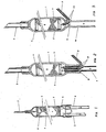
- the cylindrical body 1 of a known filter has one of its ends formed with a port for connection to a capillary 2, while its other end portion is laterally compressed to form two tubular ports for receiving therein a condensed conduit 3 and a vacuum service conduit 4, respectively.
- the gaseous refrigerant after having been compressed and subsequently cooled in condenser conduit 3, flows through the filter in the liquid state, the main function of said filter being to retain any humidity so as to avoid the formation of ice in capillary 2 with consequent blocking of the flow within the refrigerant circuit.
- the filter body 1 contains an absorbent material 7 such as silica gel or the like acting as a chemical filter, and mechanical filters 5, 6 disposed adjacent the inlet and the outlet of body 1, respectively, for retaining any solid contaminants and for preventing absorbent material 7 from being carried out of filter body 1 by the refrigerant fluid.
- an absorbent material 7 such as silica gel or the like acting as a chemical filter
- mechanical filters 5, 6 disposed adjacent the inlet and the outlet of body 1, respectively, for retaining any solid contaminants and for preventing absorbent material 7 from being carried out of filter body 1 by the refrigerant fluid.
- the refrigerant After passing through the filter, the refrigerant enters capillary 2 which funstions to control the amount of the fluid flowing towards the evaporator, wherein it develops its refrigerating effect due to evaporation and expansion in the gaseous phase.
- the air aspirated through service conduit 4 may enter thereinto directly from condenser conduit 3 without passing through filter body 1, thus avoiding any contamination or moistening of absorbent material 7.
- Fig. 2 shows a first embodiment of the filter unit according to the invention adapted to achieve the advantages described above.
- the filter unit shown comprises a tubular body 1 having two outwardly procecting hemispherical end portions for connection to an end portion of a condenser conduit 3 and the end portions of a service conduit 4 and a capillary 2, respectively.
- connection is preferably formed by locating the end portion of capillary 2 in a seat 8 formed in vacuum service conduit 4 by partially compressing its end portion. In this manner it is possible to connect both conduits together to the fikter body with minimum consumption of solder material by a single solder joint 12, so as to achieve maximum safety and reliability of the connection.
- Diagrammatically shown in fig. 3 is a second embodiment of the invention further simplified with respect to the one shown in fig. 2 and comprising a cylindrical filter body 1 having two end portions for connection to condenser conduit 3 and the combination of service conduit als capillary, respectively.
- the service tube 10 is formed as an integral extension of cylindrical body 1, the end portion of capillary 2 being inserted in to a port 11 formed in service conduit 10 and affixed thereto by a single solder joint 13.
- the refrigerant circuit functions in the well-known classical manner, i.e. the liquid refrigerant provenient from the condenser flows through the absorbent material 7 contained within filter body 1, and enters capillary 2 on its way towards the evaporator.
- the above described construction results in a difference, however, with regard to the flow path of the air aspirated from the circuit during evacuation thereof.
- the aspirated air passes through the absorbent filter material, in contrast to what happens in the case of prior art constructions. This feature could be disadvantageous, if the air originally contained in the circuit containes a certain degree of humidity sufficient to partially saturate the filter material.
- the filter unit according to the invention may obviously be modified in various manners.
- the diameters and wall thicknesses of the filter body and the various conduits as well as the materials employed may be selected in accordance with the characteristics of the refrigerant circuit.
Landscapes
- Engineering & Computer Science (AREA)
- Thermal Sciences (AREA)
- Analytical Chemistry (AREA)
- Power Engineering (AREA)
- Physics & Mathematics (AREA)
- Mechanical Engineering (AREA)
- Chemical & Material Sciences (AREA)
- General Engineering & Computer Science (AREA)
- Centrifugal Separators (AREA)
- Separation Using Semi-Permeable Membranes (AREA)
- Sink And Installation For Waste Water (AREA)
- Windings For Motors And Generators (AREA)
- Drying Of Solid Materials (AREA)
Priority Applications (1)
| Application Number | Priority Date | Filing Date | Title |
|---|---|---|---|
| AT81101234T ATE6173T1 (de) | 1980-05-05 | 1981-02-20 | Trocknungs- und reinigungsvorrichtung fuer einen kaeltekreislauf. |
Applications Claiming Priority (2)
| Application Number | Priority Date | Filing Date | Title |
|---|---|---|---|
| IT45717/80A IT1136391B (it) | 1980-05-05 | 1980-05-05 | Unita' deidratante e filtrante per un circuito frigorigeno |
| IT4571780 | 1980-05-05 |
Publications (3)
| Publication Number | Publication Date |
|---|---|
| EP0039390A2 true EP0039390A2 (de) | 1981-11-11 |
| EP0039390A3 EP0039390A3 (en) | 1982-04-28 |
| EP0039390B1 EP0039390B1 (de) | 1984-02-08 |
Family
ID=11257617
Family Applications (1)
| Application Number | Title | Priority Date | Filing Date |
|---|---|---|---|
| EP81101234A Expired EP0039390B1 (de) | 1980-05-05 | 1981-02-20 | Trocknungs- und Reinigungsvorrichtung für einen Kältekreislauf |
Country Status (5)
| Country | Link |
|---|---|
| EP (1) | EP0039390B1 (de) |
| AT (1) | ATE6173T1 (de) |
| DE (1) | DE3162140D1 (de) |
| ES (1) | ES265891Y (de) |
| IT (1) | IT1136391B (de) |
Cited By (2)
| Publication number | Priority date | Publication date | Assignee | Title |
|---|---|---|---|---|
| WO2002016839A1 (de) * | 2000-08-21 | 2002-02-28 | BSH Bosch und Siemens Hausgeräte GmbH | Trockner für ein kältegerät |
| EP1477749A1 (de) * | 2003-05-13 | 2004-11-17 | Sergio Daniel Novoa | Wärmetauscheranordnung für Kompressionskältesystem |
Families Citing this family (4)
| Publication number | Priority date | Publication date | Assignee | Title |
|---|---|---|---|---|
| CN103291969A (zh) * | 2013-06-18 | 2013-09-11 | Tcl空调器(中山)有限公司 | 空调器性能调试的连接结构和空调器性能调试装置、方法 |
| CN107101426B (zh) * | 2016-02-19 | 2020-11-13 | 浙江三花智能控制股份有限公司 | 干燥过滤器的充注管、冰箱和充注管的生产方法 |
| DE102018221326B3 (de) * | 2018-12-10 | 2020-02-13 | BSH Hausgeräte GmbH | Kältemaschine und diese verwendendes Kältegerät |
| CN114184070A (zh) * | 2020-09-15 | 2022-03-15 | 合肥海尔电冰箱有限公司 | 换热管组件、其制备方法、冰箱 |
Family Cites Families (2)
| Publication number | Priority date | Publication date | Assignee | Title |
|---|---|---|---|---|
| US2623607A (en) * | 1949-08-16 | 1952-12-30 | Edward W Bottum | Refrigeration dehydrator |
| US3656625A (en) * | 1971-02-17 | 1972-04-18 | Edward W Bottum | Drier |
-
1980
- 1980-05-05 IT IT45717/80A patent/IT1136391B/it active
-
1981
- 1981-02-20 DE DE8181101234T patent/DE3162140D1/de not_active Expired
- 1981-02-20 EP EP81101234A patent/EP0039390B1/de not_active Expired
- 1981-02-20 AT AT81101234T patent/ATE6173T1/de active
- 1981-03-17 ES ES1981265891U patent/ES265891Y/es not_active Expired
Cited By (3)
| Publication number | Priority date | Publication date | Assignee | Title |
|---|---|---|---|---|
| WO2002016839A1 (de) * | 2000-08-21 | 2002-02-28 | BSH Bosch und Siemens Hausgeräte GmbH | Trockner für ein kältegerät |
| US6681596B2 (en) | 2000-08-21 | 2004-01-27 | Bsh Bosch Und Siemens Hausgeraete Gmbh | Dryer for a refrigerator and method for mounting the dryer |
| EP1477749A1 (de) * | 2003-05-13 | 2004-11-17 | Sergio Daniel Novoa | Wärmetauscheranordnung für Kompressionskältesystem |
Also Published As
| Publication number | Publication date |
|---|---|
| IT1136391B (it) | 1986-08-27 |
| IT8045717A0 (it) | 1980-05-05 |
| ATE6173T1 (de) | 1984-02-15 |
| EP0039390A3 (en) | 1982-04-28 |
| ES265891U (es) | 1983-02-01 |
| DE3162140D1 (en) | 1984-03-15 |
| EP0039390B1 (de) | 1984-02-08 |
| ES265891Y (es) | 1983-07-16 |
Similar Documents
| Publication | Publication Date | Title |
|---|---|---|
| EP0747650B1 (de) | Einlass- und Auslassverbindungsstück für einen Wärmetauscher | |
| US5088294A (en) | Condenser with a built-in receiver | |
| JP3081941B2 (ja) | レシーバタンク一体型コンデンサ | |
| KR100378536B1 (ko) | 팽창밸브 부착 리시버 탱크 | |
| JP2644576B2 (ja) | 冷凍装置 | |
| US6446464B1 (en) | Condenser module and dryer | |
| JP3163312B2 (ja) | 冷凍サイクル用のアキュムレータ並びにその製造方法 | |
| GB2109912A (en) | Noise suppressing feeder tube for a refrigerant circuit | |
| EP0039390B1 (de) | Trocknungs- und Reinigungsvorrichtung für einen Kältekreislauf | |
| US5778697A (en) | Accumulator for refrigeration system | |
| EP1128137B1 (de) | Wärmepumpe | |
| JPS61143659A (ja) | 冷凍サイクル装置 | |
| KR900002571B1 (ko) | 냉동 시스템 | |
| US4458505A (en) | Suction line accumulator | |
| US20020174676A1 (en) | Self-retaining elongated adsorbent unit | |
| US20010032478A1 (en) | Receiver dryer with bottom inlet | |
| JPH0875317A (ja) | 受液器付コンデンサ | |
| US2769318A (en) | Refrigerating apparatus of dissimilar metals | |
| WO1997033129A1 (en) | Air conditioner receiver dryer and method of making same | |
| US2197582A (en) | Refrigerating apparatus | |
| JP2002081801A (ja) | 冷凍サイクル用アキュムレータ | |
| JPH0882463A (ja) | リキッドタンク | |
| JPH0327833B2 (de) | ||
| KR100524879B1 (ko) | 응축기 시스템 및 그 가공방법 | |
| KR790001655Y1 (ko) | 냉장고용 증발기의 냉매 유, 출입 장치 |
Legal Events
| Date | Code | Title | Description |
|---|---|---|---|
| PUAI | Public reference made under article 153(3) epc to a published international application that has entered the european phase |
Free format text: ORIGINAL CODE: 0009012 |
|
| AK | Designated contracting states |
Designated state(s): AT BE CH DE FR GB IT LI NL SE |
|
| PUAL | Search report despatched |
Free format text: ORIGINAL CODE: 0009013 |
|
| AK | Designated contracting states |
Designated state(s): AT BE CH DE FR GB IT LI NL SE |
|
| 17P | Request for examination filed |
Effective date: 19820430 |
|
| ITF | It: translation for a ep patent filed | ||
| GRAA | (expected) grant |
Free format text: ORIGINAL CODE: 0009210 |
|
| RAP1 | Party data changed (applicant data changed or rights of an application transferred) |
Owner name: INDUSTRIE ZANUSSI S.P.A. |
|
| AK | Designated contracting states |
Designated state(s): AT BE CH DE FR GB IT LI NL SE |
|
| PG25 | Lapsed in a contracting state [announced via postgrant information from national office to epo] |
Ref country code: NL Effective date: 19840208 |
|
| REF | Corresponds to: |
Ref document number: 6173 Country of ref document: AT Date of ref document: 19840215 Kind code of ref document: T |
|
| PGFP | Annual fee paid to national office [announced via postgrant information from national office to epo] |
Ref country code: FR Payment date: 19840222 Year of fee payment: 4 |
|
| REF | Corresponds to: |
Ref document number: 3162140 Country of ref document: DE Date of ref document: 19840315 |
|
| PGFP | Annual fee paid to national office [announced via postgrant information from national office to epo] |
Ref country code: CH Payment date: 19840323 Year of fee payment: 4 |
|
| PGFP | Annual fee paid to national office [announced via postgrant information from national office to epo] |
Ref country code: SE Payment date: 19840331 Year of fee payment: 4 Ref country code: BE Payment date: 19840331 Year of fee payment: 4 |
|
| ET | Fr: translation filed | ||
| PLBI | Opposition filed |
Free format text: ORIGINAL CODE: 0009260 |
|
| PGFP | Annual fee paid to national office [announced via postgrant information from national office to epo] |
Ref country code: AT Payment date: 19850109 Year of fee payment: 5 |
|
| PGFP | Annual fee paid to national office [announced via postgrant information from national office to epo] |
Ref country code: NL Payment date: 19850114 Year of fee payment: 5 |
|
| 26 | Opposition filed |
Opponent name: N.V. PHILIPS' GLOEILAMPENFABRIEKEN Effective date: 19841107 Opponent name: BOSCH-SIEMENS HAUSGERAETE GMBH, STUTTGART Effective date: 19841107 |
|
| PGFP | Annual fee paid to national office [announced via postgrant information from national office to epo] |
Ref country code: DE Payment date: 19850121 Year of fee payment: 5 |
|
| NLR1 | Nl: opposition has been filed with the epo |
Opponent name: BOSCH-SIEMENS HAUSGERAETE GMBH. |
|
| RDAG | Patent revoked |
Free format text: ORIGINAL CODE: 0009271 |
|
| STAA | Information on the status of an ep patent application or granted ep patent |
Free format text: STATUS: PATENT REVOKED |
|
| 27W | Patent revoked |
Effective date: 19850624 |
|
| GBPR | Gb: patent revoked under art. 102 of the ep convention designating the uk as contracting state | ||
| NLR2 | Nl: decision of opposition | ||
| REG | Reference to a national code |
Ref country code: CH Ref legal event code: PL |
|
| REG | Reference to a national code |
Ref country code: FR Ref legal event code: ST |
|
| BERE | Be: lapsed |
Owner name: INDUSTRIE ZANUSSI S.P.A. Effective date: 19870228 |
|
| EUG | Se: european patent has lapsed |
Ref document number: 81101234.3 Effective date: 19861023 |