EP0039420A2 - Dispositif pour mesurer le niveau et la température moyenne de liquides en citernes - Google Patents
Dispositif pour mesurer le niveau et la température moyenne de liquides en citernes Download PDFInfo
- Publication number
- EP0039420A2 EP0039420A2 EP81102681A EP81102681A EP0039420A2 EP 0039420 A2 EP0039420 A2 EP 0039420A2 EP 81102681 A EP81102681 A EP 81102681A EP 81102681 A EP81102681 A EP 81102681A EP 0039420 A2 EP0039420 A2 EP 0039420A2
- Authority
- EP
- European Patent Office
- Prior art keywords
- measuring
- measuring tube
- length
- resistance element
- resistance
- Prior art date
- Legal status (The legal status is an assumption and is not a legal conclusion. Google has not performed a legal analysis and makes no representation as to the accuracy of the status listed.)
- Granted
Links
Images
Classifications
-
- G—PHYSICS
- G01—MEASURING; TESTING
- G01F—MEASURING VOLUME, VOLUME FLOW, MASS FLOW OR LIQUID LEVEL; METERING BY VOLUME
- G01F23/00—Indicating or measuring liquid level or level of fluent solid material, e.g. indicating in terms of volume or indicating by means of an alarm
- G01F23/30—Indicating or measuring liquid level or level of fluent solid material, e.g. indicating in terms of volume or indicating by means of an alarm by floats
- G01F23/64—Indicating or measuring liquid level or level of fluent solid material, e.g. indicating in terms of volume or indicating by means of an alarm by floats of the free float type without mechanical transmission elements
- G01F23/68—Indicating or measuring liquid level or level of fluent solid material, e.g. indicating in terms of volume or indicating by means of an alarm by floats of the free float type without mechanical transmission elements using electrically actuated indicating means
-
- G—PHYSICS
- G01—MEASURING; TESTING
- G01K—MEASURING TEMPERATURE; MEASURING QUANTITY OF HEAT; THERMALLY-SENSITIVE ELEMENTS NOT OTHERWISE PROVIDED FOR
- G01K3/00—Thermometers giving results other than momentary value of temperature
- G01K3/02—Thermometers giving results other than momentary value of temperature giving means values; giving integrated values
- G01K3/06—Thermometers giving results other than momentary value of temperature giving means values; giving integrated values in respect of space
Definitions
- the invention relates to a length and temperature device for tank systems, with a measuring tube, a tracking device surrounding the measuring tube for tracking a slide which is displaceable in the measuring tube.
- Such a device measures the propagation time that ultrasonic signals need to travel from an upper ultrasonic transmitter / receiver to the slide, which is designed as a reflector, and then back to the ultrasonic transmitter / receiver. From the measured propagation time, the propagation distance, i.e. calculate the current position of the slide as a measure of the current fill level within a tank, provided the temperature prevailing in the propagation path is approximately known and has a significant influence on the speed of propagation. Alternatively, an average temperature prevailing within the measuring tube can be determined with a known propagation distance.
- the temperature in the measuring tube is, however, subject to considerable temporal and also local fluctuations depending on the tank content and the respective fill level, so that the assumption of a constant temperature at all times leads to incorrect results leads to length measurement.
- This known device allows the determination of an unknown, ie either the level or the average temperature. However, since in general the level cannot be determined in any other way, this known device is generally used only for level measurement.
- the object of the invention is to develop a measuring device of the type mentioned in the introduction such that an accurate length measurement, in particular level measurement in tanks or the like, and above that an accurate measurement of the average temperature is possible simply and reliably.
- the device of the type mentioned at the outset in that in the measuring tube at least one resistance sand element runs in the longitudinal direction over the entire measuring path and has end connections led out of the measuring tube in that the slide grinds a sliding contact along the resistance element, the connection end of which is led outwards , and that a reference voltage source can be connected to the end connections of the resistance element, and an electrical measuring unit to the sliding contact for measuring the tapped partial voltage.
- the advantages of the invention are, in particular, that a partial voltage of the reference voltage applied to a resistance element is measured in a first measuring step, the sliding contact of the slide contacting the partial voltage touching the resistance element at exactly the fill level.
- the partial voltage related to the reference voltage directly reflects the level or measuring length x related to the total length 1 of the resistance element.
- the average temperature inside the measuring tube has no influence on the measurement of the level x.
- the measuring tube preferably contains a second resistance element in the longitudinal direction of the measuring tube.
- the lower connection of the second resistance element is also led out of the measuring tube, while the upper connection ends in the measuring tube.
- the slide has a second sliding contact, which grinds on the second resistance element, and whose connection end is led outwards.
- the reference voltage is then applied to the second sliding contact and the lower connection of the second resistance element, and the resistance of the tapped section of the second resistance element is then measured. "From the tapped partial resistance, the average temperature of this partial resistance is then determined - based on known material data of the resistance element used. Since the first and the second slider of the slide are at the same level, the previously determined level can be used to calculate the average temperature.
- the reference voltage is applied to the first sliding contact of the slide and the lower connection of the first resistance element, and the partial resistance tapped is measured by the measuring unit and from this measured value - using the previously determined fill level - the mean temperature in the tapped area determined. On the second resistance elements can then be dispensed with.
- both the measurement of the fill level - or any length determined by the position of the slide - is traced back to the measurement of a partial voltage, and the determination of the mean temperature in the fill zone is reduced to the measurement of a tapped partial resistance, whereby great accuracy is achieved with comparatively little effort and high reliability.
- the determined level is independent of the average temperature in the measuring tube and therefore relatively accurate.
- the resistance elements preferably each consist of a resistance wire which is tensioned at one end by means of a tension spring.
- the resistance wire is particularly preferably wound helically on a band of insulating material, and the band of insulating material is tensioned by the tension springs. As a result, the length of the resistance wire is significantly increased, so that there is a very fine resolution of the tapped potential.
- the lower connections of the resistors are preferred. stand elements by means of a connecting line in the Measuring tube - for example between the two resistance elements - passed up through the upper cap of the measuring tube. In this way, the filling space of the tank is kept free from measuring devices.
- the temperature distribution in the measuring tube is generally characterized in that the liquid tank filling in the lower region of the measuring tube and the gaseous ambient medium in the upper region of the measuring tube each have a certain temperature.
- the good thermal conductivity of the measuring tube ensures that the temperature of the tank filling is also essentially present in the corresponding filling zone of the measuring tube.
- the measuring tube zone above the filling zone will then only assume the temperature of the ambient medium in the form of a gradual transition. This results in a more homogeneous temperature distribution in the measuring tube, which improves the accuracy of the first measuring step, namely the determination of the level, because then the voltage drop across the individual sections of the resistance elements better fulfills the assumption underlying the effect that the partial voltages are proportional to the tapped lengths of the resistance elements.
- the measuring tube can also be made from a material with poor thermal conductivity. This is advantageous, for example, when the tank in question is relatively small and can be filled or emptied quickly, because then, due to the heat-insulating properties of the measuring tube, immediately after the tank has been filled or emptied, the level before filling or Empty existing homogeneous temperature distribution is present in the measuring tube, which is advantageous for determining the fill level of the full tank or a largely empty tank.
- a temperature sensor with a downstream temperature measuring circuit can be provided according to the invention at one end of the measuring tube in order to measure the local temperature in this end of the measuring tube.
- the resistance of the entire length of a resistance element can be measured and the average temperature in the measuring tube can be determined from this.
- the measurement of the fill level can then be further corrected from the local temperature value obtained by the temperature sensor and from the mean temperature value within the measuring tube - for example by taking into account a function of the specific resistance of the resistance elements that varies according to location. To carry out such corrections, it is also possible to mount a temperature sensor with a downstream temperature measuring circuit on the slide.
- the slide is preferably equipped with a third sliding contact which grinds along the inner wall of the measuring tube and is electrically connected to the first and second sliding contacts.
- the wall of the measuring tube then serves as a supply line for the first and the second sliding contact, so that additional movable lines within the measuring tube can be dispensed with.
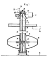
- Fig. 1 shows a side view of the measuring tube 2 of the device according to the invention in cross section.
- the measuring tube 2 is installed vertically in a tank 18.
- a magnetic float 14, 16 surrounds the measuring tube 2 with a sleeve 15 which is connected to the buoyancy body 16.
- a magnet 14 is arranged on the sleeve 15 at the level of the immersion level and protrudes into the buoyancy body 16.
- a cylindrical slide 20 made of magnetized or magnetizable material is displaceably arranged and is constantly held at the respective fill level of the tank 18 by the magnet 14 of the magnetic float 14, 16.
- the measuring tube 2 has a circular cross section.
- the slide 20 has the shape of a circular cylinder, the cylinder surface of which can be moved along the inner wall of the measuring tube 2 with little play.
- the measuring tube 2 is sealed gas-tight at the bottom by a lower cap 10 and at the top by an upper cap 12.
- two resistance elements are tensioned in the longitudinal direction of the measuring tube from the lower cap 10 to the upper cap 12 by means of a spring 27 which is anchored in the upper cap.
- the lower connections 30, 32 of the resistance elements are led upwards through the measuring tube 2 by means of a connecting line 35, and out through the upper cap 12.
- the upper connection end 28 of the first resistance element 24 is also passed through the upper cap via the spring 27.
- the upper end of the second resistance element 26 ends in the measuring tube.
- the slide 20 has a central bore or recess 22 through which the resistance elements 24, 26 pass.
- a first sliding contact 31 is provided on the slide 20 and rubs on the first resistance element 24.
- the sliding contacts 31, 33 are arranged in a horizontal plane which is aligned with the respective filling level.
- a third sliding contact 34 is attached to the slide 20 and rubs against the inner wall of the measuring tube 2 and is connected to the first and second sliding contacts 31, 33.
- the wall of the measuring tube 2 represents the supply line for the first and second sliding contact 31, 33 via the third sliding contact 34 and has a corresponding connecting terminal 36 at the upper end of the measuring tube. Movable supply lines within the measuring tube, which connect the outside space with the sliding sliding contacts 31, 33, can thus be omitted.
- the resistance elements consist of resistance wire, which is tightly wound on a band of insulating material. As a result, a high resolution of the tapped partial voltages, and thus a high measuring accuracy, is achieved.
- a temperature sensor 50 is arranged, which is followed by a temperature measuring circuit 52. If for any reason a further increase in the accuracy of the device according to the invention is desired, the temperature can be measured locally by means of the temperature sensor 50 at the upper end of the measuring tube. The total resistance of a resistance element can then be determined, for example in a preparatory measuring step, and the average temperature in the entire measuring tube can be determined therefrom. From the local temperature in the upper end of the measuring tube and the average temperature in the measuring tube, a linear temperature distribution can be calculated as a function of the location, and thus a corresponding linear function of the specific resistance depending on the location.
- the determination of the fill level x this linear function of the specific resistance depending on the location can then be used as a correction.
- the level is then obtained via a corresponding correction calculation, because due to the local change in the specific resistance, the measured partial voltage is no longer proportional to the level x. In practice, however, such a correction can generally be dispensed with.
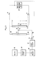
- Fig. 2 shows a block diagram of the device according to the invention.
- a reference voltage from a reference voltage source 40 in a first measuring step can be applied by means of a switch 41st
- a partial voltage is tapped between the first sliding contact 31, which is attached to the slide 20 (not shown), and the lower end connection 30 of the first resistance element 24 and is passed to the voltage measurement connection 43 of a measuring unit 42.
- the measuring unit 42 outputs a signal characterizing the measured voltage signal to an analog / digital converter 46, which forwards a suitable signal containing the measured information to a computer 48.
- the computer 48 conveys the tapped level x from the measured voltage value and emits a corresponding signal to a monitor 50.
- the switch 41 is flipped so that the reference voltage is now applied to the lower end connection 32 of the second resistance element 26.
- the circuit continues via the lower partial resistance Rx of the second resistance element 26 to the second sliding contact 33, which is at the same height as the first sliding contact 31.
- the circuit then leads to the resistance measuring connection 44 of the measuring unit 42, which determines the value of the partial resistance Rx.
- the measuring unit 42 outputs a corresponding signal to the analog / digital converter 46, which delivers a corresponding digital signal containing the information to the computer 48.
- the computer 48 calculates from the known ones Material data of the resistance element 26 as well as the previously stored fill level x the resistance R x and thereafter the mean temperature within the filling space zone to which the measured resistance R x is exposed.
Landscapes
- Physics & Mathematics (AREA)
- General Physics & Mathematics (AREA)
- Fluid Mechanics (AREA)
- Measurement Of Resistance Or Impedance (AREA)
- Measurement Of Levels Of Liquids Or Fluent Solid Materials (AREA)
- Level Indicators Using A Float (AREA)
- Waste-Gas Treatment And Other Accessory Devices For Furnaces (AREA)
- Arrangements For Transmission Of Measured Signals (AREA)
Priority Applications (1)
| Application Number | Priority Date | Filing Date | Title |
|---|---|---|---|
| AT81102681T ATE17784T1 (de) | 1980-04-28 | 1981-04-09 | Vorrichtung zur messung der fuellhoehe und der mittleren temperatur von fluessigkeiten in tankanlagen. |
Applications Claiming Priority (2)
| Application Number | Priority Date | Filing Date | Title |
|---|---|---|---|
| DE3016690A DE3016690C2 (de) | 1980-04-28 | 1980-04-28 | Längen- und Temperaturmeßgerät für Tankanlagen |
| DE3016690 | 1980-04-28 |
Publications (3)
| Publication Number | Publication Date |
|---|---|
| EP0039420A2 true EP0039420A2 (fr) | 1981-11-11 |
| EP0039420A3 EP0039420A3 (en) | 1983-02-09 |
| EP0039420B1 EP0039420B1 (fr) | 1986-01-29 |
Family
ID=6101365
Family Applications (1)
| Application Number | Title | Priority Date | Filing Date |
|---|---|---|---|
| EP81102681A Expired EP0039420B1 (fr) | 1980-04-28 | 1981-04-09 | Dispositif pour mesurer le niveau et la température moyenne de liquides en citernes |
Country Status (5)
| Country | Link |
|---|---|
| EP (1) | EP0039420B1 (fr) |
| AT (1) | ATE17784T1 (fr) |
| CA (1) | CA1156853A (fr) |
| DE (1) | DE3016690C2 (fr) |
| ZA (1) | ZA812753B (fr) |
Cited By (7)
| Publication number | Priority date | Publication date | Assignee | Title |
|---|---|---|---|---|
| FR2538105A1 (fr) * | 1981-06-25 | 1984-06-22 | Gluckauf Maschinenfabrik Beuke | Sonde de mesure pour cuves de stockage en particulier de liquides inflammables |
| FR2548362A1 (fr) * | 1983-06-29 | 1985-01-04 | Jaeger | Dispositif d'alarme de niveau de liquide a sonde resistive |
| FR2578049A1 (fr) * | 1985-02-25 | 1986-08-29 | Jaeger | Dispositif perfectionne de mesure du niveau de liquide dans un reservoir a indexation sur le fond |
| FR2601772A1 (fr) * | 1986-07-21 | 1988-01-22 | Unimess Messtech Geraete | Sonde de mesure de temperature |
| EP0321485A4 (en) * | 1986-09-03 | 1991-08-21 | Mts Systems Corporation | Distance and temperature measuring system for remote locations |
| WO1998017974A1 (fr) * | 1996-10-18 | 1998-04-30 | Data Instruments, Inc. | Capteur de position a couplage magnetique |
| CN111256033A (zh) * | 2020-01-20 | 2020-06-09 | 北京航天试验技术研究所 | 一种用于测量液氢贮箱中温度场的展开机构 |
Families Citing this family (4)
| Publication number | Priority date | Publication date | Assignee | Title |
|---|---|---|---|---|
| AT394273B (de) * | 1985-12-30 | 1992-02-25 | Enfo Grundlagen Forschungs Ag | Wegmesseinrichtung fuer ein in einem gehaeuse bewegbares bauelement |
| DE3926552A1 (de) * | 1989-08-11 | 1991-02-14 | Bayerische Motoren Werke Ag | Fuellstandssensor fuer kraftstoffbehaelter |
| DE102004046780B4 (de) * | 2004-09-27 | 2007-04-26 | Siemens Ag | Verfahren zur Funktionsprüfer eines Füllstandssensors |
| CN102901547A (zh) * | 2012-09-19 | 2013-01-30 | 樊荣 | 一种电接触式液位计 |
Family Cites Families (5)
| Publication number | Priority date | Publication date | Assignee | Title |
|---|---|---|---|---|
| DE1182875B (de) * | 1958-03-04 | 1964-12-03 | British Petroleum Co | Temperaturmessvorrichtung zur Bestimmung der mittleren Temperatur in einem Fluessigkeitstank |
| DE1548903B1 (de) * | 1965-12-02 | 1970-05-06 | Bertram Fab Ernst & Wilhelm | Geraet zum Messen einer in einem Behaelter befindlichen Fluessigkeit |
| US3653262A (en) * | 1970-10-22 | 1972-04-04 | Metritake Inc | Temperature and level sensor |
| DE2353171A1 (de) * | 1973-10-24 | 1975-05-07 | Oskar Luehn | Niveaustand-fernanzeiger fuer alle tropfbar fluessige koerper, z.b. fuer dampfkessel |
| US4158964A (en) * | 1978-05-10 | 1979-06-26 | The Foxboro Company | Method and apparatus for determining liquid level |
-
1980
- 1980-04-28 DE DE3016690A patent/DE3016690C2/de not_active Expired
-
1981
- 1981-04-09 AT AT81102681T patent/ATE17784T1/de active
- 1981-04-09 EP EP81102681A patent/EP0039420B1/fr not_active Expired
- 1981-04-27 ZA ZA00812753A patent/ZA812753B/xx unknown
- 1981-04-28 CA CA000376410A patent/CA1156853A/fr not_active Expired
Cited By (7)
| Publication number | Priority date | Publication date | Assignee | Title |
|---|---|---|---|---|
| FR2538105A1 (fr) * | 1981-06-25 | 1984-06-22 | Gluckauf Maschinenfabrik Beuke | Sonde de mesure pour cuves de stockage en particulier de liquides inflammables |
| FR2548362A1 (fr) * | 1983-06-29 | 1985-01-04 | Jaeger | Dispositif d'alarme de niveau de liquide a sonde resistive |
| FR2578049A1 (fr) * | 1985-02-25 | 1986-08-29 | Jaeger | Dispositif perfectionne de mesure du niveau de liquide dans un reservoir a indexation sur le fond |
| FR2601772A1 (fr) * | 1986-07-21 | 1988-01-22 | Unimess Messtech Geraete | Sonde de mesure de temperature |
| EP0321485A4 (en) * | 1986-09-03 | 1991-08-21 | Mts Systems Corporation | Distance and temperature measuring system for remote locations |
| WO1998017974A1 (fr) * | 1996-10-18 | 1998-04-30 | Data Instruments, Inc. | Capteur de position a couplage magnetique |
| CN111256033A (zh) * | 2020-01-20 | 2020-06-09 | 北京航天试验技术研究所 | 一种用于测量液氢贮箱中温度场的展开机构 |
Also Published As
| Publication number | Publication date |
|---|---|
| CA1156853A (fr) | 1983-11-15 |
| ZA812753B (en) | 1982-04-28 |
| EP0039420B1 (fr) | 1986-01-29 |
| ATE17784T1 (de) | 1986-02-15 |
| EP0039420A3 (en) | 1983-02-09 |
| DE3016690C2 (de) | 1986-01-09 |
| DE3016690A1 (de) | 1981-11-05 |
Similar Documents
| Publication | Publication Date | Title |
|---|---|---|
| DE2408124C3 (de) | Vorrichtung zum Messen von Flüssigkeitsständen | |
| EP0039420A2 (fr) | Dispositif pour mesurer le niveau et la température moyenne de liquides en citernes | |
| DE2501812A1 (de) | Gleichstromsystem zur leitfaehigkeitsmessung | |
| DE2449097C3 (de) | Meßumformer zur kapazitiven Füllstandsmessung von Flüssigkeitsfüllungen | |
| WO1996035929A1 (fr) | Detecteur capacitif de niveau | |
| DE2631533A1 (de) | Induktive messeinrichtung fuer fluessigmetallspiegel | |
| CH658720A5 (de) | Messsonde fuer lagerbehaelter. | |
| DE2717301B1 (de) | Messumformer zur kapazitiven Fuellstandsmessung von Fluessigkeitsfuellungen | |
| DE1238096B (de) | Vorrichtung zur Messung des Strom-Zeitintegrals | |
| DE4312813C2 (de) | Anordnung zur kapazitiven Füllstandsmessung | |
| DE2723999C2 (de) | Einrichtung zum elektrischen Messen der Standhöhe von elektrisch leitenden Flüssigkeiten | |
| EP0927877B1 (fr) | Dispositif de mesure pour une jauge carburant | |
| DE1473132A1 (de) | Pegelstandsanzeige-Einrichtung | |
| DE1598097C3 (de) | Einrichtung zum Anzeigen des Salzgehalts eines Gewässers | |
| DE3201643A1 (de) | Vorrichtung zur ortung eines feuchtigkeitseinbruches in einen langgestreckten gegenstand grosser ausdehnung | |
| DE844353C (de) | OElstandanzeiger fuer Kraftfahrzeugmotoren | |
| DE2803912C3 (de) | Einrichtung zur Gewinnung eines der Dichte einer elektrisch leitenden Flüssigkeit proportionalen elektrischen Meßsignals | |
| DE2700229A1 (de) | Fuellstandsmesseinrichtung | |
| DE1094992B (de) | Fluessigkeitsstandanzeiger | |
| DE3220635A1 (de) | Messvorrichtung | |
| DE1648156C3 (de) | Anordnung zur Füllstandmessung | |
| DE4220440A1 (de) | Messfuehlorgan oder sensor zum nachweis von gas-fluessigkeits-stroemungen | |
| DE4217658B4 (de) | Sensor zur Feststellung der Neigung und Verfahren zur Bestimmung einer Neigung | |
| DE3247205C2 (de) | Vorrichtung zur Feststellung von mineralischen Leichtflüssigkeitsschichten auf stehenden und fließenden Gewässern | |
| DE2446907A1 (de) | Induktives inhalts-fernanzeige-geraet fuer fluessigkeiten |
Legal Events
| Date | Code | Title | Description |
|---|---|---|---|
| PUAI | Public reference made under article 153(3) epc to a published international application that has entered the european phase |
Free format text: ORIGINAL CODE: 0009012 |
|
| AK | Designated contracting states |
Designated state(s): AT BE CH FR GB IT LI LU NL SE |
|
| PUAL | Search report despatched |
Free format text: ORIGINAL CODE: 0009013 |
|
| AK | Designated contracting states |
Designated state(s): AT BE CH FR GB IT LI LU NL SE |
|
| RHK1 | Main classification (correction) |
Ipc: G01K 3/06 |
|
| 17P | Request for examination filed |
Effective date: 19830224 |
|
| RAP1 | Party data changed (applicant data changed or rights of an application transferred) |
Owner name: BK ELEKTRONIK MESSGERAETE GMBH |
|
| RIN1 | Information on inventor provided before grant (corrected) |
Inventor name: RAPP, EUGEN |
|
| GRAA | (expected) grant |
Free format text: ORIGINAL CODE: 0009210 |
|
| AK | Designated contracting states |
Designated state(s): AT BE CH FR GB IT LI LU NL SE |
|
| REF | Corresponds to: |
Ref document number: 17784 Country of ref document: AT Date of ref document: 19860215 Kind code of ref document: T |
|
| ITF | It: translation for a ep patent filed | ||
| ET | Fr: translation filed | ||
| PG25 | Lapsed in a contracting state [announced via postgrant information from national office to epo] |
Ref country code: LU Free format text: LAPSE BECAUSE OF NON-PAYMENT OF DUE FEES Effective date: 19860430 |
|
| PGFP | Annual fee paid to national office [announced via postgrant information from national office to epo] |
Ref country code: AT Payment date: 19860528 Year of fee payment: 6 |
|
| PLBE | No opposition filed within time limit |
Free format text: ORIGINAL CODE: 0009261 |
|
| STAA | Information on the status of an ep patent application or granted ep patent |
Free format text: STATUS: NO OPPOSITION FILED WITHIN TIME LIMIT |
|
| 26N | No opposition filed | ||
| PG25 | Lapsed in a contracting state [announced via postgrant information from national office to epo] |
Ref country code: AT Effective date: 19870409 |
|
| PG25 | Lapsed in a contracting state [announced via postgrant information from national office to epo] |
Ref country code: SE Effective date: 19870410 |
|
| PG25 | Lapsed in a contracting state [announced via postgrant information from national office to epo] |
Ref country code: LI Effective date: 19870430 Ref country code: CH Effective date: 19870430 |
|
| PGFP | Annual fee paid to national office [announced via postgrant information from national office to epo] |
Ref country code: NL Payment date: 19870430 Year of fee payment: 7 |
|
| PG25 | Lapsed in a contracting state [announced via postgrant information from national office to epo] |
Ref country code: FR Free format text: LAPSE BECAUSE OF NON-PAYMENT OF DUE FEES Effective date: 19871230 |
|
| REG | Reference to a national code |
Ref country code: CH Ref legal event code: PL |
|
| REG | Reference to a national code |
Ref country code: FR Ref legal event code: ST |
|
| BERE | Be: lapsed |
Owner name: BK ELEKTRONIK MESSGERATE G.M.B.H. Effective date: 19880430 |
|
| PG25 | Lapsed in a contracting state [announced via postgrant information from national office to epo] |
Ref country code: NL Effective date: 19881101 |
|
| PG25 | Lapsed in a contracting state [announced via postgrant information from national office to epo] |
Ref country code: GB Effective date: 19881118 |
|
| NLV4 | Nl: lapsed or anulled due to non-payment of the annual fee | ||
| GBPC | Gb: european patent ceased through non-payment of renewal fee | ||
| PG25 | Lapsed in a contracting state [announced via postgrant information from national office to epo] |
Ref country code: BE Effective date: 19890430 |
|
| EUG | Se: european patent has lapsed |
Ref document number: 81102681.4 Effective date: 19871110 |