EP0039668A1 - Vorrichtung zur Leitung eines Flüssigkeitsteilstromes aus einer Rohrleitung - Google Patents
Vorrichtung zur Leitung eines Flüssigkeitsteilstromes aus einer Rohrleitung Download PDFInfo
- Publication number
- EP0039668A1 EP0039668A1 EP81850080A EP81850080A EP0039668A1 EP 0039668 A1 EP0039668 A1 EP 0039668A1 EP 81850080 A EP81850080 A EP 81850080A EP 81850080 A EP81850080 A EP 81850080A EP 0039668 A1 EP0039668 A1 EP 0039668A1
- Authority
- EP
- European Patent Office
- Prior art keywords
- conduit
- container
- fluid
- flow channel
- inlet
- Prior art date
- Legal status (The legal status is an assumption and is not a legal conclusion. Google has not performed a legal analysis and makes no representation as to the accuracy of the status listed.)
- Ceased
Links
- 239000012530 fluid Substances 0.000 title claims abstract description 17
- 238000005259 measurement Methods 0.000 claims abstract description 10
- 210000002105 tongue Anatomy 0.000 abstract description 9
- 239000008267 milk Substances 0.000 description 3
- 235000013336 milk Nutrition 0.000 description 3
- 210000004080 milk Anatomy 0.000 description 3
- 235000013365 dairy product Nutrition 0.000 description 2
- 239000011521 glass Substances 0.000 description 2
- 239000007788 liquid Substances 0.000 description 2
- 239000008237 rinsing water Substances 0.000 description 2
- 239000002699 waste material Substances 0.000 description 2
- 238000009434 installation Methods 0.000 description 1
- 238000004519 manufacturing process Methods 0.000 description 1
- 239000000463 material Substances 0.000 description 1
- 238000012986 modification Methods 0.000 description 1
- 230000004048 modification Effects 0.000 description 1
- 238000007789 sealing Methods 0.000 description 1
- 238000005406 washing Methods 0.000 description 1
- XLYOFNOQVPJJNP-UHFFFAOYSA-N water Substances O XLYOFNOQVPJJNP-UHFFFAOYSA-N 0.000 description 1
Images
Classifications
-
- G—PHYSICS
- G01—MEASURING; TESTING
- G01N—INVESTIGATING OR ANALYSING MATERIALS BY DETERMINING THEIR CHEMICAL OR PHYSICAL PROPERTIES
- G01N1/00—Sampling; Preparing specimens for investigation
- G01N1/02—Devices for withdrawing samples
- G01N1/10—Devices for withdrawing samples in the liquid or fluent state
- G01N1/20—Devices for withdrawing samples in the liquid or fluent state for flowing or falling materials
- G01N1/2035—Devices for withdrawing samples in the liquid or fluent state for flowing or falling materials by deviating part of a fluid stream, e.g. by drawing-off or tapping
Definitions
- the present invention relates to an apparatus for deflecting a partial fluid flow from a conduit to an area where measurements are made on the fluid.
- the object of the present invention is to provide an apparatus by means of which the above-mentioned disadvantages have been circumvented.
- the foremost advantages of the apparatus in accordance with the invention is that it is easy and cheap to manufacture, it is simple to fit to a pipe, and movable from one test point to another, it gives small flow resistance, and does not cause any measurement lag, the turbidity of a liquid can be measured without the measuring apparatus being subjected to the effect of heat, coolers or similar auxiliary equipment do.not need to be used, and the liquid on which measurement is carried out is immediately returned to the pipe after measurement.
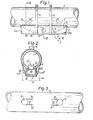
- a part of a conduit e.g. for conveying milk in a dairy, is denoted on the figures by the numeral 1.
- an apparatus in accordance with the invention has been fitted to the conduit.
- the apparatus has the form of a parallelepipedic box 2 with an upwardly open side, the edges of which engage sealingly against the cylindrical surface of the conduit 1 via rectangular, closed, sealing ring 3.
- the box 2 is fitted to the underside of the conduit 1, but if so desired it can be fitted to one side thereof instead. However, to prevent air bubbles forming in the box, the greater part of it should be situated under the longitudinal axis of conduit 1.
- the box 2 is removably attached to the conduit 1 by means of hose clips 4 and 5..
- each hole has been provided with two slits 8, 9 and 10, 11, respectively, each pair of slits defining a tongue 12 and 13, respectively, which is bent in towards the centre of the conduit 1.
- the box 2 is fitted to the conduit such that the holes 6, 7 and tongues 12, 13 come within the walls of the box in the vicinity of its end walls 2a and 2b, as shown in Figure 1.
- a continuously curved plate 14 is fixed inside the box 2, to form'a wall for a through flow channel 15, the remaining walls of which are formed by the cylindrical surface of the conduit between the tongues 11, 13 and portions of the opposing side walls of the box parallel to the conduit.
- Sight glasses 16 and 17 are sealingly inserted in holes opposite each other in the side walls of the box, which are parallel to the conduit.
- a turbidity meter of known type e.g. one sold under the name of Turbidimeter, type ATM 20, by Cerlic Electronics AB, Solna, Sweden, can be used for measuring the turbidity of the fluid flowing through the channel 15.
- Such a meter includes a U-shaped measuring part M, schematically illustrated in Figure 2, which is mounted over the box 2 so that its light-emitting and -receiving means m 1 and m 2 come in the centre of the sight glasses 16 and 17.
- a meter E e.g. a pH, redox or conductivity meter, with an electrode e, thrusting into the channel 15, is attached to the bottom of the box 2 and is schematically illustrated in Figure 2. If so desired, several meters of the kind mentioned or. of some other kind can naturally be removably or permanently mounted on the box 2, for carrying out measurements on the fluid flowing through the channel 15.
Landscapes
- Life Sciences & Earth Sciences (AREA)
- Hydrology & Water Resources (AREA)
- Physics & Mathematics (AREA)
- Health & Medical Sciences (AREA)
- Chemical & Material Sciences (AREA)
- Analytical Chemistry (AREA)
- Biochemistry (AREA)
- General Health & Medical Sciences (AREA)
- General Physics & Mathematics (AREA)
- Immunology (AREA)
- Pathology (AREA)
- Optical Measuring Cells (AREA)
- Investigating Or Analysing Materials By Optical Means (AREA)
Applications Claiming Priority (2)
| Application Number | Priority Date | Filing Date | Title |
|---|---|---|---|
| SE8003387 | 1980-05-06 | ||
| SE8003387A SE421651B (sv) | 1980-05-06 | 1980-05-06 | Anordning for att avleda en delfluidstrom fran en ledning |
Publications (1)
| Publication Number | Publication Date |
|---|---|
| EP0039668A1 true EP0039668A1 (de) | 1981-11-11 |
Family
ID=20340909
Family Applications (1)
| Application Number | Title | Priority Date | Filing Date |
|---|---|---|---|
| EP81850080A Ceased EP0039668A1 (de) | 1980-05-06 | 1981-05-06 | Vorrichtung zur Leitung eines Flüssigkeitsteilstromes aus einer Rohrleitung |
Country Status (2)
| Country | Link |
|---|---|
| EP (1) | EP0039668A1 (de) |
| SE (1) | SE421651B (de) |
Cited By (3)
| Publication number | Priority date | Publication date | Assignee | Title |
|---|---|---|---|---|
| DE3546354A1 (de) * | 1985-12-30 | 1987-07-02 | Schleicher Leonhard | Ventil und dessen montage |
| WO1988007667A1 (en) * | 1987-03-26 | 1988-10-06 | Ryan Rosenberg | A method of and an apparatus for taking a sample from a fluid flowing through a conduit |
| FR2708347A1 (fr) * | 1993-07-01 | 1995-02-03 | Syclope Electronique | Chambre de mesure, notamment pour le contrôle de l'eau d'une piscine. |
Citations (6)
| Publication number | Priority date | Publication date | Assignee | Title |
|---|---|---|---|---|
| US2800869A (en) * | 1956-01-04 | 1957-07-30 | Alvis L Barrier | Fluid flow line inspection device |
| US3665201A (en) * | 1968-12-23 | 1972-05-23 | Gam Rad | Turbidimeter utilizing back scatter |
| US3713743A (en) * | 1970-11-25 | 1973-01-30 | Agricultural Control Syst | Forward scatter optical turbidimeter apparatus |
| US4018089A (en) * | 1976-05-05 | 1977-04-19 | Beckman Instruments, Inc. | Fluid sampling apparatus |
| US4113390A (en) * | 1977-03-14 | 1978-09-12 | Bindicator Company | Optical sight tube for fluid conduits |
| US4167117A (en) * | 1978-07-10 | 1979-09-11 | Exxon Production Research Company | Apparatus and method for sampling flowing fluids and slurries |
-
1980
- 1980-05-06 SE SE8003387A patent/SE421651B/sv not_active IP Right Cessation
-
1981
- 1981-05-06 EP EP81850080A patent/EP0039668A1/de not_active Ceased
Patent Citations (6)
| Publication number | Priority date | Publication date | Assignee | Title |
|---|---|---|---|---|
| US2800869A (en) * | 1956-01-04 | 1957-07-30 | Alvis L Barrier | Fluid flow line inspection device |
| US3665201A (en) * | 1968-12-23 | 1972-05-23 | Gam Rad | Turbidimeter utilizing back scatter |
| US3713743A (en) * | 1970-11-25 | 1973-01-30 | Agricultural Control Syst | Forward scatter optical turbidimeter apparatus |
| US4018089A (en) * | 1976-05-05 | 1977-04-19 | Beckman Instruments, Inc. | Fluid sampling apparatus |
| US4113390A (en) * | 1977-03-14 | 1978-09-12 | Bindicator Company | Optical sight tube for fluid conduits |
| US4167117A (en) * | 1978-07-10 | 1979-09-11 | Exxon Production Research Company | Apparatus and method for sampling flowing fluids and slurries |
Cited By (3)
| Publication number | Priority date | Publication date | Assignee | Title |
|---|---|---|---|---|
| DE3546354A1 (de) * | 1985-12-30 | 1987-07-02 | Schleicher Leonhard | Ventil und dessen montage |
| WO1988007667A1 (en) * | 1987-03-26 | 1988-10-06 | Ryan Rosenberg | A method of and an apparatus for taking a sample from a fluid flowing through a conduit |
| FR2708347A1 (fr) * | 1993-07-01 | 1995-02-03 | Syclope Electronique | Chambre de mesure, notamment pour le contrôle de l'eau d'une piscine. |
Also Published As
| Publication number | Publication date |
|---|---|
| SE421651B (sv) | 1982-01-18 |
| SE8003387L (sv) | 1981-11-07 |
Similar Documents
| Publication | Publication Date | Title |
|---|---|---|
| US3801077A (en) | Humidifying apparatus | |
| GB2052741A (en) | Measurement value generators for determining the through-flow rate of a flowing fluid | |
| KR960021125A (ko) | 희석액을 화학약품과 배합하는 장치 | |
| US8881579B2 (en) | Method and device for determining viscosity utilizing gravity feed | |
| JPS57207826A (en) | Measuring device for flow rate of pulverulent body | |
| FI109310B (fi) | Laite ja menetelmä epätasaisessa virtauksessa tulevien nestemäisten aineiden määrän mittaamiseksi | |
| JPH0569630U (ja) | 流体の流量測定装置 | |
| GB8321482D0 (en) | Flowmeter | |
| IE47572B1 (en) | Apparatus for cleaning a container | |
| ATE285065T1 (de) | Vorrichtung zur messung einer volumenflüssigkeitsströmung in einem rohr | |
| KR100445393B1 (ko) | 유량측정장치 | |
| US4232703A (en) | Safety close-off valve arrangement for pipe conduit systems and installations | |
| SE421651B (sv) | Anordning for att avleda en delfluidstrom fran en ledning | |
| US1943039A (en) | Proportioning and feeding device | |
| GB860043A (en) | Means and method for extracting true proportionate sample of fluid material | |
| US4741216A (en) | Split flowtube for molten metal magnetic flowmeter | |
| ATE93360T1 (de) | Messvorrichtung. | |
| FI66225B (fi) | Dekontaminerande uttagsanordning foer destillerat vatten | |
| JPH11248507A (ja) | 簡易流量積算計及び流量積算方法 | |
| SU800647A1 (ru) | Расходомер жидкости | |
| SE8106237L (sv) | Luftningsanordning | |
| SU830122A1 (ru) | Расходомер дл жидкости | |
| DE3377428D1 (en) | Heat and mass exchange apparatus between liquids and gases or vapours | |
| KR900005164A (ko) | 유동측정기 | |
| CZ117193A3 (cs) | Způsob sledování funkce dávkovacího čerpadla a měrný člen k provádění způsobu |
Legal Events
| Date | Code | Title | Description |
|---|---|---|---|
| PUAI | Public reference made under article 153(3) epc to a published international application that has entered the european phase |
Free format text: ORIGINAL CODE: 0009012 |
|
| AK | Designated contracting states |
Designated state(s): CH DE FR GB NL |
|
| 17P | Request for examination filed |
Effective date: 19820507 |
|
| STAA | Information on the status of an ep patent application or granted ep patent |
Free format text: STATUS: THE APPLICATION HAS BEEN REFUSED |
|
| 18R | Application refused |
Effective date: 19840329 |
|
| RIN1 | Information on inventor provided before grant (corrected) |
Inventor name: JONSSON, ROLF AKE |