EP0039669A2 - Filtre à air électrostatique - Google Patents
Filtre à air électrostatique Download PDFInfo
- Publication number
- EP0039669A2 EP0039669A2 EP81890074A EP81890074A EP0039669A2 EP 0039669 A2 EP0039669 A2 EP 0039669A2 EP 81890074 A EP81890074 A EP 81890074A EP 81890074 A EP81890074 A EP 81890074A EP 0039669 A2 EP0039669 A2 EP 0039669A2
- Authority
- EP
- European Patent Office
- Prior art keywords
- plates
- flow
- potential
- ions
- voltage
- Prior art date
- Legal status (The legal status is an assumption and is not a legal conclusion. Google has not performed a legal analysis and makes no representation as to the accuracy of the status listed.)
- Granted
Links
Images

Classifications
-
- B—PERFORMING OPERATIONS; TRANSPORTING
- B03—SEPARATION OF SOLID MATERIALS USING LIQUIDS OR USING PNEUMATIC TABLES OR JIGS; MAGNETIC OR ELECTROSTATIC SEPARATION OF SOLID MATERIALS FROM SOLID MATERIALS OR FLUIDS; SEPARATION BY HIGH-VOLTAGE ELECTRIC FIELDS
- B03C—MAGNETIC OR ELECTROSTATIC SEPARATION OF SOLID MATERIALS FROM SOLID MATERIALS OR FLUIDS; SEPARATION BY HIGH-VOLTAGE ELECTRIC FIELDS
- B03C3/00—Separating dispersed particles from gases or vapour, e.g. air, by electrostatic effect
- B03C3/02—Plant or installations having external electricity supply
- B03C3/04—Plant or installations having external electricity supply dry type
- B03C3/12—Plant or installations having external electricity supply dry type characterised by separation of ionising and collecting stations
-
- B—PERFORMING OPERATIONS; TRANSPORTING
- B03—SEPARATION OF SOLID MATERIALS USING LIQUIDS OR USING PNEUMATIC TABLES OR JIGS; MAGNETIC OR ELECTROSTATIC SEPARATION OF SOLID MATERIALS FROM SOLID MATERIALS OR FLUIDS; SEPARATION BY HIGH-VOLTAGE ELECTRIC FIELDS
- B03C—MAGNETIC OR ELECTROSTATIC SEPARATION OF SOLID MATERIALS FROM SOLID MATERIALS OR FLUIDS; SEPARATION BY HIGH-VOLTAGE ELECTRIC FIELDS
- B03C3/00—Separating dispersed particles from gases or vapour, e.g. air, by electrostatic effect
- B03C3/02—Plant or installations having external electricity supply
- B03C3/16—Plant or installations having external electricity supply wet type
-
- B—PERFORMING OPERATIONS; TRANSPORTING
- B03—SEPARATION OF SOLID MATERIALS USING LIQUIDS OR USING PNEUMATIC TABLES OR JIGS; MAGNETIC OR ELECTROSTATIC SEPARATION OF SOLID MATERIALS FROM SOLID MATERIALS OR FLUIDS; SEPARATION BY HIGH-VOLTAGE ELECTRIC FIELDS
- B03C—MAGNETIC OR ELECTROSTATIC SEPARATION OF SOLID MATERIALS FROM SOLID MATERIALS OR FLUIDS; SEPARATION BY HIGH-VOLTAGE ELECTRIC FIELDS
- B03C3/00—Separating dispersed particles from gases or vapour, e.g. air, by electrostatic effect
- B03C3/34—Constructional details or accessories or operation thereof
- B03C3/40—Electrode constructions
Definitions
- the invention relates to an electrostatic air filter with an ionization part and a separating part which is composed of separating plates which are alternately under high voltage and earthed.
- the invention further relates to an electrostatic AC fan.
- the first-mentioned invention has the task of making the devices cheaper by simplification.
- Electrical air filter devices such as those used predominantly in the household, have an ionization part and a separating part.
- the ionization part usually consists of discharge electrodes, preferably thin wires at a corresponding high voltage potential, and counter electrodes, which are generally at ground potential and thus define an electric field with the discharge electrodes, which leads to the formation of ions around the discharge electrodes.
- one of the two types of ions is repelled by the discharge electrode and attaches itself to the aerosols in the air while the air flows to the separating part of the device.
- the separating part of the device generally consists of electrically conductive plates which are arranged parallel to one another and which are alternately at ground potential and at high voltage potential, so that an electrical field is formed between them in which the charged dust Particles migrate to the corresponding plate and are deposited there.
- a wire-shaped discharge electrode generally requires voltages between 12 and 15 kV, while the deposition part plate voltages: between 3 and 6 kV.
- the separation voltage of 6 kV is only used in combinations with the 12 kV ionization voltage, since then the production of two different high voltages is simply done via a transformer with a 6 kV peak voltage and two rectifiers, which work for the discharge electrode in a voltage doubling circuit.
- the disadvantages bought with it are unfortunately very large. Separation plates that can withstand a voltage of 6 kV not only have to be particularly well insulated, they also have to be far apart. This leads to an expensive construction and a large space requirement, since an appropriate plate surface must be available for the separation of a certain amount of dust.
- the generation of positive ions is more advantageous in an air filter device and it is also less expensive to use the same high voltage, or at least part of it, to charge the one type of plate.
- a disadvantage of the known air filter devices lies in the fact that the positively charged aerosol can never be completely collected and the air is systematically positively charged. This process is intensified by the fact that the few negative ions present in the air are also largely deposited on the plates.
- the invention also has the task of designing the known electrostatic alternating current blowers in such a way that they can be operated with high-voltage alternating current and / or simultaneously use ions of both signs to produce the blower effect.
- the high-voltage genus of the separating plates is fastened in a completely insulated manner and is not conductively connected to any defined potential, except preferably with other plates of the same genus, and that the high voltage of these plates is only by their position and their distance from the discharge electrodes of the ionization part is determined.
- the separating plates mentioned do not obtain their high voltage from an electronic circuit, but rather from the field between the discharge electrode and the counterelectrode, in that the ends of these separating plates extend so far into the field that they draw the charge from the field or with the help of the ions moving in it, which they need to maintain the corresponding separating voltage.
- wires are tensioned between the separating plates which are at a positive high voltage and parallel to them, which are in the vicinity or at ground potential and are preferably arranged at the end of the separating plates as seen in the direction of flow.
- the invention proposes that the counter electrode, discharge electrode and preferably auxiliary electrode, which are necessary for generating a directed flow, and which are known per se, can be operated with high-voltage alternating current, since these electrodes are seen in the direction of flow are arranged at intervals which are in relation to one another and to the flow velocities of the gases or the drift velocities of the ions in the gases at predetermined alternating current frequencies in very specific ratios, in particular that the distance between the discharge and counter electrodes at a predetermined frequency is relative to the flow velocity of the gas or the drift velocity of the ions in the gas is in a very specific ratio, in particular that the smallest of these velocities is greater or comparable to the product of the frequency and the distance of the discharge from the counterelectrode.
- a preferred embodiment of the device has a number of blower stages arranged one behind the other, whereby the coordination of the electrode spacings and the flow velocity of the gases or the drift velocity of the ions leads to a resonance effect which permits higher blower outputs or the establishment of a larger pressure difference.
- unipolar charged liquid aerosol is generated by a known high-voltage nozzle or one or more nozzles with a downstream discharge path and by the geometry of the high-voltage nozzle or charging electrode and a suitable counterelectrode is forced to earth potential, preferably to move in one direction or at least in the direction of a cone with an opening angle of less than 90 °, in particular when the direction and energy of the liquid drops, which is predetermined by a nozzle, is consumed, the electro-aerosol being a stretch of at least 20 to 30 mm and a potential difference of 10 to 30 kV, preferably 15 to 25 kV, in order to be able to take along correspondingly large amounts of air on the way to the downstream counter electrode.
- the nozzle or charging electrode can also be at earth potential, while the counter electrode can be at high voltage potential.
- the power consumption of such an aerosol blower essentially consists in the generation of the high voltage at a specific current, which specifies the number of migrating ions. If the formation of the electro-aerosol ensures that each ion sits on a drop of liquid as it is being formed, maximum internal air friction and thus optimum efficiency are ensured for the charge to migrate to the counter electrode.
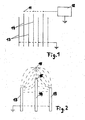
- FIG. 1 shows the geometric arrangement and the circuit diagram of a particular embodiment of the first mentioned invention
- Fig. 2 is an enlarged detail of the arrangement shown in Fig. 1 with an indicated course of the field lines .
- Fig. 3 schematically shows a preferred embodiment of the invention mentioned in the second place.
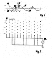
- 4 and 5 show a schematic proposal for a device according to the invention, wherein on the one hand the concentration of positive and negative ions at the time of the greatest field strength in a series connection of fan stages consisting of wires and on the other hand the arrangement of these wires and their electrical supply are shown.
- Fig. 1 the discharge wires 11 shown in section are brought to a potential of about 12 kV by the high voltage source 12.
- FIG. 2 shows an enlarged detail of the exemplary embodiment described in FIG. 1 with an indicated field line course, from which the mode of operation of the invention can be seen.
- the field lines run from the discharge wire 11 to the grounded: separator plates 13.
- the isolated separator plate 14 will attract 15 field lines with its edge closest to the discharge wire 11 as long as its potential is below the potential prevailing at point 15 without a separator plate 14.
- Along. of these field lines will also hit the plate 14 from ions coming from the discharge wire 11 and charge until their edge 15 begins to repel the field lines coming from the discharge wire.
- This plate 14 will now hold its potential until some minority ions of the other polarity have discharged it to such an extent that it is again forced to pass over the points 15 closest to the discharge wire charge.
- the separating plate 14 endeavors to keep its potential exactly at the value which prevails at the point 15 when the plate 14 is removed. This makes it possible to set the separation voltage completely freely in a very large interval, for example between 2 kV and 10 kV, by selecting the distance between the plate 14 and the wire 11.
- the simplification of the electrostatic air filter according to the invention also works satisfactorily if it is a wet electrostatic precipitator in which the ions are released into the air via an electrically charged liquid aerosol.
- the measures proposed in this invention basically also work when a potential reflection is carried out, that is to say that the discharge electrode is at earth potential and the corresponding electric field is applied in that the counterelectrodes integrated in the separating plates are now at high voltage potential.
- the high field strength causing the discharge also arises in this case around the discharge electrodes, which have a special shape for this purpose, such as wire, tip, etc.
- the ions now have opposite polarity and the insulated plates not only not allowed to charge, but that they have to be charged with the now very rare homopolar ions so that their potential comes close to the high-voltage separating plates.
- This mechanism works in principle, but it can be supported by a discharge path between the two different types of separator plates.
- wires 22 are embedded in corresponding recesses in the earthed separating plates in such a way that they also have earth potential. The easiest way to do this is through points 23 with a spot welding machine. These wires 22 are therefore parallel to the high-voltage separating plates 24. Since it makes no difference to the electrical field on the wire 22 whether a wire at negative high voltage is opposite an earthed plate or an earthed wire is opposite a plate under positive high voltage, negative ions are generated on this grounded wire 22, which then preferably leave the separating plates with the air when the positive plates 24 are seen at the height of the wire 22 in the flow direction or, as shown in the drawing figure 3, immediately after the height of the wire 22 ends.
- the ionization part is not shown in Fig. 3. It usually consists of thin, high-tension wires.
- the amount of negative ions formed can be determined for a given plate voltage either by the wire diameter or by the width of the recess or by both. However, the position of the end edge of the positive plate also determines the quantity of ions formed in addition to the amount of ions emerging.
- a further variant according to the invention consists of laterally offset, successively arranged thick wires 25 and thin wires 26, which, viewed in the direction of flow, are arranged at equal intervals a. Electrically, a thick and a thin wire are in pairs at the same potential, these pairs being functionally connected to the two outputs of an alternating current source of high voltage, so that the counter electrode 27 of the preceding stage is identical to the auxiliary electrode of the 'following stage, which only has to ensure that the ions only move in one direction.
- the thin wires 26 are the discharge electrodes, on which positive and negative ions alternate.
- the wavy line 28 shows somewhat schematically the concentration of the positive (above the axis 29) and the negative ions (below the axis 29) after prolonged operation, whereby neither the ions hitting the counterelectrode nor the newly formed ones were taken into account in the continuous wave train, as this is only hinted at in the dashed line 30.
- blower stages are arranged side by side and one behind the other to form a network of wires of different thicknesses to form a large blower, as is shown in the normal section of the wires.
- the distances of all wires are the same in the projection onto the flow direction 31 and are a cm.
- v is to be understood as the drift velocity. This is then also not the same for all ions, since these accumulate on different gases and hydrate to different extents and / or accumulate on dust particles, so that v is understood to mean an average drift speed.
Landscapes
- Electrostatic Separation (AREA)
Applications Claiming Priority (8)
| Application Number | Priority Date | Filing Date | Title |
|---|---|---|---|
| AT2397/80 | 1980-05-06 | ||
| AT239780A AT372301B (de) | 1980-05-06 | 1980-05-06 | Elektrostatisches luftfilter |
| AT239880 | 1980-05-06 | ||
| AT2398/80 | 1980-05-06 | ||
| AT380880 | 1980-07-23 | ||
| AT3806/80 | 1980-07-23 | ||
| AT3808/80 | 1980-07-23 | ||
| AT380680 | 1980-07-23 |
Publications (3)
| Publication Number | Publication Date |
|---|---|
| EP0039669A2 true EP0039669A2 (fr) | 1981-11-11 |
| EP0039669A3 EP0039669A3 (en) | 1983-09-14 |
| EP0039669B1 EP0039669B1 (fr) | 1985-12-27 |
Family
ID=27421762
Family Applications (1)
| Application Number | Title | Priority Date | Filing Date |
|---|---|---|---|
| EP19810890074 Expired EP0039669B1 (fr) | 1980-05-06 | 1981-05-05 | Filtre à air électrostatique |
Country Status (2)
| Country | Link |
|---|---|
| EP (1) | EP0039669B1 (fr) |
| DE (1) | DE3173286D1 (fr) |
Cited By (10)
| Publication number | Priority date | Publication date | Assignee | Title |
|---|---|---|---|---|
| EP0114178A1 (fr) * | 1982-12-30 | 1984-08-01 | Nichiele Corporation | Appareil de purification d'air |
| DE3409999A1 (de) * | 1983-03-18 | 1984-09-20 | Ricoh Co., Ltd., Tokio/Tokyo | Einrichtung zum erzeugen eines ionenwindes |
| EP0125379A3 (fr) * | 1983-05-13 | 1985-05-15 | Endo, Keiko | Appareil pour engendrer une circulation d'air |
| US4689056A (en) * | 1983-11-23 | 1987-08-25 | Nippon Soken, Inc. | Air cleaner using ionic wind |
| DE19842068A1 (de) * | 1998-09-15 | 2000-03-16 | Brand Gerhart Rosemarie | Lufttechnische Anlage zum Transport von Luft in elektrostatischen Feldern |
| EP1033171A3 (fr) * | 1999-03-01 | 2001-03-28 | Heinz Aigner | Filtre electrostatique notamment pour le nettoyage de l'air d'échappement des tunnels routiers et d'autres choses semblables |
| WO2009059451A1 (fr) * | 2007-11-05 | 2009-05-14 | Su, Jiting | Précipitateur électrostatique |
| EP1948363A4 (fr) * | 2005-11-01 | 2011-04-27 | Roger Gale | Dispositif de precipitation electrostatique monoetage |
| CN106694228A (zh) * | 2016-11-18 | 2017-05-24 | 江苏智石科技有限公司 | 一种空气过滤装置 |
| CN109239052A (zh) * | 2018-10-29 | 2019-01-18 | 中国科学院上海技术物理研究所 | 基于液芯波导拉曼光谱的航天员尿液检测方法 |
Family Cites Families (11)
| Publication number | Priority date | Publication date | Assignee | Title |
|---|---|---|---|---|
| DE1127332B (de) * | 1955-08-30 | 1962-04-12 | Westinghouse Electric Corp | Elektrostatischer Abscheider |
| GB913172A (en) * | 1959-02-20 | 1962-12-19 | Guenter Hermann Wilhelm Jucho | Improvements in or relating to electrostatic filters |
| DE1679532B1 (de) * | 1967-10-09 | 1970-12-10 | Berckheim Graf Von | Anordnung zur Erzeugung unipolarer Luftionen |
| FR1593800A (fr) * | 1968-12-29 | 1970-06-01 | ||
| YU87570A (en) * | 1970-04-02 | 1973-12-31 | Iat Inst Aerodinamic Termodina | Elektronski uredaj za visoki napon |
| US3704572A (en) * | 1970-05-15 | 1972-12-05 | Gourdine Systems Inc | Electrostatic precipitator system |
| US3638058A (en) * | 1970-06-08 | 1972-01-25 | Robert S Fritzius | Ion wind generator |
| DE2052014A1 (de) * | 1970-10-23 | 1972-04-27 | Messerschmitt Boelkow Blohm | Ionentriebwerk |
| FR2282670A1 (fr) * | 1974-08-21 | 1976-03-19 | Equip Climatique | Regulateur pour installation d'electroclimatisation ionique |
| DE2448979A1 (de) * | 1974-10-15 | 1976-04-29 | Licentia Gmbh | Elektrostatisches luftfilter |
| AU525784B2 (en) * | 1978-03-02 | 1982-12-02 | Pontius, D.H. | Reducing back corona effects |
-
1981
- 1981-05-05 EP EP19810890074 patent/EP0039669B1/fr not_active Expired
- 1981-05-05 DE DE8181890074T patent/DE3173286D1/de not_active Expired
Cited By (10)
| Publication number | Priority date | Publication date | Assignee | Title |
|---|---|---|---|---|
| EP0114178A1 (fr) * | 1982-12-30 | 1984-08-01 | Nichiele Corporation | Appareil de purification d'air |
| DE3409999A1 (de) * | 1983-03-18 | 1984-09-20 | Ricoh Co., Ltd., Tokio/Tokyo | Einrichtung zum erzeugen eines ionenwindes |
| EP0125379A3 (fr) * | 1983-05-13 | 1985-05-15 | Endo, Keiko | Appareil pour engendrer une circulation d'air |
| US4689056A (en) * | 1983-11-23 | 1987-08-25 | Nippon Soken, Inc. | Air cleaner using ionic wind |
| DE19842068A1 (de) * | 1998-09-15 | 2000-03-16 | Brand Gerhart Rosemarie | Lufttechnische Anlage zum Transport von Luft in elektrostatischen Feldern |
| EP1033171A3 (fr) * | 1999-03-01 | 2001-03-28 | Heinz Aigner | Filtre electrostatique notamment pour le nettoyage de l'air d'échappement des tunnels routiers et d'autres choses semblables |
| EP1948363A4 (fr) * | 2005-11-01 | 2011-04-27 | Roger Gale | Dispositif de precipitation electrostatique monoetage |
| WO2009059451A1 (fr) * | 2007-11-05 | 2009-05-14 | Su, Jiting | Précipitateur électrostatique |
| CN106694228A (zh) * | 2016-11-18 | 2017-05-24 | 江苏智石科技有限公司 | 一种空气过滤装置 |
| CN109239052A (zh) * | 2018-10-29 | 2019-01-18 | 中国科学院上海技术物理研究所 | 基于液芯波导拉曼光谱的航天员尿液检测方法 |
Also Published As
| Publication number | Publication date |
|---|---|
| EP0039669B1 (fr) | 1985-12-27 |
| EP0039669A3 (en) | 1983-09-14 |
| DE3173286D1 (en) | 1986-02-06 |
Similar Documents
| Publication | Publication Date | Title |
|---|---|---|
| DE3529057C2 (fr) | ||
| EP0185966B1 (fr) | Procédé et dispositif de dépoussiérage d'un courant de gaz contenant des particules solides ou liquides au moyen d'un champ électrique | |
| DE2810735C2 (de) | Elektrische Gasreinigungsvorrichtung | |
| CH625974A5 (fr) | ||
| DE2646798A1 (de) | Vorrichtung zur elektrischen aufladung von fluessigen oder festen teilchen in einem gasstrom | |
| DE899017C (de) | Vorrichtung zum elektrostatischen Spritzlackieren | |
| EP0039669A2 (fr) | Filtre à air électrostatique | |
| DE3832879A1 (de) | Vorrichtung zur kontinuierlichen elektrostatischen abscheidung von in einem gasstrom suspendierten partikel | |
| DE2538958C3 (de) | Entkeimungsvorrichtung | |
| DE2743292A1 (de) | Verfahren und vorrichtung zur abscheidung von feinstaeuben und salzaerosolen aus rohgasstroemen | |
| EP0345309B1 (fr) | Filtre electrostatique pour la separation continue de particules solides ou fluides en suspension dans un courant de gaz | |
| DE1078096B (de) | Elektrofilter zum Abscheiden von festen Teilchen aus Gasen | |
| DE3609698A1 (de) | Vorrichtung und verfahren zur ionisierung oder neutralisation eines gasstroms und der in ihm enthaltenen partikel | |
| DE2546025C3 (de) | Vorrichtung zum elektrostatischen Besprühen von fortlaufend transportierten Bahnen | |
| DE2542311A1 (de) | Elektrofilter | |
| DE3713156A1 (de) | Verfahren zum oelauftrag auf metallbaender | |
| DE2632233A1 (de) | Verfahren und vorrichtung zur aufbereitung von gasen oder daempfen | |
| DE655635C (de) | Verfahren zur elektrischen Reinigung von Gasen | |
| DE752566C (de) | Elektrofilter mit im Zuge der Gasstroemung aufeinanderfolgender spruehender Aufladung und spruehentladungsfreier Abscheidung der Schwebeteilchen | |
| DE1025390B (de) | Elektrofilter | |
| DE1933506C (de) | Kleinabscheider, insbesondere fur Staubmasken, zur Abscheidung von Par tikeln aus Gasen mit Hilfe eines inho mogenen elektrischen Feldes | |
| DE10018010A1 (de) | Vorrichtung zum Entstauben | |
| DE633096C (de) | Verfahren und Einrichtung zur Trennung von Staub und koernigen Teilen aus Mineralgemengen und sonstigen Stoffen | |
| DE3329637C2 (de) | Vorrichtung für die Entstaubung industrieller Gase | |
| DE2254684A1 (de) | Apparat zur elektrostatischen ausscheidung von partikeln aus einem gas |
Legal Events
| Date | Code | Title | Description |
|---|---|---|---|
| PUAI | Public reference made under article 153(3) epc to a published international application that has entered the european phase |
Free format text: ORIGINAL CODE: 0009012 |
|
| AK | Designated contracting states |
Designated state(s): BE CH DE FR GB IT LI NL SE |
|
| 17P | Request for examination filed |
Effective date: 19820506 |
|
| PUAL | Search report despatched |
Free format text: ORIGINAL CODE: 0009013 |
|
| AK | Designated contracting states |
Designated state(s): BE CH DE FR GB IT LI NL SE |
|
| RAP1 | Party data changed (applicant data changed or rights of an application transferred) |
Owner name: FLECK, CARL MARIA, DR. |
|
| ITF | It: translation for a ep patent filed | ||
| GRAA | (expected) grant |
Free format text: ORIGINAL CODE: 0009210 |
|
| AK | Designated contracting states |
Designated state(s): BE CH DE FR GB IT LI NL SE |
|
| REF | Corresponds to: |
Ref document number: 3173286 Country of ref document: DE Date of ref document: 19860206 |
|
| EN | Fr: translation not filed | ||
| PLBE | No opposition filed within time limit |
Free format text: ORIGINAL CODE: 0009261 |
|
| STAA | Information on the status of an ep patent application or granted ep patent |
Free format text: STATUS: NO OPPOSITION FILED WITHIN TIME LIMIT |
|
| 26N | No opposition filed | ||
| ET | Fr: translation filed | ||
| REG | Reference to a national code |
Ref country code: FR Ref legal event code: BR |
|
| PGFP | Annual fee paid to national office [announced via postgrant information from national office to epo] |
Ref country code: FR Payment date: 19910429 Year of fee payment: 11 |
|
| ITTA | It: last paid annual fee | ||
| PGFP | Annual fee paid to national office [announced via postgrant information from national office to epo] |
Ref country code: DE Payment date: 19920418 Year of fee payment: 12 |
|
| PGFP | Annual fee paid to national office [announced via postgrant information from national office to epo] |
Ref country code: GB Payment date: 19920430 Year of fee payment: 12 |
|
| PGFP | Annual fee paid to national office [announced via postgrant information from national office to epo] |
Ref country code: CH Payment date: 19920512 Year of fee payment: 12 Ref country code: BE Payment date: 19920512 Year of fee payment: 12 |
|
| PGFP | Annual fee paid to national office [announced via postgrant information from national office to epo] |
Ref country code: SE Payment date: 19920527 Year of fee payment: 12 |
|
| PGFP | Annual fee paid to national office [announced via postgrant information from national office to epo] |
Ref country code: NL Payment date: 19920531 Year of fee payment: 12 |
|
| PG25 | Lapsed in a contracting state [announced via postgrant information from national office to epo] |
Ref country code: GB Effective date: 19930505 |
|
| PG25 | Lapsed in a contracting state [announced via postgrant information from national office to epo] |
Ref country code: SE Effective date: 19930506 |
|
| PG25 | Lapsed in a contracting state [announced via postgrant information from national office to epo] |
Ref country code: CH Effective date: 19930531 Ref country code: LI Effective date: 19930531 Ref country code: BE Effective date: 19930531 |
|
| BERE | Be: lapsed |
Owner name: FLECK CARL MARIA Effective date: 19930531 |
|
| PG25 | Lapsed in a contracting state [announced via postgrant information from national office to epo] |
Ref country code: NL Effective date: 19931201 |
|
| GBPC | Gb: european patent ceased through non-payment of renewal fee |
Effective date: 19930505 |
|
| NLV4 | Nl: lapsed or anulled due to non-payment of the annual fee | ||
| REG | Reference to a national code |
Ref country code: CH Ref legal event code: PL |
|
| PG25 | Lapsed in a contracting state [announced via postgrant information from national office to epo] |
Ref country code: DE Effective date: 19940201 |
|
| EUG | Se: european patent has lapsed |
Ref document number: 81890074.8 Effective date: 19931210 |
|
| PG25 | Lapsed in a contracting state [announced via postgrant information from national office to epo] |
Ref country code: FR Free format text: LAPSE BECAUSE OF FAILURE TO SUBMIT A TRANSLATION OF THE DESCRIPTION OR TO PAY THE FEE WITHIN THE PRESCRIBED TIME-LIMIT Effective date: 20000531 |
|
| PG25 | Lapsed in a contracting state [announced via postgrant information from national office to epo] |
Ref country code: FR Free format text: LAPSE BECAUSE OF FAILURE TO SUBMIT A TRANSLATION OF THE DESCRIPTION OR TO PAY THE FEE WITHIN THE PRESCRIBED TIME-LIMIT Effective date: 19920531 |