EP0039777A2 - Synchronkupplung - Google Patents
Synchronkupplung Download PDFInfo
- Publication number
- EP0039777A2 EP0039777A2 EP81102559A EP81102559A EP0039777A2 EP 0039777 A2 EP0039777 A2 EP 0039777A2 EP 81102559 A EP81102559 A EP 81102559A EP 81102559 A EP81102559 A EP 81102559A EP 0039777 A2 EP0039777 A2 EP 0039777A2
- Authority
- EP
- European Patent Office
- Prior art keywords
- pole
- permanent magnets
- another
- coupling
- synchronous
- Prior art date
- Legal status (The legal status is an assumption and is not a legal conclusion. Google has not performed a legal analysis and makes no representation as to the accuracy of the status listed.)
- Withdrawn
Links
Images

Classifications
-
- H—ELECTRICITY
- H02—GENERATION; CONVERSION OR DISTRIBUTION OF ELECTRIC POWER
- H02K—DYNAMO-ELECTRIC MACHINES
- H02K49/00—Dynamo-electric clutches; Dynamo-electric brakes
- H02K49/10—Dynamo-electric clutches; Dynamo-electric brakes of the permanent-magnet type
- H02K49/104—Magnetic couplings consisting of only two coaxial rotary elements, i.e. the driving element and the driven element
- H02K49/106—Magnetic couplings consisting of only two coaxial rotary elements, i.e. the driving element and the driven element with a radial air gap
-
- H—ELECTRICITY
- H02—GENERATION; CONVERSION OR DISTRIBUTION OF ELECTRIC POWER
- H02K—DYNAMO-ELECTRIC MACHINES
- H02K49/00—Dynamo-electric clutches; Dynamo-electric brakes
- H02K49/02—Dynamo-electric clutches; Dynamo-electric brakes of the asynchronous induction type
- H02K49/04—Dynamo-electric clutches; Dynamo-electric brakes of the asynchronous induction type of the eddy-current hysteresis type
- H02K49/043—Dynamo-electric clutches; Dynamo-electric brakes of the asynchronous induction type of the eddy-current hysteresis type with a radial airgap
-
- H—ELECTRICITY
- H02—GENERATION; CONVERSION OR DISTRIBUTION OF ELECTRIC POWER
- H02K—DYNAMO-ELECTRIC MACHINES
- H02K49/00—Dynamo-electric clutches; Dynamo-electric brakes
- H02K49/02—Dynamo-electric clutches; Dynamo-electric brakes of the asynchronous induction type
- H02K49/04—Dynamo-electric clutches; Dynamo-electric brakes of the asynchronous induction type of the eddy-current hysteresis type
- H02K49/046—Dynamo-electric clutches; Dynamo-electric brakes of the asynchronous induction type of the eddy-current hysteresis type with an axial airgap
-
- H—ELECTRICITY
- H02—GENERATION; CONVERSION OR DISTRIBUTION OF ELECTRIC POWER
- H02K—DYNAMO-ELECTRIC MACHINES
- H02K5/00—Casings; Enclosures; Supports
- H02K5/04—Casings or enclosures characterised by the shape, form or construction thereof
- H02K5/12—Casings or enclosures characterised by the shape, form or construction thereof specially adapted for operating in liquid or gas
- H02K5/128—Casings or enclosures characterised by the shape, form or construction thereof specially adapted for operating in liquid or gas using air-gap sleeves or air-gap discs
Definitions
- the invention relates to a synchronous clutch, consisting of two spaced-apart, mutually rotatable parts equipped with side magnets, one of which is connected to the drive and the other to the output.
- Synchronous couplings are designed as a central rotary coupling or as a face rotating coupling. So far, permanently excited couplings in both designs have been permanently equipped with permanent magnet material on the entire circumferential surface, i.e. the pole pitch angle with permanent magnet material was equal to the actual pole cover. Maximum occupancy of the coupling parts with permanent magnet material enables the transmission of the maximum torque of the magnetic coupling. However, the use of permanent magnet material is not optimal here. Leakage flux in the edge area of the permanent magnets leads to losses of magnetic flux.
- the object of the present invention is now to create a magnetic synchronous clutch with optimal use of permanent magnet material. Particularly when using high-quality, expensive permanent magnet material, its optimal utilization with the predetermined torque to be transmitted is of particular economic importance.
- the drawing shows two exemplary embodiments of synchronous clutches with the feature according to the invention.
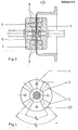
- the permanent magnets 3 are each spaced apart on the coupling parts 1, 2 with the formation of gaps 5.
- the pole pitch angle is marked with ⁇ p and the actual pole coverage with ⁇ M in FIG. 2.
- ⁇ M is smaller than ⁇ p .
- a can 6 can optionally be arranged as a partition between two work spaces.
- the permanent magnets 3 on the coupling parts 1 and 2 are again spaced apart from one another, forming gaps 5 in the circumferential direction, the actual pole coverage bed M again being smaller than the pole pitch angle ⁇ p .
Landscapes
- Engineering & Computer Science (AREA)
- Power Engineering (AREA)
- Dynamo-Electric Clutches, Dynamo-Electric Brakes (AREA)
Abstract
Description
- Die Erfindung betrifft eine Synchronkupplung, bestehend aus zwei mit Daüermagneten bestückten, im Abstand voneinander angeordneten, relativ zueinander drehbaren Teilen, von denen eines mit dem Antrieb und das andere mit dem Abtrieb verbunden ist.
- Synchronkupplungen werden in der Bauweise als Zentraldrehkupplung oder als Stirndrehkupplung ausgeführt. Bisher wurden permanent erregte Kupplungen in beiden Bauformen jeweils auf der ganzen Umfangsfläche durchgehend mit Dauermagnetmaterial bestückt, d.h., der Polteilungswinkel mit Dauermagnetmaterial war gleich der tatsächlichen Polbedeckung. Maximale Belegung der Kupplungsteile mit Dauermagnetmaterial ermöglicht die Übertragung des maximalen Drehmoments der Magnetkupplung. Hierbei ist aber der Einsatz von Dauermagnetmaterial nicht optimal. Durch Streuflüsse im Randbereich der Dauermagnete kommt es zu Verlusten von magnetischem Fluß.
- Aufgabe der vorliegenden Erfindung ist nun die Schaffung einer magnetischen Synchronkupplung mit optimalem Einsatz an Dauermagnetmaterial. Insbesondere bei Einsatz von hochwertigem teuren Dauermagnetmaterial ist dessen optimale Ausnutzung bei vorgegebenem zu übertragenen Drehmoment von besonderer wirtschaftlicher Bedeutung.
- Zur Lösung der gestellten Aufgabe wird eine Synchronkupplung der eingangs genannten'Art mit den in den Ansprüchen gekennzeichneten Merkmalen vorgeschlagen.
- Wie sich durch Untersuchungen gezeigt hat, ergibt sich ein minimaler Einsatz von Dauermagnetvolumen, bezogen auf das maximal zu übertragende Drehmoment dann, wenn keine kontinuierliche Dauermagnetbelegung der Kupplungsteile längs ihres Umfangs vorgenommen wird, sondern die tatsächliche Bedeckung der Teile mit Dauermagnetmaterial kleiner gewählt wird als der Polteilungswinkel. Neben der Verminderung der durch Streufelder entstehenden Verluste können auch die Wirbelstromverluste vermindert werden, die bei Anwesenheit von Zwischenwänden aus elektrisch leitfähigem Material zwischen den Kupplungsteilen entstehen.
- In der Zeichnung sind zwei Ausführungsbeispiele von Synchronkupplungen mit dem erfindungsgemäßen Merkmal dargestellt.
-
- Fig. 1 zeigt im Längsschnitt und
- Fig. 2 im Querschnitt eine Zentraldrehkupplung und
- Fig. 3 im Längsschnitt und
- Fig. 4 im Querschnitt eine Stirndrehkupplung.
- Gleiche Teile sind in den Figuren mit denselben Bezugszeichen versehen.
- Bei der Zentraldrehkupplung gemäß Figuren 1 und 2 sind an den Kupplungsteilen 1, 2, die im Abstand voneinander relativ zueinander drehbar angeordnet sind, Dauermagnete 3 befestigt. Durch Pfeile 4 ist die Magnetisierungsrichtung der Dauermagnete 3 gekennzeichnet.
- Wie am besten aus Fig. 2 ersichtlich ist, stehen die Dauermagnete 3 jeweils auf den Kupplungsteilen 1, 2 unter Bildung von Zwischenräumen 5 auf Abstand zueinander. Der Polteilungswinkel ist mit ϕp und die tatsächliche Polbedeckung mit ϕM in Fig. 2 gekennzeichnet. Dabei ist ϕM jeweils kleiner als ϕp.
- Zwischen den Kupplungsteilen 1, 2 kann gegebenenfalls ein Spaltrohr 6 als Trennwand zweier Arbeitsräume angeordnet werden.
- Bei dem in Figuren 3 und 4 dargestellten Beispiel einer Stirndrehkupplung stehen die Dauermagnete 3 auf den Kupplungsteilen 1 bzw. 2 jeweils wieder unter Bildung von Zwischenräumen 5 in Umfangsrichtung im Abstand zueinander, wobei die tatsächliche Polbedeckung ϕM wiederum kleiner ist als der Polteilungswinkel ϕp.
Claims (3)
Applications Claiming Priority (2)
| Application Number | Priority Date | Filing Date | Title |
|---|---|---|---|
| DE19803018186 DE3018186A1 (de) | 1980-05-13 | 1980-05-13 | Synchronkupplung |
| DE3018186 | 1980-05-13 |
Publications (2)
| Publication Number | Publication Date |
|---|---|
| EP0039777A2 true EP0039777A2 (de) | 1981-11-18 |
| EP0039777A3 EP0039777A3 (de) | 1982-06-30 |
Family
ID=6102241
Family Applications (1)
| Application Number | Title | Priority Date | Filing Date |
|---|---|---|---|
| EP81102559A Withdrawn EP0039777A3 (de) | 1980-05-13 | 1981-04-04 | Synchronkupplung |
Country Status (2)
| Country | Link |
|---|---|
| EP (1) | EP0039777A3 (de) |
| DE (1) | DE3018186A1 (de) |
Cited By (5)
| Publication number | Priority date | Publication date | Assignee | Title |
|---|---|---|---|---|
| EP0476357A1 (de) * | 1990-09-14 | 1992-03-25 | KSB Aktiengesellschaft | Magnetkupplung |
| GB2406000A (en) * | 2003-08-27 | 2005-03-16 | Freepower Ltd | Magnetic coupling for a turbo generator arrangement |
| US7112904B2 (en) * | 2004-03-16 | 2006-09-26 | Maguneo Co., Ltd. | Magnetic rotation transmitting device, hermetic stirring unit, and electric furnace |
| AT515555B1 (de) * | 2014-05-15 | 2015-10-15 | Univ Wien Tech | Magnetkupplung |
| TWI514726B (zh) * | 2010-05-17 | 2015-12-21 | Hitachi Metals Ltd | A manufacturing method of a coupling device and a coupling device |
Family Cites Families (3)
| Publication number | Priority date | Publication date | Assignee | Title |
|---|---|---|---|---|
| DE1704295U (de) * | 1954-06-04 | 1955-08-04 | Siemens Ag | Magnetsystem zum ubertragen einer drehkraft. |
| US3027472A (en) * | 1958-04-11 | 1962-03-27 | Westinghouse Electric Corp | Magnetic coupling arrangement |
| FR1315940A (fr) * | 1961-12-15 | 1963-01-25 | Dispositif étanche d'accouplement de deux arbres |
-
1980
- 1980-05-13 DE DE19803018186 patent/DE3018186A1/de not_active Ceased
-
1981
- 1981-04-04 EP EP81102559A patent/EP0039777A3/de not_active Withdrawn
Cited By (9)
| Publication number | Priority date | Publication date | Assignee | Title |
|---|---|---|---|---|
| EP0476357A1 (de) * | 1990-09-14 | 1992-03-25 | KSB Aktiengesellschaft | Magnetkupplung |
| GB2406000A (en) * | 2003-08-27 | 2005-03-16 | Freepower Ltd | Magnetic coupling for a turbo generator arrangement |
| GB2406000B (en) * | 2003-08-27 | 2006-12-20 | Freepower Ltd | Working energy recovery system having rotary magnetic coupling |
| US7112904B2 (en) * | 2004-03-16 | 2006-09-26 | Maguneo Co., Ltd. | Magnetic rotation transmitting device, hermetic stirring unit, and electric furnace |
| TWI514726B (zh) * | 2010-05-17 | 2015-12-21 | Hitachi Metals Ltd | A manufacturing method of a coupling device and a coupling device |
| AT515555B1 (de) * | 2014-05-15 | 2015-10-15 | Univ Wien Tech | Magnetkupplung |
| AT515555A4 (de) * | 2014-05-15 | 2015-10-15 | Univ Wien Tech | Magnetkupplung |
| WO2015172173A2 (de) | 2014-05-15 | 2015-11-19 | Technische Universität Wien | Magnetkupplung |
| US10704553B2 (en) | 2014-05-15 | 2020-07-07 | Technische Universität Wien | Magnetic coupling |
Also Published As
| Publication number | Publication date |
|---|---|
| DE3018186A1 (de) | 1981-11-19 |
| EP0039777A3 (de) | 1982-06-30 |
Similar Documents
| Publication | Publication Date | Title |
|---|---|---|
| DE69809689T2 (de) | Elektromotor mit Permanentmagnetrotor | |
| DE69129687T2 (de) | Vorrichtung zur Erzeugung eines Magnetfeldes für die Bildgebung mittels magnetischer Resonanz | |
| DE2940212C2 (de) | Magnetische Aufspannvorrichtung | |
| DE3427677A1 (de) | Elektrische umlaufende maschine | |
| DE1941180A1 (de) | Gleichstrom-Dynamo | |
| DE4027782A1 (de) | Elektrizitaetsgenerator | |
| DE1214724B (de) | Kontaktloser elektrischer Impulsgenerator | |
| EP0043981A1 (de) | Dauermagneterregter Läufer für eine elektrische Maschine | |
| EP0039777A2 (de) | Synchronkupplung | |
| DE3905997C2 (de) | ||
| EP0486119A2 (de) | Elektrodynamischer Ultraschallwandler | |
| DE3329689A1 (de) | Elektromagnetischer durchflussmesser | |
| DE8012888U1 (de) | Synchronkupplung | |
| DE1763858C2 (de) | Elektrische Maschine | |
| DE202019103225U1 (de) | Drehmomentoptimierter mehrpoliger Rotor für einen Elektromotor | |
| EP0724160A2 (de) | Sensorring | |
| DE3026299C2 (de) | ||
| DE2112422C3 (de) | Kupplung für Spielzeug- und Modelleisenbahnfahrzeuge | |
| DE2603092A1 (de) | Elektromagnetischer tonabnehmer | |
| DE8235610U1 (de) | Magnetzentraldrehkupplung | |
| DE4136686A1 (de) | Kupplungsmuffe | |
| DE728477C (de) | Goniometer fuer Peilzwecke | |
| DE702404C (de) | Drahtlose Sendeeinrichtung zur Kennzeichnung schmaler Fahrsektoren | |
| DE1959789C3 (de) | Dauermagnetsystem | |
| DE1958546A1 (de) | Gleichstrommotor mit Halleffekt |
Legal Events
| Date | Code | Title | Description |
|---|---|---|---|
| PUAI | Public reference made under article 153(3) epc to a published international application that has entered the european phase |
Free format text: ORIGINAL CODE: 0009012 |
|
| AK | Designated contracting states |
Designated state(s): CH FR GB LI NL |
|
| PUAL | Search report despatched |
Free format text: ORIGINAL CODE: 0009013 |
|
| AK | Designated contracting states |
Designated state(s): CH FR GB LI NL |
|
| 17P | Request for examination filed |
Effective date: 19821231 |
|
| R17P | Request for examination filed (corrected) |
Effective date: 19821222 |
|
| STAA | Information on the status of an ep patent application or granted ep patent |
Free format text: STATUS: THE APPLICATION HAS BEEN WITHDRAWN |
|
| 18W | Application withdrawn |
Withdrawal date: 19840406 |
|
| RIN1 | Information on inventor provided before grant (corrected) |
Inventor name: HUEBNER, KLAUS-DIETER, DR.-ING. Inventor name: SOBOTTKA, GERT, DR.-ING. |