EP0039823A2 - Support de moteur pour sa suspension par rapport à la structure du véhicule - Google Patents
Support de moteur pour sa suspension par rapport à la structure du véhicule Download PDFInfo
- Publication number
- EP0039823A2 EP0039823A2 EP81103190A EP81103190A EP0039823A2 EP 0039823 A2 EP0039823 A2 EP 0039823A2 EP 81103190 A EP81103190 A EP 81103190A EP 81103190 A EP81103190 A EP 81103190A EP 0039823 A2 EP0039823 A2 EP 0039823A2
- Authority
- EP
- European Patent Office
- Prior art keywords
- bellows
- armature
- inertia mass
- engine
- vibration
- Prior art date
- Legal status (The legal status is an assumption and is not a legal conclusion. Google has not performed a legal analysis and makes no representation as to the accuracy of the status listed.)
- Granted
Links
Images


Classifications
-
- F—MECHANICAL ENGINEERING; LIGHTING; HEATING; WEAPONS; BLASTING
- F16—ENGINEERING ELEMENTS AND UNITS; GENERAL MEASURES FOR PRODUCING AND MAINTAINING EFFECTIVE FUNCTIONING OF MACHINES OR INSTALLATIONS; THERMAL INSULATION IN GENERAL
- F16F—SPRINGS; SHOCK-ABSORBERS; MEANS FOR DAMPING VIBRATION
- F16F13/00—Units comprising springs of the non-fluid type as well as vibration-dampers, shock-absorbers, or fluid springs
- F16F13/04—Units comprising springs of the non-fluid type as well as vibration-dampers, shock-absorbers, or fluid springs comprising both a plastics spring and a damper, e.g. a friction damper
- F16F13/06—Units comprising springs of the non-fluid type as well as vibration-dampers, shock-absorbers, or fluid springs comprising both a plastics spring and a damper, e.g. a friction damper the damper being a fluid damper, e.g. the plastics spring not forming a part of the wall of the fluid chamber of the damper
- F16F13/22—Units comprising springs of the non-fluid type as well as vibration-dampers, shock-absorbers, or fluid springs comprising both a plastics spring and a damper, e.g. a friction damper the damper being a fluid damper, e.g. the plastics spring not forming a part of the wall of the fluid chamber of the damper characterised by comprising also a dynamic damper
-
- F—MECHANICAL ENGINEERING; LIGHTING; HEATING; WEAPONS; BLASTING
- F16—ENGINEERING ELEMENTS AND UNITS; GENERAL MEASURES FOR PRODUCING AND MAINTAINING EFFECTIVE FUNCTIONING OF MACHINES OR INSTALLATIONS; THERMAL INSULATION IN GENERAL
- F16F—SPRINGS; SHOCK-ABSORBERS; MEANS FOR DAMPING VIBRATION
- F16F7/00—Vibration-dampers; Shock-absorbers
- F16F7/10—Vibration-dampers; Shock-absorbers using inertia effect
- F16F7/104—Vibration-dampers; Shock-absorbers using inertia effect the inertia member being resiliently mounted
- F16F7/112—Vibration-dampers; Shock-absorbers using inertia effect the inertia member being resiliently mounted on fluid springs
-
- F—MECHANICAL ENGINEERING; LIGHTING; HEATING; WEAPONS; BLASTING
- F16—ENGINEERING ELEMENTS AND UNITS; GENERAL MEASURES FOR PRODUCING AND MAINTAINING EFFECTIVE FUNCTIONING OF MACHINES OR INSTALLATIONS; THERMAL INSULATION IN GENERAL
- F16F—SPRINGS; SHOCK-ABSORBERS; MEANS FOR DAMPING VIBRATION
- F16F9/00—Springs, vibration-dampers, shock-absorbers, or similarly-constructed movement-dampers using a fluid or the equivalent as damping medium
- F16F9/02—Springs, vibration-dampers, shock-absorbers, or similarly-constructed movement-dampers using a fluid or the equivalent as damping medium using gas only or vacuum
- F16F9/04—Springs, vibration-dampers, shock-absorbers, or similarly-constructed movement-dampers using a fluid or the equivalent as damping medium using gas only or vacuum in a chamber with a flexible wall
-
- F—MECHANICAL ENGINEERING; LIGHTING; HEATING; WEAPONS; BLASTING
- F02—COMBUSTION ENGINES; HOT-GAS OR COMBUSTION-PRODUCT ENGINE PLANTS
- F02B—INTERNAL-COMBUSTION PISTON ENGINES; COMBUSTION ENGINES IN GENERAL
- F02B75/00—Other engines
- F02B75/02—Engines characterised by their cycles, e.g. six-stroke
- F02B2075/022—Engines characterised by their cycles, e.g. six-stroke having less than six strokes per cycle
- F02B2075/027—Engines characterised by their cycles, e.g. six-stroke having less than six strokes per cycle four
Definitions
- the present invention relates to an engine mounting for suspending an engine relative to a vehicle structure.
- the elastic block structures employed for the suspension of an engine relative to the vehicle structure have a principal function to restrain low frequency vibrations falling within a vibration restrained domain.
- the block structures must have a high dynamic spring constant (high stiffness) suitable for restraining such vibrations.
- high stiffness suitable for restraining such low frequency vibrations results in a considerable impairement of the comfort under the effect of high frequency vibrations having frequencies falling within a vibration insulated domain.
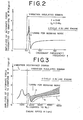
- the conventional elastic block structures are set to exibit a characteristic as represented by a broken line curve a shown in Fig. 3.
- the dynamic spring constant of the elastic blocks is set high enough to restrain or attenuate low frequency vibrations (between 5 and 30 Hz) produced by the uneveness of a road surface of the road or coming from the engine upon its idling operation, the high frequency vibrations (above 30 Hz) due to engine operation above the idle speed are not insulated or filtered satisfactorily.
- the dynamic spring constant is set high enough to insulate or filter the high frequency vibrations having frequencies above 30 Hz, the low frequency vibrations are not restrained or attenuated satisfactorily. Therefore, the elastic block structures cannot meet the both requirements, that is, restraining the low frequency vibrations within the vibration restrained domain and insulating the high frequency vibrations within the vibration insulated domain.
- an engine mounting for suspending an engine relative to a vehicle structure which comprises: a first armature for connection to the engine and a second armature for connection to a vehicle structure and a bellows interposed between the two armatures and defining therewith a closed enclosure, the closed enclosure being filled with pressurized gas, and an inertia mass mounted on the bellows.
- the mass of the inertia mass and the apparent spring constant of the bellows are selected such that the inertia mass vibrates in inverse phase relationship with the phase of vibration of the first armature when the engine is in operation within a vibration insulated domain.
- the engine mounting according to the present invention provides a sufficiently high spring constant under the effect of low frequency vibrations falling within a vibration retained domain because the inertia mass vibrates in the same phase relationship with the phase of vibrations of the first armature.
- the dynamic spring constant of the bellows can be increased by mounting partition wall means defining an orifice within the bellows.
- the partition wall means divides the closed enclosure into a first chamber and a second chamber.
- the dynamic spring constant of the bellows is increased by increasing the thickness of each of hinges of the bellows between the first armature and the inertia mass and between the second armature and the inertia mass, respectively.
- the thickened hinges consititute stops which are compressed under the effect of low freqeuncy vibrations falling within the vibration restrained domain, providing resistance to compression of the bellows, thus providing a high dynamic spring constant.
- the stops are left uncompressed under the effect of high frequency vibrations falling within the vibration insulated domain, thus providing the bellows with a low dynamic spring constant.
- an engine mounting according to the present invention is generally denoted by the reference numeral 10 which generally comprises an elastic bellows 12 interposed between a first or upper armature 14 for connection to an engine, a second or lower armature 16 for connection to a vehicle structure, that is, a vehicle body in this embodiment.
- the elastic bellows has an upper end clamped between the armature 14 and a retainer plate 18 which is pressed against the armature 14 by a stud bolt 20 threadedly engaged with the armature 14 to extend.therethrough.
- the lower end of the bellows 12 is clamped between the armature 16 and a retainer plate 22 which is pressed against the armature 16 by .a stud bolt 24 threadedly engaged with the armature 16. Therefore, the bellows 12 interposed between the two armatures 14 and 16 defines therewith a closed enclosure.
- the bellows has a waist portion 26 between an upper radially extending hinge 28 and a lower radially extending hinge 30.
- the stud bolt 20 is formed with an air supply passage 32 through which air is fed into the interior of the bellows 12 under pressure, so that the bellows 12 acts as an air spring.
- the inertia mass 12 has a ring portion 36 having a radially inwardly extending portion 38 fitted around the waist portion 26 in a manner to be clamped between the opposing wall portions 40 and 42 of the bellows 12 so that the mass of the inertia mass 34 is imparted to the waist portion 26 of the bellows 12.
- Air pressure within the bellows 12 and the mass of the inertia mass 34 are appripriately chosen such that in respect of vibrations within a vibration insulated domain coming from the engine upon its operation above an idle speed, the phase of vibrations of the inertia mass 34 is in inverse relationship with the phase of vibrations of the armature 14 connected"to the engine.
- an annular stop rubber 44 is attached to the peripheral portion of the armature 14 and a similar annular stop rubber 46 is attached to the outer peripheral portion 46 of the armature 16.
- k 2 apparent spring constant of bellows 12 retaining inertia mass 34, the apparent spring constant being determined by flexibility of bellows 12 and the internal pressure within the bellows 12 acting through effective pressure acting area to the inertia mass 34 : (natural angular frequency of the inertia mass 34 or the resonant frequency)
- w angular frequency of vibration imparted to armature 14
- the alternate force F transmitted to the armature 16 can be expressed as follows: The amplitude of the alternate force F transmitted to the armature 16 is therefore expressed as: The amplitude of the alternate force F transmitted to the armature 16 connected to the vehicle structure is plotted in Fig. 2 when the engine operates within the vibration insulated domain.
- the natural angular frequency (or resonant frequency) w of the inertia mass 34 that is determined by the mass m of the inertia mass 34 and the apparent spring constant k 2 of the bellows 12 is adjusted to correspond to the minimum engine speed of the vibration insulated domain, that is, 1,000 rpm (No) in this embodiment, so that within the vibration insulated domain, the inertia mass 34 can vibrate in inverse phase relationship with the phase of vibration of the armature 14 connected to the engine.
- the effective pressure acting area through which the bellows 12 contacts with the armature 16 connected to the vehiucle structure varies alternately and in inverse phase relationship with the phase of a variation in the internal pressure within the bellows 12 which internal pressure alternately varies in the same phase relationship with the phase of vibration of the armature 14 connected to the engine.
- This causes an effective reduction in alternate force transmitted to the armature 16 connected to the vehicle structure as shown by solid curve b in Fig. 3.
- the inertia mass 34 vibrates in the same phase relationship with the phase of vibration of the armature 14.
- the stiffness of the engine mounting 10 appreciably increases thus restraining the vibrations.
- An engine mounting 10A shown in Fig. 4 differs from the foregoing structure only in the presence of a stop arrangement for limiting excessive displacement of an inertia mass 34 in radial directions whereby to limit movement of the inertia mass 34 in forward and rearward direction of the vehicle and in leftward and rightward direction.
- the armature 14 and the armature 16 have their peripheral edges curved toward each other to form short sleeves 14A and 16A which partially surround the ring section 36 of the inertia mass 34 and the annular stop rubbers 44 and 46 have portions 44A and 46A extending to cover the inside walls of the short sleeves 14A and 16A.
- the extending portions 14A and 16A abut the ring section 36 of the inertia mass 34 when the inertia mass moves excessively in one of the radial directions, thereby preventing such excessive displacement of the inertia mass 34 relative to the armature 16 connected to the vehicle structure.
- the inertia mass 34 vibrates with a phase which is in inverse phase relationship with the phase of the vibration of the armature 14 on which the vibration of the engine is directly imparted, the amplitude of alternate force F transmitted to the armature 16 connected to the vehicle structure is considerably decreased, resulting in a considerable reduction in the vehicle interior noise.
- the alternating force F transmitted to the armature 16 can be expressed as: where: C 2 ,is the damping coefficient at which the vibration of inertia mass 34 is damped owing to the orifice 56.
- the operation of the engine mounting 10B is substantially the same as that of the engine mounting 10A shown in Fig. 4.
- the inertia mass vibrates in the same phase relationship with the phase of vibrations of the armature 14 and since the dynamic spring constant of the engine mounting is increased owing to the damping effect of the orifice 56, the low frequency vibrations are effectively restrained.
- a high dynamic spring constant is provided during operation within the vibration restrained domain, while, during operation within the vibration insulated domain a low dynamic spring constant is provided, thus.resulting in a considerable reduction in vehicle interior noise.
- the engine mounting 10C shown in Fig. 6 differs from the embodiment shown in Fig. 4 only in the provision of stops 58 and 60, each of which is constituted by increasing the thickness of .the wall of one of an upper hinge 28 and a lower hinge 30 of the bellows 12, so as to provide a high dynamic spring constant of the bellows 12 under the low frequency vibrations falling within the vibration restrained domain because the stops 58 and 60 are compressed to provide resistance to compressive movement of the engine mounting; and so as to provide a low dynamic spring constant under the high frequency vibrations falling within the vibration insulated domain because the stops 58 and 60 are left uncompressed under these vibrations.
- stops 58 and 60 each of which is constituted by increasing the thickness of .the wall of one of an upper hinge 28 and a lower hinge 30 of the bellows 12, so as to provide a high dynamic spring constant of the bellows 12 under the low frequency vibrations falling within the vibration restrained domain because the stops 58 and 60 are compressed to provide resistance to compressive movement of the engine mounting; and so as to provide
- the inertia mass 34 vibrates in the same phase relationship with the phase of vibration of the armature 14 and the stops 58 and 60 are compressed to provide a resistance to compression of the bellows 12, thus providing a sufficiently high dynamic spring constant to restarain the low frequency vibrations, while, under high frequency vibrations falling within vibration insulated domain, the inertia mass 34 vibrates in inverse phase relationship with the phase of the armature 14 connected to the engine and the stops 58 and 60 are left uncompressed not to provide any resistance to compression of the bellows 12, thus providing a sufficiently small low dynamic spring constant, thus effectively insulating the vibrations, with the consequent result that the vehicle interior noise is greately reduced.
Landscapes
- Engineering & Computer Science (AREA)
- General Engineering & Computer Science (AREA)
- Mechanical Engineering (AREA)
- Arrangement Or Mounting Of Propulsion Units For Vehicles (AREA)
- Combined Devices Of Dampers And Springs (AREA)
Applications Claiming Priority (6)
| Application Number | Priority Date | Filing Date | Title |
|---|---|---|---|
| JP6138380A JPS56157626A (en) | 1980-05-09 | 1980-05-09 | Engine mount for automobile |
| JP61383/80 | 1980-05-09 | ||
| JP64318/80 | 1980-05-15 | ||
| JP6431980A JPS56160218A (en) | 1980-05-15 | 1980-05-15 | Engine mount for automobile |
| JP6431880A JPS56160217A (en) | 1980-05-15 | 1980-05-15 | Engine mount for automobile |
| JP64319/80 | 1980-05-15 |
Publications (3)
| Publication Number | Publication Date |
|---|---|
| EP0039823A2 true EP0039823A2 (fr) | 1981-11-18 |
| EP0039823A3 EP0039823A3 (en) | 1982-03-31 |
| EP0039823B1 EP0039823B1 (fr) | 1984-11-28 |
Family
ID=27297484
Family Applications (1)
| Application Number | Title | Priority Date | Filing Date |
|---|---|---|---|
| EP81103190A Expired EP0039823B1 (fr) | 1980-05-09 | 1981-04-28 | Support de moteur pour sa suspension par rapport à la structure du véhicule |
Country Status (3)
| Country | Link |
|---|---|
| US (1) | US4424961A (fr) |
| EP (1) | EP0039823B1 (fr) |
| DE (1) | DE3167400D1 (fr) |
Cited By (5)
| Publication number | Priority date | Publication date | Assignee | Title |
|---|---|---|---|---|
| US4403762A (en) * | 1981-02-20 | 1983-09-13 | General Motors Corporation | Low force transmissibility mount |
| US4491304A (en) * | 1981-04-15 | 1985-01-01 | Nissan Motor Company, Limited | Fluid-filled engine mount device |
| EP0163949A3 (en) * | 1984-06-07 | 1987-08-26 | Audi Ag | Support, particularly for mounting a combustion engine in a motor vehicle |
| WO1993008414A1 (fr) * | 1991-10-17 | 1993-04-29 | Forsheda Ab | Amortisseur de vibrations |
| EP1048876A3 (fr) * | 1999-04-29 | 2001-02-07 | Draftex Industries Limited | Amortisseur réglable |
Families Citing this family (27)
| Publication number | Priority date | Publication date | Assignee | Title |
|---|---|---|---|---|
| US4560136A (en) * | 1982-01-11 | 1985-12-24 | Basore William T | Support for hi-fi turntable base |
| US4492143A (en) * | 1983-05-31 | 1985-01-08 | Westinghouse Electric Corp. | Anti-rotation mass support system particularly for missile support |
| JPS608540A (ja) * | 1983-06-27 | 1985-01-17 | Nissan Motor Co Ltd | 防振装置 |
| US4540331A (en) * | 1983-08-18 | 1985-09-10 | General Motors Corporation | Cut out device |
| DE3417927A1 (de) * | 1984-05-15 | 1985-11-21 | Continental Gummi-Werke Ag, 3000 Hannover | Elastisches lager fuer motoren, maschinenaggregate u.dgl. |
| DE3436822C2 (de) * | 1984-10-06 | 1986-10-23 | Adam Opel AG, 6090 Rüsselsheim | Lageranordnung, insbesondere zur Lagerung eines Motors am Fahrwerk eines Kraftfahrzeuges |
| US4744539A (en) * | 1987-01-21 | 1988-05-17 | Mack Trucks, Inc. | Vehicle mounting arrangement |
| US4860864A (en) * | 1987-11-16 | 1989-08-29 | General Motors Corporation | Clutch for robot or like |
| US4842118A (en) * | 1988-02-19 | 1989-06-27 | General Motors Corporation | Clutch |
| US4895115A (en) * | 1988-02-19 | 1990-01-23 | Volkswagen Ag | Mount with insulation for solid-conducted sound, in particular for an internal combustion engine |
| DE3841194A1 (de) * | 1988-12-07 | 1990-06-13 | Boge Ag | Elastisches gummilager |
| DE3841193A1 (de) * | 1988-12-07 | 1990-06-21 | Boge Ag | Hydraulisch daempfendes gummilager |
| JPH04219542A (ja) * | 1990-10-11 | 1992-08-10 | Bridgestone Corp | 防振装置 |
| DE4120841C1 (fr) * | 1991-06-25 | 1992-11-05 | Fa. Carl Freudenberg, 6940 Weinheim, De | |
| CA2094208A1 (fr) * | 1992-04-28 | 1993-10-29 | Richard D. Hein | Supports elastomeres amortisseurs pre-emballes; procede de fabrication; methode d'installation |
| US5701969A (en) * | 1995-05-16 | 1997-12-30 | Paccar Inc. | Frame beaming reduction assembly |
| FR2735831B1 (fr) * | 1995-06-21 | 1997-08-22 | Hutchinson | Support elastique pour masse vibrante |
| US5802966A (en) * | 1996-08-05 | 1998-09-08 | The Minster Machine Company | Dual mount control system |
| US6293532B2 (en) | 1997-08-04 | 2001-09-25 | Lord Corporation | Fluid and elastomer apparatus |
| TW365944U (en) * | 1998-10-14 | 1999-08-01 | Gigga Corp | Improved structure for shock absorber of bicycle |
| US6220585B1 (en) | 1998-10-29 | 2001-04-24 | Timbren Industries Incorporated | Multi-stage compression spring |
| WO2002040888A1 (fr) * | 2000-11-15 | 2002-05-23 | Bfs Diversified Products, Llc. | Ressort pneumatique anti-vibration |
| US6695294B2 (en) | 2001-07-20 | 2004-02-24 | Lord Corporation | Controlled equilibrium device with displacement dependent spring rates and integral damping |
| FR2829208B1 (fr) * | 2001-09-05 | 2003-12-05 | Hutchinson | Ensemble anti-vibratoire et support anti-vibratoire faisant partie de cet ensemble |
| US8328237B2 (en) * | 2007-10-04 | 2012-12-11 | Chrysler Group Llc | Steering column dynamic damper |
| JP6697568B2 (ja) | 2016-03-03 | 2020-05-20 | エーエスエムエル ネザーランズ ビー.ブイ. | 振動絶縁装置、リソグラフィ装置、およびデバイス製造方法 |
| CN109026606A (zh) * | 2018-09-10 | 2018-12-18 | 青岛万宝压缩机有限公司 | 阻尼动力吸振器及压缩机 |
Family Cites Families (19)
| Publication number | Priority date | Publication date | Assignee | Title |
|---|---|---|---|---|
| CA723039A (en) | 1965-12-07 | Societe Luxembourgeoise De Brevets Et De Participations | Resilient connecting devices | |
| DE446516C (de) | 1925-07-22 | 1927-07-07 | Ettore Caretta | Stossdaempfer mit zwei miteinander in Verbindung stehenden Kammern |
| FR809065A (fr) * | 1935-11-13 | 1937-02-23 | Dispositif de liaison servant d'amortisseur de vibrations et de chocs | |
| US2115072A (en) | 1937-01-25 | 1938-04-26 | Gen Motors Corp | Pneumatic suspension device |
| US2149863A (en) * | 1937-07-06 | 1939-03-07 | Gen Motors Corp | Harmonic balancer for vehicle road wheels |
| US2562195A (en) | 1945-07-07 | 1951-07-31 | Norman E Lee | Mounting |
| US2773686A (en) | 1947-09-17 | 1956-12-11 | Gen Motors Corp | Air spring |
| US2683016A (en) | 1951-12-26 | 1954-07-06 | Lord Mfg Co | Mounting |
| NL107590C (fr) * | 1953-04-25 | |||
| DE1072018B (fr) * | 1955-04-15 | |||
| US3137466A (en) * | 1962-05-23 | 1964-06-16 | Gen Motors Corp | Engine mount |
| DE1264878B (de) * | 1964-02-18 | 1968-03-28 | Gomma Antivibranti Applic | Balgluftfeder |
| US3368807A (en) | 1966-01-19 | 1968-02-13 | Litton Systems Inc | Vibration isolator |
| SU769144A1 (ru) | 1978-03-01 | 1980-10-07 | Горьковский государственный университет им.Н.И.Лобачевского | Пневматический упругий элемент |
| EP0006819B1 (fr) * | 1978-07-03 | 1984-06-27 | Automobiles Peugeot | Dispositif de suspension, notamment de moteur d'un véhicule automobile |
| FR2435632A1 (fr) * | 1978-09-06 | 1980-04-04 | Hutchinson Mapa | Perfectionnements apportes aux supports elastiques, notamment pour suspensions de moteurs de vehicules |
| FR2435623A1 (fr) | 1978-09-11 | 1980-04-04 | Renault | Agrafe |
| EP0015378B1 (fr) * | 1979-03-01 | 1984-04-25 | Messerschmitt-Bölkow-Blohm Gesellschaft mit beschränkter Haftung | Isolateur de vibrations |
| DE2947018C2 (de) * | 1979-11-22 | 1982-05-27 | Audi Nsu Auto Union Ag, 7107 Neckarsulm | Elastisches Lager, insbesondere zur Lagerung einer Brennkraftmaschine in einem Kraftfahrzeug |
-
1981
- 1981-04-28 EP EP81103190A patent/EP0039823B1/fr not_active Expired
- 1981-04-28 DE DE8181103190T patent/DE3167400D1/de not_active Expired
- 1981-05-07 US US06/261,374 patent/US4424961A/en not_active Expired - Fee Related
Cited By (5)
| Publication number | Priority date | Publication date | Assignee | Title |
|---|---|---|---|---|
| US4403762A (en) * | 1981-02-20 | 1983-09-13 | General Motors Corporation | Low force transmissibility mount |
| US4491304A (en) * | 1981-04-15 | 1985-01-01 | Nissan Motor Company, Limited | Fluid-filled engine mount device |
| EP0163949A3 (en) * | 1984-06-07 | 1987-08-26 | Audi Ag | Support, particularly for mounting a combustion engine in a motor vehicle |
| WO1993008414A1 (fr) * | 1991-10-17 | 1993-04-29 | Forsheda Ab | Amortisseur de vibrations |
| EP1048876A3 (fr) * | 1999-04-29 | 2001-02-07 | Draftex Industries Limited | Amortisseur réglable |
Also Published As
| Publication number | Publication date |
|---|---|
| EP0039823B1 (fr) | 1984-11-28 |
| DE3167400D1 (en) | 1985-01-10 |
| EP0039823A3 (en) | 1982-03-31 |
| US4424961A (en) | 1984-01-10 |
Similar Documents
| Publication | Publication Date | Title |
|---|---|---|
| US4424961A (en) | Engine mounting for suspending engine relative to vehicle structure | |
| US4428569A (en) | Engine mounting for automobile | |
| US4895353A (en) | Fluid filled elastomeric damping device | |
| EP0809040B1 (fr) | Support élastique fluidique avec passages d'ouverture règlés pour amortir vibrations d'entrée dans de séries respectives differentes de fréquence | |
| US6176477B1 (en) | Liquid-sealing type variation isolating apparatus | |
| US5044813A (en) | Bush type hydraulically damped engine or transmission mount | |
| US5188346A (en) | Fluid-filled elastic mount having two pressure-receiving chambers communicating with equilibrium chamber through respective orifice passages | |
| GB2154699A (en) | Vibration damper | |
| GB2158182A (en) | A hydraulically damped rubber mounting | |
| JPH11315881A (ja) | 油圧緩衝式軸受 | |
| US4826126A (en) | Fluid-filled elastic mounting structure | |
| US4971300A (en) | Motor mount having improved hydraulic damping | |
| JPH0330736B2 (fr) | ||
| EP0823568A3 (fr) | Dispositif isolateur anti-vibrations renfermant un liquide | |
| US4941649A (en) | Fluid-filled cylindrical elastic mount having means for improved durability of elastic body | |
| US5029825A (en) | Fluid filled engine mount | |
| US20050285318A1 (en) | Hydro-mount | |
| US4664360A (en) | Engine mount | |
| JPH06193670A (ja) | 流体封入式防振装置 | |
| JP3570105B2 (ja) | 液体封入式防振装置 | |
| KR100243617B1 (ko) | 액체봉입식 엔진마운트 | |
| KR100246665B1 (ko) | 감쇠력이 조절가능한 유체봉입식 엔진마운트 | |
| JPS62127538A (ja) | 振動体支持装置 | |
| KR100192480B1 (ko) | 자동차의 유체봉입식 엔진마운트 | |
| JP3519101B2 (ja) | 液体封入式防振装置 |
Legal Events
| Date | Code | Title | Description |
|---|---|---|---|
| PUAI | Public reference made under article 153(3) epc to a published international application that has entered the european phase |
Free format text: ORIGINAL CODE: 0009012 |
|
| AK | Designated contracting states |
Designated state(s): DE FR GB |
|
| PUAL | Search report despatched |
Free format text: ORIGINAL CODE: 0009013 |
|
| AK | Designated contracting states |
Designated state(s): DE FR GB |
|
| 17P | Request for examination filed |
Effective date: 19820420 |
|
| GRAA | (expected) grant |
Free format text: ORIGINAL CODE: 0009210 |
|
| AK | Designated contracting states |
Designated state(s): DE FR GB |
|
| REF | Corresponds to: |
Ref document number: 3167400 Country of ref document: DE Date of ref document: 19850110 |
|
| ET | Fr: translation filed | ||
| RAP2 | Party data changed (patent owner data changed or rights of a patent transferred) |
Owner name: NISSAN MOTOR CO., LTD. |
|
| PLBE | No opposition filed within time limit |
Free format text: ORIGINAL CODE: 0009261 |
|
| STAA | Information on the status of an ep patent application or granted ep patent |
Free format text: STATUS: NO OPPOSITION FILED WITHIN TIME LIMIT |
|
| 26N | No opposition filed | ||
| PG25 | Lapsed in a contracting state [announced via postgrant information from national office to epo] |
Ref country code: FR Free format text: LAPSE BECAUSE OF NON-PAYMENT OF DUE FEES Effective date: 19871230 |
|
| GBPC | Gb: european patent ceased through non-payment of renewal fee | ||
| PG25 | Lapsed in a contracting state [announced via postgrant information from national office to epo] |
Ref country code: DE Effective date: 19880101 |
|
| REG | Reference to a national code |
Ref country code: FR Ref legal event code: ST |
|
| PG25 | Lapsed in a contracting state [announced via postgrant information from national office to epo] |
Ref country code: GB Effective date: 19881118 |