EP0039904A2 - Mélangeur de purin actionné par la prise de force - Google Patents
Mélangeur de purin actionné par la prise de force Download PDFInfo
- Publication number
- EP0039904A2 EP0039904A2 EP81103451A EP81103451A EP0039904A2 EP 0039904 A2 EP0039904 A2 EP 0039904A2 EP 81103451 A EP81103451 A EP 81103451A EP 81103451 A EP81103451 A EP 81103451A EP 0039904 A2 EP0039904 A2 EP 0039904A2
- Authority
- EP
- European Patent Office
- Prior art keywords
- tractor
- mixer according
- pivoting arm
- arm
- mixer
- Prior art date
- Legal status (The legal status is an assumption and is not a legal conclusion. Google has not performed a legal analysis and makes no representation as to the accuracy of the status listed.)
- Granted
Links
Images


Classifications
-
- A—HUMAN NECESSITIES
- A01—AGRICULTURE; FORESTRY; ANIMAL HUSBANDRY; HUNTING; TRAPPING; FISHING
- A01C—PLANTING; SOWING; FERTILISING
- A01C3/00—Treating manure; Manuring
- A01C3/02—Storage places for manure, e.g. cisterns for liquid manure; Installations for fermenting manure
- A01C3/026—Storage places for manure, e.g. cisterns for liquid manure; Installations for fermenting manure with mixing or agitating devices
-
- B—PERFORMING OPERATIONS; TRANSPORTING
- B01—PHYSICAL OR CHEMICAL PROCESSES OR APPARATUS IN GENERAL
- B01F—MIXING, e.g. DISSOLVING, EMULSIFYING OR DISPERSING
- B01F33/00—Other mixers; Mixing plants; Combinations of mixers
- B01F33/50—Movable or transportable mixing devices or plants
- B01F33/502—Vehicle-mounted mixing devices
-
- B—PERFORMING OPERATIONS; TRANSPORTING
- B01—PHYSICAL OR CHEMICAL PROCESSES OR APPARATUS IN GENERAL
- B01F—MIXING, e.g. DISSOLVING, EMULSIFYING OR DISPERSING
- B01F2101/00—Mixing characterised by the nature of the mixed materials or by the application field
- B01F2101/005—Mixing or agitating manure, dung
-
- B—PERFORMING OPERATIONS; TRANSPORTING
- B01—PHYSICAL OR CHEMICAL PROCESSES OR APPARATUS IN GENERAL
- B01F—MIXING, e.g. DISSOLVING, EMULSIFYING OR DISPERSING
- B01F27/00—Mixers with rotary stirring devices in fixed receptacles; Kneaders
Definitions
- the invention relates to a slurry mixer for driving by means of the power take-off of a tractor with a mounting frame that can be connected to the three-point linkage system of the tractor and a pivoting pivoting arm, at the end of which is directed away from the tractor, a tubular mixer housing between an approximately horizontal transport position and an approximately vertical one Insert position is pivotally mounted.
- Manure mixers of this type should also be able to be introduced through very small pit openings.
- the swivel arm must also be able to be inserted into the pit opening. This presupposes that it can also be tilted downwards in every lower link position, especially when the lower links are raised.
- the invention has for its object to propose a slurry mixer that can be easily introduced by the tractor driver without having to dismount and without risk of accident in every small pit opening.
- the pivoting arm can be coupled to the lower links by means of a stop.
- the pivoting arm can be in a stretched or slightly upward position with respect to the lower links by means of the lower links raise and lower as if it were rigidly connected to them.
- the stop is preferably designed as a pivotable support flap or self-engaging pawl. It is also expedient to graduate the stop, for example to provide it with sawtooth-like incisions, so that the pivoting arm can assume different angular positions with respect to the lower links. Such a slurry mixer is therefore suitable for tractors of very different types and tires.
- the three-point handlebar systems of heavy tractors are usually designed for much heavier attachments or combinations of devices than manure mixers, e.g. B. for 10-pair plows. It is therefore extremely easy to damage the manure mixer by a little carelessness in the operation during the introduction or removal process. It is therefore proposed that the mutual mobility of at least two of the parts of the slurry mixer be limited by means of a separable, deformable or displaceable element while overcoming a frictional engagement while maintaining an emergency travel path is. This is to be understood as a break or overload protection in such a way that the break, the deformation or displacement of the relevant security element gives a small additional freedom of movement, which is measured jerkily. This makes the tractor driver aware, but the work process does not have to be interrupted.
- This proposal can be realized, for example, in connection with a support flap made of two identical support pawls in such a way that the two support pawls are connected to one another by a crossbar that crosses the lower link extensions and can be saddled on them, and that the axle journals used for the support pawls can be sheared off in the event of an overload.
- this crossbar abuts the lower link extensions. The driver realizes that he has done something wrong. Then he then exchanged the sheared journal for new ones.
- this two-part actuator is fully bent. It does not work and does not interfere. However, if the swivel arm tilts downwards, the actuator stretches and holds the freely projecting swivel arm in a certain inclination position that can be changed by turning the spindle.
- a non-rigid traction element for example a rope
- the spindle drive could also connect a non-rigid traction element, for example a rope
- FIG. 1 shows the following structural details.
- An agricultural tractor the rear tire 1 of which is indicated by dash-dotted lines, has two lower links 3 which can be pivoted about an axis 2.
- a triangular mounting frame 5 is articulated by means of two lower link pins 4, the upper part of which is articulated by means of an upper link 6 to a fixed connection point 7 on the tractor.
- a swivel arm 8 consisting of a bracket and two parallel bars is also mounted.
- the spars receive in a known manner a mixer tube 9 (FIG. 5) which is pivotably mounted at half the length with the help of cross pins 10 at the end of the spar.
- a propeller shaft is mounted in the mixer tube 9, which has at least one propeller 11 at one end and one from the other end a sleeve having 12 surrounded elenkwellenanschluß G, which can be connected via an articulated shaft to the PTO shaft of the tractor.
- Each lower link 3 is extended by means of an extension rail 13 beyond the lower link pins 4 to the rear.
- the extension rails have upstanding bearing eyes 14 which are inserted between the lower links 3 and the legs of the mounting frame 5 on the lower link pins 4.
- two support pawls 17 are mounted by means of two commercially available screws 18, which are specially dimensioned so that they are sheared off when overloaded.
- the support pawls are connected to one another by means of a cross-sectionally angular crossmember 19 which extends transversely over the extension rails 13.
- the support pawls 17 have two right-angled incisions 20, into which a transverse edge 21 of the bracket part of the pivoting arm 8 is able to insert.
- the support flap consisting of the support pawls 17 and the cross member 19 can be actuated from the driver's seat of the tractor.
- a spindle drive 24 which is articulated with two brackets 23 is provided as an actuator for the mixing depth.
- This consists of a fork-shaped nut piece, a spindle 25, which is mounted in a pivotable axial bearing at the upper end of the mounting frame 5 and a hand crank 26.
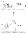
- FIG. 5 shows the transport position, which is also shown in FIG. 2.
- the swivel arm 8 lies in the lower of the two incisions 20 of the support pawls 17, the lower links forming only an angle of approximately 5 ° with the swivel arm 8.
- the mixer tube 9 is pivoted into a horizontal position in which it can also be fixed on the pivoting arm 8.
- the actuator consisting of the spindle drive 24 and the tabs 23, is strongly angled and out of function.
- the driver now lifts the lower links 3 to the upper end position with the aid of the tractor hydraulics, which, incidentally, are not shown in detail.
- the pivoting arm 8 is now so steep that the mixer tube 9 can be pivoted into an almost vertical position, the so-called insertion position.
- both parts are connected by means of a rope piece 29 so that the mixer tube is slightly inclined and thus stable.
- the pivoting arm 8 now pushes through the pit opening 28 due to its greater inclination, whereby it slides on the upper edge of the pit opening.
- the mixer tube 9 grazes the lower edge of the pit opening on the opposite side and is thus guided automatically and adjusted in the direction of the pivoting arm 8.
- the point finally comes where, as also shown in FIG. 3, the actuator 23, 24 engages.
- the protrusion of the tabs 23 comes to rest on the shear pins 27.
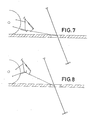
- the inclination of the pivoting arm 8 is fixed and, as shown in FIG. 9, it can freely cantilever without contacting the edge of the pit. If you now turn the crank handle 26, the inclination changes.
- the propeller 11 can be steplessly and sensitively adjusted to the correct depth at the given liquid manure fill level and to the most favorable flow pattern.
Landscapes
- Life Sciences & Earth Sciences (AREA)
- Soil Sciences (AREA)
- Environmental Sciences (AREA)
- Chemical & Material Sciences (AREA)
- Chemical Kinetics & Catalysis (AREA)
- Mixers Of The Rotary Stirring Type (AREA)
- Treatment Of Sludge (AREA)
- Accessories For Mixers (AREA)
- Agricultural Machines (AREA)
- Soil Working Implements (AREA)
Priority Applications (1)
| Application Number | Priority Date | Filing Date | Title |
|---|---|---|---|
| AT81103451T ATE9532T1 (de) | 1980-05-13 | 1981-05-07 | Guellemixer mit zapfwellenantrieb. |
Applications Claiming Priority (2)
| Application Number | Priority Date | Filing Date | Title |
|---|---|---|---|
| DE3018264 | 1980-05-13 | ||
| DE3018264A DE3018264A1 (de) | 1980-05-13 | 1980-05-13 | Guellemixer mit zapfwellenantrieb |
Publications (3)
| Publication Number | Publication Date |
|---|---|
| EP0039904A2 true EP0039904A2 (fr) | 1981-11-18 |
| EP0039904A3 EP0039904A3 (en) | 1982-07-14 |
| EP0039904B1 EP0039904B1 (fr) | 1984-09-26 |
Family
ID=6102293
Family Applications (1)
| Application Number | Title | Priority Date | Filing Date |
|---|---|---|---|
| EP81103451A Expired EP0039904B1 (fr) | 1980-05-13 | 1981-05-07 | Mélangeur de purin actionné par la prise de force |
Country Status (3)
| Country | Link |
|---|---|
| EP (1) | EP0039904B1 (fr) |
| AT (1) | ATE9532T1 (fr) |
| DE (2) | DE3018264A1 (fr) |
Cited By (1)
| Publication number | Priority date | Publication date | Assignee | Title |
|---|---|---|---|---|
| FR2560495A1 (fr) * | 1984-03-01 | 1985-09-06 | Lucas Sa G | Nouvel appareil d'extraction de lisier |
Families Citing this family (2)
| Publication number | Priority date | Publication date | Assignee | Title |
|---|---|---|---|---|
| DE3408453C2 (de) * | 1984-03-08 | 1986-06-12 | SUMA Sulzberger Maschinenbau GmbH & Co KG, Gerhard Thürwächter, 8961 Sulzberg | Aufhängeeinrichtung einer Güllerührwelle an einem Traktor |
| DE3432851C1 (de) * | 1984-09-07 | 1986-03-13 | Fa. Josef Brand, 4517 Hilter | Rührvorrichtung zur Aufbereitung von Gülle |
Family Cites Families (6)
| Publication number | Priority date | Publication date | Assignee | Title |
|---|---|---|---|---|
| CH411438A (de) * | 1963-02-21 | 1966-04-15 | Bauer Roehren Pumpen | Rührwerk für die Aufbereitung von Dünger bzw. Gülle |
| FR1533051A (fr) * | 1967-08-01 | 1968-07-12 | Dispositif de support pour l'installation de pompes transportables de circulation dans des fosses ou autres réservoirs enfouis dans le sol | |
| CA954738A (en) * | 1971-01-11 | 1974-09-17 | Massey-Ferguson Inc. | Overload release assembly |
| AT335214B (de) * | 1975-05-07 | 1977-02-25 | Weishaupl Walter | Ruhrmixer fur die aufbereitung von gulle |
| SE424947B (sv) * | 1978-02-21 | 1982-08-23 | Stiftelsen Ind Utvecklingscent | Fordonsburen berare for skogsbruksredskap |
| FR2453673A1 (fr) * | 1979-04-11 | 1980-11-07 | Bihan Rene | Appareil pour le malaxage, le hachage et l'homogeneisation d'eaux grasses, de lisiers ou de melanges contenant des particules solides |
-
1980
- 1980-05-13 DE DE3018264A patent/DE3018264A1/de not_active Withdrawn
-
1981
- 1981-05-07 DE DE8181103451T patent/DE3166272D1/de not_active Expired
- 1981-05-07 EP EP81103451A patent/EP0039904B1/fr not_active Expired
- 1981-05-07 AT AT81103451T patent/ATE9532T1/de not_active IP Right Cessation
Cited By (1)
| Publication number | Priority date | Publication date | Assignee | Title |
|---|---|---|---|---|
| FR2560495A1 (fr) * | 1984-03-01 | 1985-09-06 | Lucas Sa G | Nouvel appareil d'extraction de lisier |
Also Published As
| Publication number | Publication date |
|---|---|
| EP0039904B1 (fr) | 1984-09-26 |
| EP0039904A3 (en) | 1982-07-14 |
| DE3018264A1 (de) | 1981-11-19 |
| DE3166272D1 (de) | 1984-10-31 |
| ATE9532T1 (de) | 1984-10-15 |
Similar Documents
| Publication | Publication Date | Title |
|---|---|---|
| DE69513875T2 (de) | Mähmaschine mit einer Sicherheitsvorrichtung | |
| EP0452636B1 (fr) | Dispositif de suspension pour un dispositif monté sur un véhicule | |
| EP0096200A1 (fr) | Véhicule avec instrument de travail | |
| DE1247725B (de) | Schnellkupplung | |
| DE1245561B (de) | Hubwagen | |
| DE3926367A1 (de) | Vorrichtung fuer eine traktorkupplung zur begrenzung von schlenkerbewegungen | |
| DE69706332T2 (de) | Mähmaschine | |
| DE3628605A1 (de) | Heuwerbungsmaschine | |
| DE2733039C2 (fr) | ||
| EP2926643A1 (fr) | Machine agricole | |
| DE3129789C2 (fr) | ||
| EP0039904B1 (fr) | Mélangeur de purin actionné par la prise de force | |
| DE1222726B (de) | Kupplungsvorrichtung zwischen einem Schlepper und einem an diesen anzubauenden Arbeitsgeraet | |
| DE1430139A1 (de) | Kraftfahrzeug | |
| DE1430138C3 (de) | Steuereinrichtung für ein hydrostatisches Getriebe eines mit einer Anhängevorrichtung bzw. einem Geräteanschluß ausgerüsteten Schleppers | |
| DE2622444A1 (de) | Anbauvorrichtung fuer landwirtschaftliche verteilmaschinen | |
| DE1482095C3 (de) | Mähmaschine | |
| DE69012018T2 (de) | Öffnungs- und Verschlussvorrichtung für die Hintertür eines Anhängers. | |
| DE1582326A1 (de) | Maeher | |
| DE3328807C2 (fr) | ||
| DE3784328T2 (de) | Landmaschine. | |
| DE2165256A1 (de) | Einrichtung zum Einstellen des seitlichen Spiels oder Abstandes von Zugstangen an Ackerschleppern und dgl | |
| DE3448426C3 (de) | Landwirtschaftliche Maschine | |
| DE2160538C2 (de) | Anbauvorrichtung für eine an das Hubgestänge eines Schleppers anbaubare Heuwerbungsmaschine | |
| DE1657606C3 (de) | Mähvorrichtung |
Legal Events
| Date | Code | Title | Description |
|---|---|---|---|
| PUAI | Public reference made under article 153(3) epc to a published international application that has entered the european phase |
Free format text: ORIGINAL CODE: 0009012 |
|
| AK | Designated contracting states |
Designated state(s): AT BE CH DE LU NL |
|
| PUAL | Search report despatched |
Free format text: ORIGINAL CODE: 0009013 |
|
| AK | Designated contracting states |
Designated state(s): AT BE CH DE LU NL |
|
| 17P | Request for examination filed |
Effective date: 19820901 |
|
| GRAA | (expected) grant |
Free format text: ORIGINAL CODE: 0009210 |
|
| AK | Designated contracting states |
Designated state(s): AT BE CH DE LI LU NL |
|
| REF | Corresponds to: |
Ref document number: 9532 Country of ref document: AT Date of ref document: 19841015 Kind code of ref document: T |
|
| REF | Corresponds to: |
Ref document number: 3166272 Country of ref document: DE Date of ref document: 19841031 |
|
| PG25 | Lapsed in a contracting state [announced via postgrant information from national office to epo] |
Ref country code: LU Free format text: LAPSE BECAUSE OF NON-PAYMENT OF DUE FEES Effective date: 19850531 |
|
| PLBE | No opposition filed within time limit |
Free format text: ORIGINAL CODE: 0009261 |
|
| STAA | Information on the status of an ep patent application or granted ep patent |
Free format text: STATUS: NO OPPOSITION FILED WITHIN TIME LIMIT |
|
| 26N | No opposition filed | ||
| PGFP | Annual fee paid to national office [announced via postgrant information from national office to epo] |
Ref country code: NL Payment date: 19860531 Year of fee payment: 6 |
|
| PG25 | Lapsed in a contracting state [announced via postgrant information from national office to epo] |
Ref country code: LI Effective date: 19870531 Ref country code: CH Effective date: 19870531 |
|
| BERE | Be: lapsed |
Owner name: RECK ANTON Effective date: 19870531 |
|
| PG25 | Lapsed in a contracting state [announced via postgrant information from national office to epo] |
Ref country code: NL Effective date: 19871201 |
|
| NLV4 | Nl: lapsed or anulled due to non-payment of the annual fee | ||
| REG | Reference to a national code |
Ref country code: CH Ref legal event code: PL |
|
| PGFP | Annual fee paid to national office [announced via postgrant information from national office to epo] |
Ref country code: AT Payment date: 19890512 Year of fee payment: 9 |
|
| PG25 | Lapsed in a contracting state [announced via postgrant information from national office to epo] |
Ref country code: BE Effective date: 19890531 |
|
| PGFP | Annual fee paid to national office [announced via postgrant information from national office to epo] |
Ref country code: DE Payment date: 19890602 Year of fee payment: 9 |
|
| PG25 | Lapsed in a contracting state [announced via postgrant information from national office to epo] |
Ref country code: AT Effective date: 19900507 |
|
| PG25 | Lapsed in a contracting state [announced via postgrant information from national office to epo] |
Ref country code: DE Effective date: 19910201 |