EP0040004A1 - Ring-Laser-Gyroskop - Google Patents
Ring-Laser-Gyroskop Download PDFInfo
- Publication number
- EP0040004A1 EP0040004A1 EP81301685A EP81301685A EP0040004A1 EP 0040004 A1 EP0040004 A1 EP 0040004A1 EP 81301685 A EP81301685 A EP 81301685A EP 81301685 A EP81301685 A EP 81301685A EP 0040004 A1 EP0040004 A1 EP 0040004A1
- Authority
- EP
- European Patent Office
- Prior art keywords
- cavity
- cavities
- corners
- mirrors
- cube
- Prior art date
- Legal status (The legal status is an assumption and is not a legal conclusion. Google has not performed a legal analysis and makes no representation as to the accuracy of the status listed.)
- Granted
Links
- 240000004282 Grewia occidentalis Species 0.000 claims description 2
- 239000003989 dielectric material Substances 0.000 claims description 2
- 239000000463 material Substances 0.000 description 14
- 239000007789 gas Substances 0.000 description 7
- 238000005553 drilling Methods 0.000 description 6
- 238000002789 length control Methods 0.000 description 6
- 230000000694 effects Effects 0.000 description 4
- 238000003754 machining Methods 0.000 description 3
- 238000000926 separation method Methods 0.000 description 3
- 238000000034 method Methods 0.000 description 2
- 230000003287 optical effect Effects 0.000 description 2
- 239000006094 Zerodur Substances 0.000 description 1
- OTCHGXYCWNXDOA-UHFFFAOYSA-N [C].[Zr] Chemical compound [C].[Zr] OTCHGXYCWNXDOA-UHFFFAOYSA-N 0.000 description 1
- 230000003321 amplification Effects 0.000 description 1
- 238000010276 construction Methods 0.000 description 1
- 239000002241 glass-ceramic Substances 0.000 description 1
- 229910052734 helium Inorganic materials 0.000 description 1
- 239000001307 helium Substances 0.000 description 1
- SWQJXJOGLNCZEY-UHFFFAOYSA-N helium atom Chemical compound [He] SWQJXJOGLNCZEY-UHFFFAOYSA-N 0.000 description 1
- 230000007774 longterm Effects 0.000 description 1
- 239000000203 mixture Substances 0.000 description 1
- 229910052754 neon Inorganic materials 0.000 description 1
- GKAOGPIIYCISHV-UHFFFAOYSA-N neon atom Chemical compound [Ne] GKAOGPIIYCISHV-UHFFFAOYSA-N 0.000 description 1
- 238000003199 nucleic acid amplification method Methods 0.000 description 1
- 230000000644 propagated effect Effects 0.000 description 1
- 238000007789 sealing Methods 0.000 description 1
- 239000007787 solid Substances 0.000 description 1
Images
Classifications
-
- G—PHYSICS
- G01—MEASURING; TESTING
- G01C—MEASURING DISTANCES, LEVELS OR BEARINGS; SURVEYING; NAVIGATION; GYROSCOPIC INSTRUMENTS; PHOTOGRAMMETRY OR VIDEOGRAMMETRY
- G01C19/00—Gyroscopes; Turn-sensitive devices using vibrating masses; Turn-sensitive devices without moving masses; Measuring angular rate using gyroscopic effects
- G01C19/58—Turn-sensitive devices without moving masses
- G01C19/64—Gyrometers using the Sagnac effect, i.e. rotation-induced shifts between counter-rotating electromagnetic beams
- G01C19/66—Ring laser gyrometers
- G01C19/668—Assemblies for measuring along different axes, e.g. triads
-
- H—ELECTRICITY
- H01—ELECTRIC ELEMENTS
- H01S—DEVICES USING THE PROCESS OF LIGHT AMPLIFICATION BY STIMULATED EMISSION OF RADIATION [LASER] TO AMPLIFY OR GENERATE LIGHT; DEVICES USING STIMULATED EMISSION OF ELECTROMAGNETIC RADIATION IN WAVE RANGES OTHER THAN OPTICAL
- H01S3/00—Lasers, i.e. devices using stimulated emission of electromagnetic radiation in the infrared, visible or ultraviolet wave range
- H01S3/05—Construction or shape of optical resonators; Accommodation of active medium therein; Shape of active medium
- H01S3/08—Construction or shape of optical resonators or components thereof
- H01S3/081—Construction or shape of optical resonators or components thereof comprising three or more reflectors
- H01S3/083—Ring lasers
Definitions
- This invention relates to ring laser gyroscopes and more particularly to such gyroscopes having a plurality of sensitive axes.
- Ring laser gyroscopes have one or more sensitive axes and for each axis there is provided a gas-filled cavity or ring disposed in a plane at right angles to the associated axis, each cavity comprising three or more linear, and usually equal, limbs.
- Each cavity propagate two beams of light travelling in opposite directions and directed about a closed loop, by three or more mirrors located at the respective cavity corners, and regeneratively amplified at frequencies for which the path length equals an integral number of wavelengths. Amplification is achieved through a gas discharge within the cavity, at least one anode and one cathode being provided in each cavity.
- a single-axis ring laser gyroscope having a three-corner cavity employs three mirrors, a two-axis, three-corner cavity ring laser gyroscope employs six mirrors and a three-axis, three-corner cavity ring laser gyroscope employs nine mirrors and in each case, the mirrors constitute a significant proportion of the cost of the gyroscope.
- a ring laser gyroscope having a plurality of sensitive axes and hence a plurality of cavities, the cavities lying in mutually orthogonal planes at right angles to the respective sensitive axes and each cavity having three or more corners arranged so that at least one corner coincides with a corner of another cavity, whereby the cavities are interconnected, the gyroscope further comprising a plurality of mirrors disposed respectively at the coinciding corners and the remaining corners of the cavities, whereby the number of mirrors is less than the total number of cavity corners, the mirrors at the coinciding cavity corners and the coinciding cavities being oriented such that the normal to each of these mirrors lies in the plane of each cavity it serves and bisects the associated corners of those cavities.
- a common gas system can be used for the cavities and the latter can be machined out of a single block of material, whereby the overall gyroscope occupies less space than two or more separate single-axis gyroscopes arranged to provide a multi-axis instrument.
- the block of material from which they are machined is either an irregularly shaped, or an awkwardly shaped, solid sphere which can give rise to difficulties both in machining and in mounting the mirrors.and other components on the block.
- a preferred embodiment of the present invention provides a three-axis ring laser gyroscope comprising three four-corner cavities arranged in mutually orthogonal planes at right angles to the respective sensitive axes and with each corner of one cavity coinciding with one corner of another cavity, whereby the cavities are interconnected, and six mirrors disposed respectively at the coinciding cavity corners, whereby the number of mirrors is less than the total number of cavity corners, the mirrors at the coinciding cavity corners and the coinciding cavities being oriented such that the normal to each of these mirrors lies in the plane of each cavity it serves and bisects the associated corners of those cavities.
- the three cavities can be machined from a cube of material which is a very convenient shape for this purpose, whereby the cavities can be accurately located in mutually orthogonal planes.
- the gyroscope is extremely compact, the volume depending on the size of cavity required. This may be comparatively small in missile applications, for example,where only short-term accuracy is required, whereas in other applications the path length may have to be increased to provide long-term accuracy because path length is an important factor in this respect.
- the gyroscope is contained within a single block of material, it is of rugged construction which is a requirement of many present-day applications of laser gyroscopes.
- Each cavity may be provided with means for controlling the path length of the cavity, the means being located at the corner, or one of the corners, which coincides with a corner of another cavity, whereby each path length control means serves two cavities.
- the path length can be controlled in all three cavities by the combined operation of the three control means.
- the path length control means may be in the form of conventional diaphragm mirrors (which may be plain or curved) constituting three of the six mirrors of the gyroscope, with the remaining three mirrors each being in the form of a conventional output mirror (which may also be plain or curved) which embodies a combiner prism and double element detector.
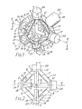
- the actual body of the laser gyroscope is produced from a cube of dielectric material having a low coefficient of expansion, one such material being that known under the trade name Zerodur and which is a glass ceramic having an extremely low coefficient of expansion. This material is also transparent which is why internal detail is seen in Figure 1.
- the faces of the cube of material are indicated at 1, 2, 3, 4, 5 and 6 and the three axes X, Y and Z pass through the centre of opposed pairs of faces.
- Three cavities (generally indicated at 7X, 7Y and 7Z in Figure 1) are formed in the cube of material at right angles to the respective axes X, Y and Z and each cavity is in the form of a square having four equal limbs 8 as seen in Figure 2.
- the cavity 7X has been shaded and the cavity 7Z cross hatched in Figure 1.
- the limbs 8 of the three cavities are produced by drilling 1 mm. diameter holes from the centre of each face 1-6 to the centre of each of the four adjacent faces.
- each face 1-6 becomes a cavity corner which is common to two cavities, all three cavities 7X, 7Y and 7Z therefore being interconnected.
- the length of each cavity limb 8 in this embodiment is 40 mm. which gives a cube size of 40 ⁇ 2 mm.
- the cavity limbs 8 are drilled with the cube of material in its basic form and not yet cut away to produce the shape seen in Figures 1 and 2. This greatly facilitates these machining operations which are followed by drilling 8 mm. diameter holes from the centre of each face 1-6, and at right angles thereto, the holes 9 and 11 drilled from each pair of opposed faces being of different lengths.
- Each of the three holes 9 extends to the centre of the cube and hence intersects the other two holes 9, whilst each of the three holes 8 stops short of the cube centre and is thus a blind bore.
- the final drilling operations are by way of providing a hole from the face 12 on which the cathode 14 is mounted to the centre of the cube, so as to link all three cavities 7X, 7Y and 7Z, as far as the cathode is concerned, via the holes 9, and providing holes 15 extending from the faces 12 on which the anodes 13 are mounted to the adjacent cavity limbs 8.
- Figure 2 shows both anodes 13 of the cavity 7Y to illustrate the arrangement but it should be noted that the right-hand anode is above the plane of the section of Figure 2 and would not normally be shown.
- Each cavity 7X, 7Y and 7Z has two anodes 13 (only one for each cavity being seen in Figure 1) disposed in the pair of opposed limbs 8 which extend between a hole 9 and a hole 11 and offset as close as possible to the hole 11 as is best seen in Figure 2.
- the anode-cathode separation is maximised which is desirable in order to achieve adequate gain which is proportional to that separation and to the anode-cathode current, and inversely proportional to the cavity limb diameter.
- anode-cathode separation is maximised, there is a risk of anode-to-anode discharge between cavities on start up and means to prevent this may have to be employed.
- visible discharge takes place only in the opposed limbs 8 of each cavity which interconnect with the related anodes 13, it being appreciated that the cavities are filled, after final assembly, with a gas, such as a helium/neon mix, which supports lasing action.
- One of the anodes 13 is fitted with a fill tube 16 for the gas and a getter 10 is provided in one of the holes 11.
- the getter may be of the light-activated, non- evaporable, zirconium-carbon type or one of the heat- activated type, for example, and is operable to maintain fill gas purity over a long period of time.
- a mirror is provided at each corner of each cavity 7 X , 7Y and 7Z but as each corner of one cavity coincides with one corner of another cavity by virtue of the provision of the holes 9 and 11, there is a requirement for only six mirrors which is half the total number of cavity corners. More specifically, three path length control mirrors 17 are sealed to the respective centres of the cube faces 1, 3 and 6 (so as to serve the cavities 7Y, 7Z; 7X, 7Y; and 7X, 7Z respectively) and three output mirrors 18 are sealed to the cube faces 2, 4 and 5 (so as to serve the cavities 7Y, 7Z; 7X, 7Y;and 7X, 7Z; respectively).
- the mirrors 17 may be curved or plain and are preferably of the diaphragm type movable by a piezo-electric transducer mounted adjacent the mirror in a housing 20 to compensate for any change in path length of a cavity which may occur-in operation of the gyroscope due to a number of well known factors.
- two of the three path length control mirrors 17 lie in the plane thereof and any adjustment is in the same sense as far as that cavity is concerned but the third mirror 17 not in the plane of that cavity will be adjusted in the opposite sense. Accordingly, path length control has to be effected by adjusting all three mirrors 17 simultaneously, this being achieved by an electronic circuit (not shown) which provides the signals for the piezo-electric transducers which in turn move the diaphragms of the mirrors 17.
- the output mirrors 18 may also be curved or plain and each has a conventional combiner-prism 19 attached thereto to provide fringes for a double element photodetector 21 associated therewith.
- the detectors 21 also provide feedback for path length control of the cavities 7X, 7Y and 7Z.
- the combiner prism 19 is oriented so as to operate on the light beams of one of the two associated cavities. For example, the combiner prism 19 seen in the eight o'clock position in Figure 1 outputs the light beam from cavity 7Y and not cavity 7X which it also serves.
- a mirror 17, 18 In order for a mirror 17, 18 to serve two of the cavities 7X, 7Y and 7Z, it has to be oriented so that its normal lies in both cavity planes and bisects the angles of . the associated cavity corners. This means that some possible cavity arrangements as regards coinciding corners are not acceptable since they will be such that the mirror normal does not lie in the cavity planes concerned and/or do not bisect the related cavity corners. However, there is no difficulty in these respects with the illustrated arrangement.
- the sealing of the anodes 13, cathode 14 and mirrors 17 and 18 to the respective faces of the block of material can be effected by any technique which will provide a gas- tight seal.
- the problem of lock-in can be obviated by imparting a bias to the ring laser gyroscope to ensure that operation is on a linear portion of the graph of frequency difference versus rotational rate, whereby low rotational rates can be detected.
- this bias is effected by subjecting the gyroscope to mechanical osciallation about an axis 22 which extends through one pair of opposed corners of the original cube of material.
- the so-called "dither" technique is well known and will not be described further.
- the type of bias used for the gyroscope does not form part of the present invention.
- the dither axis 22 extends at an angle to each of the sensitive axes X, Y, Z of the gyroscope and hence there will be a component of the mechanical osciallation about all three axes which is essential.
- the. anodes 13 and the cathode 14 are energised to effect, as described, laser discharge in each cavity 7X, 7Y and 7Z, whereby two beams of light are propagated around each cavity in opposite directions, being directed around the cavity by the corner mirrors 17 and 18.
- the two beams of light are combined by the combiner prism 19 associated with each cavity and in the absence of rotation of the gyroscope about the sensitive axis associated with a cavity, the detector 21 will not see any interference fringes arising from the two combined beams.
- the present invention effects a reduction in the number of mirrors which have to be employed in a multi-axis ring laser gyroscope and in the case of the illustrated embodiment there is a 50% saving. Even in relation to the more normal use of three-corner cavities there is a 33 1/3% saving, both savings being very significant in terms of cost.
- advantages flow from the basic inventive concept which, in relation to the illustrated embodiment, are as follows:
Landscapes
- Physics & Mathematics (AREA)
- Engineering & Computer Science (AREA)
- Electromagnetism (AREA)
- Optics & Photonics (AREA)
- Power Engineering (AREA)
- General Physics & Mathematics (AREA)
- Radar, Positioning & Navigation (AREA)
- Remote Sensing (AREA)
- Plasma & Fusion (AREA)
- Gyroscopes (AREA)
- Lasers (AREA)
Applications Claiming Priority (2)
| Application Number | Priority Date | Filing Date | Title |
|---|---|---|---|
| GB8015477A GB2076213B (en) | 1980-05-09 | 1980-05-09 | Ring laser gyroscopes |
| GB8015477 | 1980-05-09 |
Publications (2)
| Publication Number | Publication Date |
|---|---|
| EP0040004A1 true EP0040004A1 (de) | 1981-11-18 |
| EP0040004B1 EP0040004B1 (de) | 1983-03-30 |
Family
ID=10513325
Family Applications (1)
| Application Number | Title | Priority Date | Filing Date |
|---|---|---|---|
| EP81301685A Expired EP0040004B1 (de) | 1980-05-09 | 1981-04-16 | Ring-Laser-Gyroskop |
Country Status (7)
| Country | Link |
|---|---|
| US (1) | US4407583A (de) |
| EP (1) | EP0040004B1 (de) |
| JP (1) | JPS574185A (de) |
| CA (1) | CA1164987A (de) |
| DE (1) | DE3160138D1 (de) |
| GB (1) | GB2076213B (de) |
| IN (1) | IN155880B (de) |
Cited By (8)
| Publication number | Priority date | Publication date | Assignee | Title |
|---|---|---|---|---|
| FR2525343A1 (fr) * | 1982-04-16 | 1983-10-21 | Singer Co | Gyroscope monolithique a laser en anneau a trois axes |
| FR2542867A1 (fr) * | 1983-03-17 | 1984-09-21 | Singer Co | Controleur de la longueur de trajet pour ensemble gyroscopique a laser en anneaux a trois axes |
| EP0209279A1 (de) * | 1985-06-27 | 1987-01-21 | British Aerospace Public Limited Company | Ringlaserkreisel |
| EP0130766A3 (en) * | 1983-06-29 | 1987-06-16 | British Aerospace Public Limited Company | Multiple axis ring laser gyroscopes |
| FR2605101A1 (fr) * | 1986-10-14 | 1988-04-15 | Thomson Csf | Interferometre en anneau a fibres optiques a trois axes |
| EP0320101A1 (de) * | 1987-12-10 | 1989-06-14 | British Aerospace Public Limited Company | Ringlaserkreisel |
| EP0320102A1 (de) * | 1987-12-10 | 1989-06-14 | British Aerospace Public Limited Company | Ringlaserkreisel |
| EP0292106A3 (en) * | 1987-04-06 | 1990-08-16 | Litton Systems, Inc. | Inertial sensor |
Families Citing this family (16)
| Publication number | Priority date | Publication date | Assignee | Title |
|---|---|---|---|---|
| USRE34490E (en) * | 1980-03-21 | 1993-12-28 | Sextant Avionique | Compact, integral, 6-mirror, triaxial, laser rate gyro |
| FR2512198A1 (fr) * | 1980-03-21 | 1983-03-04 | Sfena | Gyrometre laser triaxial, monobloc, compact a six miroirs |
| US5412475A (en) * | 1982-08-27 | 1995-05-02 | Raytheon Company | Diagonal pathlength control |
| US5333046A (en) * | 1982-08-27 | 1994-07-26 | Raytheon Company | Diagonal pathlength control |
| WO1987002140A1 (fr) * | 1982-11-20 | 1987-04-09 | Mueller Paul | Procede de determination de la vitesse de rotation |
| US4534648A (en) * | 1983-11-07 | 1985-08-13 | The United States Of America As Represented By The Secretary Of The Navy | Gyro sensor block suspension |
| US5004343A (en) * | 1986-03-14 | 1991-04-02 | Raytheon Company | Multiple ring paths in one block |
| US4837774A (en) * | 1987-09-29 | 1989-06-06 | Litton Systems, Inc. | Common mirror triaxial ring laser gyroscope having a single internal cathode |
| SE461758B (sv) * | 1987-10-13 | 1990-03-19 | Trumpf Gmbh & Co | Co -effektlaser |
| US5371589A (en) * | 1989-05-30 | 1994-12-06 | Litton Systems, Inc. | Triaxial ring laser gyroscope with independent cavity length control |
| US5448354A (en) * | 1991-07-29 | 1995-09-05 | Rockwell International Corporation | Acceleration distortion resistant ring laser gyro |
| FR2902870B1 (fr) * | 2006-06-23 | 2008-09-05 | Thales Sa | Dispositif d'amelioration de la duree de vie d'un gyrometre triaxial |
| JP5007799B2 (ja) * | 2006-12-21 | 2012-08-22 | 株式会社Ihi | 3次元ディスクレーザ |
| US20100315698A1 (en) * | 2007-04-10 | 2010-12-16 | Dixon George J | Modular ring resonator |
| CN105674973B (zh) * | 2014-11-17 | 2019-06-28 | 中国航空工业第六一八研究所 | 一种激光陀螺内置吸气剂激活方法 |
| CN119492367B (zh) * | 2024-11-25 | 2025-06-13 | 中国人民解放军国防科技大学 | 一种量子噪声压缩型激光陀螺 |
Citations (3)
| Publication number | Priority date | Publication date | Assignee | Title |
|---|---|---|---|---|
| US3503688A (en) * | 1966-08-15 | 1970-03-31 | Honeywell Inc | Multiple axis laser angular rate sensor |
| FR2430598A1 (fr) * | 1978-07-03 | 1980-02-01 | Litton Systems Inc | Gyroscope a laser en anneau |
| GB2038081A (en) * | 1978-12-26 | 1980-07-16 | Litton Systems Inc | Ring laser |
Family Cites Families (1)
| Publication number | Priority date | Publication date | Assignee | Title |
|---|---|---|---|---|
| US3484169A (en) * | 1968-01-04 | 1969-12-16 | Singer General Precision | Motion sensing apparatus |
-
1980
- 1980-05-09 GB GB8015477A patent/GB2076213B/en not_active Expired
-
1981
- 1981-04-10 IN IN214/DEL/81A patent/IN155880B/en unknown
- 1981-04-16 DE DE8181301685T patent/DE3160138D1/de not_active Expired
- 1981-04-16 EP EP81301685A patent/EP0040004B1/de not_active Expired
- 1981-04-17 US US06/255,018 patent/US4407583A/en not_active Expired - Lifetime
- 1981-04-23 CA CA000376107A patent/CA1164987A/en not_active Expired
- 1981-05-09 JP JP7003781A patent/JPS574185A/ja active Granted
Patent Citations (3)
| Publication number | Priority date | Publication date | Assignee | Title |
|---|---|---|---|---|
| US3503688A (en) * | 1966-08-15 | 1970-03-31 | Honeywell Inc | Multiple axis laser angular rate sensor |
| FR2430598A1 (fr) * | 1978-07-03 | 1980-02-01 | Litton Systems Inc | Gyroscope a laser en anneau |
| GB2038081A (en) * | 1978-12-26 | 1980-07-16 | Litton Systems Inc | Ring laser |
Cited By (15)
| Publication number | Priority date | Publication date | Assignee | Title |
|---|---|---|---|---|
| DE3313434A1 (de) * | 1982-04-16 | 1983-11-03 | The Singer Co., 06904 Stamford, Conn. | Monolithischer ringlaser mit drei eingangsachsen |
| FR2525343A1 (fr) * | 1982-04-16 | 1983-10-21 | Singer Co | Gyroscope monolithique a laser en anneau a trois axes |
| FR2542867A1 (fr) * | 1983-03-17 | 1984-09-21 | Singer Co | Controleur de la longueur de trajet pour ensemble gyroscopique a laser en anneaux a trois axes |
| US4762415A (en) * | 1983-06-29 | 1988-08-09 | British Aerospace Plc | Multiple axis ring laser gyroscopes |
| EP0130766A3 (en) * | 1983-06-29 | 1987-06-16 | British Aerospace Public Limited Company | Multiple axis ring laser gyroscopes |
| US4839903A (en) * | 1985-06-27 | 1989-06-13 | British Aerospace Public Limited Company | Ring laser gyroscopes |
| EP0209279A1 (de) * | 1985-06-27 | 1987-01-21 | British Aerospace Public Limited Company | Ringlaserkreisel |
| EP0266249A1 (de) * | 1986-10-14 | 1988-05-04 | Thomson-Csf | Dreiachsiges optisches Fiberringinterferometer |
| FR2605101A1 (fr) * | 1986-10-14 | 1988-04-15 | Thomson Csf | Interferometre en anneau a fibres optiques a trois axes |
| US4815853A (en) * | 1986-10-14 | 1989-03-28 | Thomson-C.S.F. | Three-axis fiber-optic ring interferometer |
| EP0292106A3 (en) * | 1987-04-06 | 1990-08-16 | Litton Systems, Inc. | Inertial sensor |
| EP0320101A1 (de) * | 1987-12-10 | 1989-06-14 | British Aerospace Public Limited Company | Ringlaserkreisel |
| EP0320102A1 (de) * | 1987-12-10 | 1989-06-14 | British Aerospace Public Limited Company | Ringlaserkreisel |
| US4973161A (en) * | 1987-12-10 | 1990-11-27 | British Aerospace Public Limited Company | Ring laser gyroscopes |
| US5394241A (en) * | 1987-12-10 | 1995-02-28 | British Aerospace Public Limited Company | Multiple axis ring laser gyroscope with longitudinal excitation |
Also Published As
| Publication number | Publication date |
|---|---|
| GB2076213A (en) | 1981-11-25 |
| US4407583A (en) | 1983-10-04 |
| DE3160138D1 (en) | 1983-05-05 |
| EP0040004B1 (de) | 1983-03-30 |
| JPS574185A (en) | 1982-01-09 |
| IN155880B (de) | 1985-03-23 |
| GB2076213B (en) | 1983-08-17 |
| CA1164987A (en) | 1984-04-03 |
| JPS6351392B2 (de) | 1988-10-13 |
Similar Documents
| Publication | Publication Date | Title |
|---|---|---|
| US4407583A (en) | Ring laser gyroscopes | |
| US4477188A (en) | Monolithic three axis ring laser gyroscope | |
| US5757490A (en) | Compact three-axis ring laser gyroscope | |
| EP0292106B1 (de) | Inertialsensor | |
| GB2038081A (en) | Ring laser | |
| US4585346A (en) | Pathlength controller for three-axis ring laser gyroscope assembly | |
| US5430755A (en) | Pressure-equalized self-compensating discharge configuration for triangular ring laser gyroscopes | |
| CA1309155C (en) | Ring laser | |
| CA1243764A (en) | Low cost ring laser angular rate sensor | |
| US4973161A (en) | Ring laser gyroscopes | |
| US5371589A (en) | Triaxial ring laser gyroscope with independent cavity length control | |
| US4727638A (en) | Low cost ring laser angular rate sensor | |
| US4839903A (en) | Ring laser gyroscopes | |
| US5116128A (en) | Mirror transducer assembly for ring laser gyroscope | |
| US4325033A (en) | Pneumatically dithered laser gyro | |
| CA1212748A (en) | Ring laser rotational rate sensor | |
| US4837774A (en) | Common mirror triaxial ring laser gyroscope having a single internal cathode | |
| US5020911A (en) | Ring laser gyro comprising rotary oscillation apparatus | |
| EP0320102B1 (de) | Ringlaserkreisel | |
| EP0130766B1 (de) | Mehrachsiger Ringlaserkreisel | |
| US4864586A (en) | Hollow cathode glow discharge ring laser block and electrode structure for ring laser angular rate sensors | |
| US5116130A (en) | Ring laser gyroscope mount | |
| CN222993734U (zh) | 一种小型化高精度激光陀螺仪 | |
| USRE34490E (en) | Compact, integral, 6-mirror, triaxial, laser rate gyro | |
| Morrison et al. | Missile Laser Gyro Rate Sensor |
Legal Events
| Date | Code | Title | Description |
|---|---|---|---|
| PUAI | Public reference made under article 153(3) epc to a published international application that has entered the european phase |
Free format text: ORIGINAL CODE: 0009012 |
|
| AK | Designated contracting states |
Designated state(s): DE FR NL SE |
|
| 17P | Request for examination filed |
Effective date: 19811005 |
|
| GRAA | (expected) grant |
Free format text: ORIGINAL CODE: 0009210 |
|
| AK | Designated contracting states |
Designated state(s): DE FR NL SE |
|
| PG25 | Lapsed in a contracting state [announced via postgrant information from national office to epo] |
Ref country code: SE Effective date: 19830330 |
|
| REF | Corresponds to: |
Ref document number: 3160138 Country of ref document: DE Date of ref document: 19830505 |
|
| ET | Fr: translation filed | ||
| PGFP | Annual fee paid to national office [announced via postgrant information from national office to epo] |
Ref country code: NL Payment date: 20000313 Year of fee payment: 20 |
|
| PGFP | Annual fee paid to national office [announced via postgrant information from national office to epo] |
Ref country code: DE Payment date: 20000316 Year of fee payment: 20 |
|
| PGFP | Annual fee paid to national office [announced via postgrant information from national office to epo] |
Ref country code: FR Payment date: 20000426 Year of fee payment: 20 |
|
| PG25 | Lapsed in a contracting state [announced via postgrant information from national office to epo] |
Ref country code: NL Free format text: LAPSE BECAUSE OF EXPIRATION OF PROTECTION Effective date: 20010416 |
|
| NLV7 | Nl: ceased due to reaching the maximum lifetime of a patent |
Effective date: 20010416 |
|
| PLBE | No opposition filed within time limit |
Free format text: ORIGINAL CODE: 0009261 |
|
| STAA | Information on the status of an ep patent application or granted ep patent |
Free format text: STATUS: NO OPPOSITION FILED WITHIN TIME LIMIT |