EP0040059A2 - Vorrichtung für kontinuierliches und direktes Messen der Temperatur der Meeresoberfläche - Google Patents
Vorrichtung für kontinuierliches und direktes Messen der Temperatur der Meeresoberfläche Download PDFInfo
- Publication number
- EP0040059A2 EP0040059A2 EP81302041A EP81302041A EP0040059A2 EP 0040059 A2 EP0040059 A2 EP 0040059A2 EP 81302041 A EP81302041 A EP 81302041A EP 81302041 A EP81302041 A EP 81302041A EP 0040059 A2 EP0040059 A2 EP 0040059A2
- Authority
- EP
- European Patent Office
- Prior art keywords
- central
- water
- temperature
- arm
- floating
- Prior art date
- Legal status (The legal status is an assumption and is not a legal conclusion. Google has not performed a legal analysis and makes no representation as to the accuracy of the status listed.)
- Granted
Links
Images

Classifications
-
- G—PHYSICS
- G01—MEASURING; TESTING
- G01K—MEASURING TEMPERATURE; MEASURING QUANTITY OF HEAT; THERMALLY-SENSITIVE ELEMENTS NOT OTHERWISE PROVIDED FOR
- G01K1/00—Details of thermometers not specially adapted for particular types of thermometer
- G01K1/08—Protective devices, e.g. casings
-
- G—PHYSICS
- G01—MEASURING; TESTING
- G01C—MEASURING DISTANCES, LEVELS OR BEARINGS; SURVEYING; NAVIGATION; GYROSCOPIC INSTRUMENTS; PHOTOGRAMMETRY OR VIDEOGRAMMETRY
- G01C13/00—Surveying specially adapted to open water, e.g. sea, lake, river or canal
-
- G—PHYSICS
- G01—MEASURING; TESTING
- G01K—MEASURING TEMPERATURE; MEASURING QUANTITY OF HEAT; THERMALLY-SENSITIVE ELEMENTS NOT OTHERWISE PROVIDED FOR
- G01K1/00—Details of thermometers not specially adapted for particular types of thermometer
- G01K1/16—Special arrangements for conducting heat from the object to the sensitive element
-
- G—PHYSICS
- G01—MEASURING; TESTING
- G01K—MEASURING TEMPERATURE; MEASURING QUANTITY OF HEAT; THERMALLY-SENSITIVE ELEMENTS NOT OTHERWISE PROVIDED FOR
- G01K13/00—Thermometers specially adapted for specific purposes
Definitions
- the present invention relates to an apparatus for the continuous and direct measurement of the temperature of the sea in its. upper superficial part.
- the temperature of the surface of a lake or other water surfaces may also be directly detected with such apparatus.
- the apparatus is adapted to lie on the water surface so that the . sensing portion thereof contacts the upper superficial layer of the water.
- the object of the present invention is the realization of a temperature detector which is light, flexible, highly buoyant and able to follow the micromovements of the water surface without leaving the ultra surface of the water. It is understood that once a certain sea state is exceeded, the surface layer of water . is replaced by a mixed layer of a given thickness, and that then the temperature of this layer can be. measured by conventional means, such as a nornal or reversing thermometer. Owing to the fact that its use is desirably continuous (i.e. uninterrupted), the detector- should not be fragile and should chemically resist, for its nature and structure, hydrocarbons and other pollutants. It should not be affected in its structure by sun rays in the measurament of temperature. The length of the detector should be sufficient to give it a degree of flexibility without losing contact with the water surface. It should also be freely deformable and present the minimum resistance to wind and wave.
- an apparatus for the continuous and direct measurement of the temperature of the upper superficial layer of the surface of the sea or other water surface which apparatus comprises a central floating member and at least one arm connecting the central member to at least one peripheral floating element, the or each arm containing a thermal collector for transmitting heat to at least one temperature detector carried by the apparatus, wherein the central member and the or each peripheral floating element are adapted to maintain the apparatus on the water surface while at least a part of the or each aim is in contact with and senses the upper superificial layer of the water, and wherein electrical means are provided in the apparatus for the storage and/or transmission of temperature data from the or each temperature detector.
- the extremities of the detector are well adapted to exploit the phenomena of the surface tension between the water and the material constituting the extremities, and its essential field of temperature measurement concerns the ultra superficial-layer of the water surface.
- the present apparatus is freely connected to a buoy at a distance of at least 1 or 2 metres and follows its drifting movements.
- An interlaced hollow nylon cable forming the mechanical connection between the two also carries electrical connections from the apparatus to the buoy.
- the apparatus of the present invention when connected to and dragged by a drifting buoy, transmits the temperature signals to the said buoy. From the buoy, temperature data are transmitted to a terrestrial station, to a ship, to a rig or a platform, or to a satellite where they are then correlated with remote infrared radiometric measurements.
- the present apparatus can operate independently of any buoy by including therein means for converting the temperature data received from its detector(s) into signals to be transmitted telegraphically to a receiving station.
- this means would comprise a microprocessor, microbattery and microemitter, and would be preferably located in the central floating -member.
- the present apparatus is designed to gather information concerning the thermal exchange between a water surface and its local atmosphere, it is often desirable to include in the apparatus means for detecting the temperature of the air immediately above the surface of the water being sensed, and also the temperature of the water at a level below this superficial surface.
- Suitable detector for these purposes can be incorporated conveniently in the central floating member.
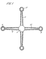
- the central floating member 1 is connected via four arms 2 to four peripheral floating elements 3.
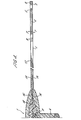
- These peripheral floating elements preferably of a circular form, and having a thickness of some fractions of a millimetre, include a volume 4 of air which, in the embodiment of Figure 4 is obtained by a washer 5 made of P.V.C.
- the floating elements 3 are constituted by two plastics discs 7 circumferentially soldered together, as seen in 8 of Figures 1 and 4.
- the washer prevents the discs from being in contact and always preserves a small volume of air between them which provides an upthrust for element 3 and increases the adherence to the--water surface for the relative extension of the disc 7 and to the enlarged surface tension.
- the floating action of the floating element 3 is obtained by utilising instead of the washer 5', some superimposed woven plastics discs.
- the aim is to obtain a small volume of air for enhancing the floating action using light materials.
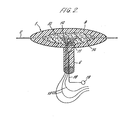
- the body of the central floating member 1, whose vertical section is shown in Figure 2, is composed of an external resin 9 and an internal insulating, expanded resin 10.
- the resin 9, which is externally metallized over all its surface and treated against biofouling, possesses a certain hardness and has a relative density of 0.6; whilst the internal resin 10 has a relative density of 0.3.
- the chosen densities are selected according to the desired degree of floating of the member 1. If we desire to lower its floating level, we may choose a resin with a greater density.
- thermoconducting resin 12 In the centre of the volume of the central floating member 1 and internally of the insulating resin 10 is disposed a termistance 11 (i.e. a thermoresistance), covered by a thermoconducting resin 12.
- a detector for sensing the temperature of the air immediately above the superficial surface can be installed in the central floating member.
- a cylindrical appendage 6 is carried, providing increased stability to the whole apparatus. It is made of a resin and vertically crossed by electrical cables 13, connected to the thermistance, and by an Inox cable 18 bearing a ring 19 for the mechanical connection with the buoy (not shown). This connection is made by means of a nylon cable. When desired, a detector for sensing the temperature of water below the superficial surface can be installed in this appendage.
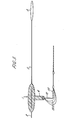
- each arm (see Figure 4) is constituted by a transparent double plastics blade 15 which is very thin, i.e. 8 x 10 -2 mm, and is composed of, for example, a sheet of polypropylene and polyethylene, peripherally soldered together.
- the length of each arm is about 171 mm and its width, which is 26 mm near the floating member 1, decreases slightly to 16 mm near the element 3.
- a gold band 14 which is the thermal collector and is in contact with the thermistance 11 at one end and extends nearly to the floating element 3 at the other end.
- a band of coated paper 16 protects the gold band 14 in the region where it enters the floating member 1, preventing its breakage when subjected to wave action and also serving as a thermal insulator.
- An aluminium band 17 is then. superimposed on the paper band 16 and serves as a shield against the sun's rays.
- FIG. 5 is shown a variant of the present temperature detector.
- the thermoresistance 11 is placed inside a peripheral floating element 3, instead of in the central floating member 1 which contains now only the electrical connections with the buoy.
- the three arms 2 and the peripheral elements 3 are only for the purpose of floating and are constituted by plastics sandwiches enclosing small volumes of air in the manner previously described, e.g. with woven plastics washers and discs.
- thermoresistances may be placed inside the peripheral floating elements other than the illustrated element 3, in order to be able to average out local temperature variations.
Landscapes
- Physics & Mathematics (AREA)
- General Physics & Mathematics (AREA)
- Life Sciences & Earth Sciences (AREA)
- Hydrology & Water Resources (AREA)
- Engineering & Computer Science (AREA)
- Radar, Positioning & Navigation (AREA)
- Remote Sensing (AREA)
- Measuring Temperature Or Quantity Of Heat (AREA)
- Testing Or Calibration Of Command Recording Devices (AREA)
- Crystals, And After-Treatments Of Crystals (AREA)
- Arrangements For Transmission Of Measured Signals (AREA)
Priority Applications (1)
| Application Number | Priority Date | Filing Date | Title |
|---|---|---|---|
| AT81302041T ATE10680T1 (de) | 1980-05-09 | 1981-05-08 | Vorrichtung fuer kontinuierliches und direktes messen der temperatur der meeresoberflaeche. |
Applications Claiming Priority (2)
| Application Number | Priority Date | Filing Date | Title |
|---|---|---|---|
| GB8015401 | 1980-05-09 | ||
| GB8015401 | 1980-05-09 |
Publications (3)
| Publication Number | Publication Date |
|---|---|
| EP0040059A2 true EP0040059A2 (de) | 1981-11-18 |
| EP0040059A3 EP0040059A3 (en) | 1981-12-02 |
| EP0040059B1 EP0040059B1 (de) | 1984-12-05 |
Family
ID=10513311
Family Applications (1)
| Application Number | Title | Priority Date | Filing Date |
|---|---|---|---|
| EP81302041A Expired EP0040059B1 (de) | 1980-05-09 | 1981-05-08 | Vorrichtung für kontinuierliches und direktes Messen der Temperatur der Meeresoberfläche |
Country Status (7)
| Country | Link |
|---|---|
| US (1) | US4410282A (de) |
| EP (1) | EP0040059B1 (de) |
| JP (1) | JPS5730917A (de) |
| AT (1) | ATE10680T1 (de) |
| AU (1) | AU7026881A (de) |
| DE (1) | DE3167563D1 (de) |
| GB (1) | GB2075689B (de) |
Families Citing this family (11)
| Publication number | Priority date | Publication date | Assignee | Title |
|---|---|---|---|---|
| JPS6223998A (ja) * | 1985-07-22 | 1987-01-31 | Ishikawajima Harima Heavy Ind Co Ltd | 鉄鋼構造物の防食被覆方法 |
| US4738549A (en) * | 1986-04-03 | 1988-04-19 | Plimpton R Gregory | Pool thermometer |
| US5020919A (en) * | 1990-04-24 | 1991-06-04 | Wisconsin Alumni Research Foundation | Heat flow sensing apparatus and method |
| US6161075A (en) * | 1998-07-09 | 2000-12-12 | Itt Manufacturing Enterprises, Inc. | Method for determining the accuracy of measured environmental data parameters |
| GB0209203D0 (en) * | 2002-04-23 | 2002-06-05 | Mcgowan Scanlon Martin | Monitoring device |
| US7380453B1 (en) | 2006-09-16 | 2008-06-03 | Advanced Design Consulting Usa, Inc | Undersea data logging device with automated data transmission |
| CN103439025B (zh) * | 2013-09-05 | 2015-12-23 | 中国科学院南海海洋研究所 | 水体皮温-表温同步测量装置对卫星遥感定标的方法 |
| US9709396B2 (en) * | 2015-09-25 | 2017-07-18 | Metocean Telematics Limited | Air deployable ocean drifter buoy |
| CN110146184B (zh) * | 2019-06-14 | 2020-05-05 | 自然资源部第一海洋研究所 | 防浪涌浮体、水体温度测量装置和综合测量系统 |
| CN110715749B (zh) * | 2019-09-30 | 2021-03-16 | 河海大学 | 适用于复杂水域的三维水温智能监测装置、系统和方法 |
| CN115452200B (zh) * | 2022-09-19 | 2023-04-28 | 河海大学 | 一种水环境温度测量工具 |
Family Cites Families (12)
| Publication number | Priority date | Publication date | Assignee | Title |
|---|---|---|---|---|
| US2040292A (en) * | 1934-04-28 | 1936-05-12 | Taylor Instrument Co | Thermometer |
| US2282277A (en) * | 1940-09-20 | 1942-05-05 | Cooper Oven Thermometer Compan | Thermometer |
| US3273393A (en) * | 1964-03-24 | 1966-09-20 | Douglas Aircraft Co Inc | Bathythermograph |
| US3561267A (en) * | 1964-04-10 | 1971-02-09 | Gen Motors Corp | Bathythermometer |
| US3587309A (en) * | 1969-06-12 | 1971-06-28 | Trident Engineering Associates | Aero-hydro interface measuring system |
| US3596512A (en) * | 1970-01-05 | 1971-08-03 | Sippican Corp | Expendable air probe |
| US3674225A (en) * | 1970-07-09 | 1972-07-04 | Us Army | Buoy |
| US3670572A (en) * | 1971-06-11 | 1972-06-20 | Us Navy | Air-sea interface temperature measuring apparatus |
| FR2330410A1 (fr) * | 1975-11-07 | 1977-06-03 | Boeuf Guy Le | Capteur de temperature destine a la regulation du chauffage d'un fluide sterile administre a un patient |
| US4030361A (en) * | 1975-12-22 | 1977-06-21 | Fortune Jeffrey L | Floating bath water temperature measuring instrument |
| US4123813A (en) * | 1977-01-24 | 1978-11-07 | Adams Ronald J | Buoyant float and flag assembly |
| US4228556A (en) * | 1978-04-10 | 1980-10-21 | Searls Henry H | Automatically energizable lifesaving equipment |
-
1981
- 1981-05-08 DE DE8181302041T patent/DE3167563D1/de not_active Expired
- 1981-05-08 AT AT81302041T patent/ATE10680T1/de active
- 1981-05-08 GB GB8114077A patent/GB2075689B/en not_active Expired
- 1981-05-08 AU AU70268/81A patent/AU7026881A/en not_active Abandoned
- 1981-05-08 JP JP6925281A patent/JPS5730917A/ja active Pending
- 1981-05-08 EP EP81302041A patent/EP0040059B1/de not_active Expired
- 1981-05-11 US US06/262,704 patent/US4410282A/en not_active Expired - Fee Related
Also Published As
| Publication number | Publication date |
|---|---|
| AU7026881A (en) | 1981-11-12 |
| ATE10680T1 (de) | 1984-12-15 |
| US4410282A (en) | 1983-10-18 |
| DE3167563D1 (en) | 1985-01-17 |
| GB2075689A (en) | 1981-11-18 |
| JPS5730917A (en) | 1982-02-19 |
| EP0040059B1 (de) | 1984-12-05 |
| GB2075689B (en) | 1984-04-04 |
| EP0040059A3 (en) | 1981-12-02 |
Similar Documents
| Publication | Publication Date | Title |
|---|---|---|
| EP0040059B1 (de) | Vorrichtung für kontinuierliches und direktes Messen der Temperatur der Meeresoberfläche | |
| US6466719B2 (en) | Optical temperature sensing arrangement for towed cable | |
| US3511090A (en) | Fluent material level sensor | |
| Wilheit | The effect of wind on the microwave emission from the ocean's surface at 37 GHz | |
| Jacobson et al. | Wet Reflectors in Millimeter-Wave Radiometry-Expenrment and Theory | |
| Thomann | Experimental results of the remote sensing of sea-surface salinity at 21-cm wavelength | |
| Sybrandy et al. | Global drifter programme barometer drifter design reference | |
| US3983750A (en) | Fluid level sensing device | |
| US3301047A (en) | Wave gage arrays for obtaining ocean-wave spectra | |
| US3336799A (en) | Free-floating apparatus for measuring and telemetering sea-wave characteristics | |
| JP2004191268A (ja) | ブイ、ブイ装置及び波浪情報計測装置 | |
| CA1163829A (en) | Apparatus for continuous and direct measurement of the sea surface temperature | |
| US5020919A (en) | Heat flow sensing apparatus and method | |
| US3534599A (en) | Expendable ocean-wave meter | |
| US3670572A (en) | Air-sea interface temperature measuring apparatus | |
| Johannessen et al. | COAST WATCH-95: ERS-1/2 SAR applications of mesoscale upper ocean and atmospheric boundary layer processes off the coast of Norway | |
| US3307399A (en) | Surface-piercing mast for measuring the depth of a submerged vessel | |
| RU2822208C1 (ru) | Устройство для снятия вертикального температурного разреза в водной среде | |
| Blume et al. | Submarine fresh water outflow detection with a dual-frequency microwave and an infrared radiometer system | |
| Reynolds | A simple meteorological buoy with satellite telemetry | |
| Constans et al. | The continuous measurement of the temperature of the upper layer of the sea—A practical approach | |
| Boyle | Measurement of net ocean surface heat flux, solar irradiance and temperature during the CBLAST-Low field program using a novel surface contact multi-sensor float | |
| US3587309A (en) | Aero-hydro interface measuring system | |
| Schwab et al. | Intercomparison of wave measurements obtained from a NOMAD buoy and from a Waverider buoy in Lake Erie | |
| EP0032604A1 (de) | Radar-Reflektor |
Legal Events
| Date | Code | Title | Description |
|---|---|---|---|
| PUAI | Public reference made under article 153(3) epc to a published international application that has entered the european phase |
Free format text: ORIGINAL CODE: 0009012 |
|
| PUAL | Search report despatched |
Free format text: ORIGINAL CODE: 0009013 |
|
| AK | Designated contracting states |
Designated state(s): AT BE CH DE FR IT LU NL SE |
|
| AK | Designated contracting states |
Designated state(s): AT BE CH DE FR IT LU NL SE |
|
| 17P | Request for examination filed |
Effective date: 19820125 |
|
| ITF | It: translation for a ep patent filed | ||
| GRAA | (expected) grant |
Free format text: ORIGINAL CODE: 0009210 |
|
| AK | Designated contracting states |
Designated state(s): AT BE CH DE FR IT LI LU NL SE |
|
| REF | Corresponds to: |
Ref document number: 10680 Country of ref document: AT Date of ref document: 19841215 Kind code of ref document: T |
|
| REF | Corresponds to: |
Ref document number: 3167563 Country of ref document: DE Date of ref document: 19850117 |
|
| ET | Fr: translation filed | ||
| PG25 | Lapsed in a contracting state [announced via postgrant information from national office to epo] |
Ref country code: AT Effective date: 19850508 |
|
| PG25 | Lapsed in a contracting state [announced via postgrant information from national office to epo] |
Ref country code: SE Effective date: 19850509 |
|
| PG25 | Lapsed in a contracting state [announced via postgrant information from national office to epo] |
Ref country code: LU Free format text: LAPSE BECAUSE OF NON-PAYMENT OF DUE FEES Effective date: 19850531 Ref country code: LI Effective date: 19850531 Ref country code: CH Effective date: 19850531 Ref country code: BE Effective date: 19850531 |
|
| PLBE | No opposition filed within time limit |
Free format text: ORIGINAL CODE: 0009261 |
|
| STAA | Information on the status of an ep patent application or granted ep patent |
Free format text: STATUS: NO OPPOSITION FILED WITHIN TIME LIMIT |
|
| BERE | Be: lapsed |
Owner name: EUROPEAN ATOMIC ENERGY COMMUNITY ( EURATOM) Effective date: 19850508 |
|
| PG25 | Lapsed in a contracting state [announced via postgrant information from national office to epo] |
Ref country code: NL Effective date: 19851201 |
|
| 26N | No opposition filed | ||
| NLV4 | Nl: lapsed or anulled due to non-payment of the annual fee | ||
| PG25 | Lapsed in a contracting state [announced via postgrant information from national office to epo] |
Ref country code: FR Free format text: LAPSE BECAUSE OF NON-PAYMENT OF DUE FEES Effective date: 19860131 |
|
| REG | Reference to a national code |
Ref country code: CH Ref legal event code: PL |
|
| PG25 | Lapsed in a contracting state [announced via postgrant information from national office to epo] |
Ref country code: DE Effective date: 19860201 |
|
| REG | Reference to a national code |
Ref country code: FR Ref legal event code: ST |
|
| EUG | Se: european patent has lapsed |
Ref document number: 81302041.9 Effective date: 19860728 |