EP0040100A1 - Ofen für feste Brennstoffe - Google Patents
Ofen für feste Brennstoffe Download PDFInfo
- Publication number
- EP0040100A1 EP0040100A1 EP81302111A EP81302111A EP0040100A1 EP 0040100 A1 EP0040100 A1 EP 0040100A1 EP 81302111 A EP81302111 A EP 81302111A EP 81302111 A EP81302111 A EP 81302111A EP 0040100 A1 EP0040100 A1 EP 0040100A1
- Authority
- EP
- European Patent Office
- Prior art keywords
- stove
- combustion
- opening
- air
- chamber
- Prior art date
- Legal status (The legal status is an assumption and is not a legal conclusion. Google has not performed a legal analysis and makes no representation as to the accuracy of the status listed.)
- Granted
Links
- 239000004449 solid propellant Substances 0.000 title abstract description 4
- 238000002485 combustion reaction Methods 0.000 claims abstract description 98
- 239000000446 fuel Substances 0.000 claims abstract description 50
- 239000003245 coal Substances 0.000 claims abstract description 9
- 239000002956 ash Substances 0.000 claims description 29
- 239000000567 combustion gas Substances 0.000 claims description 15
- XLYOFNOQVPJJNP-UHFFFAOYSA-N water Substances O XLYOFNOQVPJJNP-UHFFFAOYSA-N 0.000 claims description 8
- 235000002918 Fraxinus excelsior Nutrition 0.000 claims description 6
- 230000008021 deposition Effects 0.000 claims description 6
- 238000010438 heat treatment Methods 0.000 claims description 6
- 230000000694 effects Effects 0.000 claims description 5
- 229910001018 Cast iron Inorganic materials 0.000 claims description 4
- 239000002184 metal Substances 0.000 claims description 4
- 229910052751 metal Inorganic materials 0.000 claims description 4
- 239000007789 gas Substances 0.000 claims description 3
- 230000005484 gravity Effects 0.000 claims description 2
- 230000037431 insertion Effects 0.000 claims 1
- 238000003780 insertion Methods 0.000 claims 1
- 230000001737 promoting effect Effects 0.000 claims 1
- 230000002787 reinforcement Effects 0.000 claims 1
- 239000011521 glass Substances 0.000 abstract description 11
- 239000002023 wood Substances 0.000 abstract description 5
- 238000010411 cooking Methods 0.000 abstract description 3
- 239000005341 toughened glass Substances 0.000 abstract description 2
- 239000003039 volatile agent Substances 0.000 abstract 1
- 229910000831 Steel Inorganic materials 0.000 description 5
- 239000000463 material Substances 0.000 description 5
- 238000000034 method Methods 0.000 description 5
- 239000010959 steel Substances 0.000 description 5
- 230000036961 partial effect Effects 0.000 description 3
- WHRZCXAVMTUTDD-UHFFFAOYSA-N 1h-furo[2,3-d]pyrimidin-2-one Chemical compound N1C(=O)N=C2OC=CC2=C1 WHRZCXAVMTUTDD-UHFFFAOYSA-N 0.000 description 2
- 235000006173 Larrea tridentata Nutrition 0.000 description 2
- 244000073231 Larrea tridentata Species 0.000 description 2
- 238000010276 construction Methods 0.000 description 2
- 229960002126 creosote Drugs 0.000 description 2
- 230000008595 infiltration Effects 0.000 description 2
- 238000001764 infiltration Methods 0.000 description 2
- 239000000779 smoke Substances 0.000 description 2
- 230000007704 transition Effects 0.000 description 2
- 229920001342 Bakelite® Polymers 0.000 description 1
- OKTJSMMVPCPJKN-UHFFFAOYSA-N Carbon Chemical compound [C] OKTJSMMVPCPJKN-UHFFFAOYSA-N 0.000 description 1
- 241000196324 Embryophyta Species 0.000 description 1
- 241000357293 Leptobrama muelleri Species 0.000 description 1
- 238000013459 approach Methods 0.000 description 1
- 239000010425 asbestos Substances 0.000 description 1
- 239000004637 bakelite Substances 0.000 description 1
- 230000005540 biological transmission Effects 0.000 description 1
- 230000015572 biosynthetic process Effects 0.000 description 1
- 229910052799 carbon Inorganic materials 0.000 description 1
- 239000000919 ceramic Substances 0.000 description 1
- 238000004140 cleaning Methods 0.000 description 1
- 150000001875 compounds Chemical class 0.000 description 1
- 238000001816 cooling Methods 0.000 description 1
- 238000009826 distribution Methods 0.000 description 1
- 230000008030 elimination Effects 0.000 description 1
- 238000003379 elimination reaction Methods 0.000 description 1
- 239000003365 glass fiber Substances 0.000 description 1
- 239000003779 heat-resistant material Substances 0.000 description 1
- 230000001939 inductive effect Effects 0.000 description 1
- 230000002401 inhibitory effect Effects 0.000 description 1
- 238000007689 inspection Methods 0.000 description 1
- 238000009434 installation Methods 0.000 description 1
- 230000000737 periodic effect Effects 0.000 description 1
- 230000001376 precipitating effect Effects 0.000 description 1
- 230000005855 radiation Effects 0.000 description 1
- 230000002829 reductive effect Effects 0.000 description 1
- 239000011819 refractory material Substances 0.000 description 1
- 230000000284 resting effect Effects 0.000 description 1
- 229910052895 riebeckite Inorganic materials 0.000 description 1
- 230000001932 seasonal effect Effects 0.000 description 1
- 230000035939 shock Effects 0.000 description 1
- 230000000391 smoking effect Effects 0.000 description 1
- 239000004071 soot Substances 0.000 description 1
- 125000006850 spacer group Chemical group 0.000 description 1
- 238000009827 uniform distribution Methods 0.000 description 1
- 238000005406 washing Methods 0.000 description 1
Images


Classifications
-
- F—MECHANICAL ENGINEERING; LIGHTING; HEATING; WEAPONS; BLASTING
- F24—HEATING; RANGES; VENTILATING
- F24B—DOMESTIC STOVES OR RANGES FOR SOLID FUELS; IMPLEMENTS FOR USE IN CONNECTION WITH STOVES OR RANGES
- F24B7/00—Stoves, ranges or flue-gas ducts, with additional provisions for convection heating
- F24B7/02—Stoves, ranges or flue-gas ducts, with additional provisions for convection heating with external air ducts
- F24B7/025—Stoves, ranges or flue-gas ducts, with additional provisions for convection heating with external air ducts with forced circulation
-
- F—MECHANICAL ENGINEERING; LIGHTING; HEATING; WEAPONS; BLASTING
- F24—HEATING; RANGES; VENTILATING
- F24B—DOMESTIC STOVES OR RANGES FOR SOLID FUELS; IMPLEMENTS FOR USE IN CONNECTION WITH STOVES OR RANGES
- F24B1/00—Stoves or ranges
- F24B1/02—Closed stoves
-
- F—MECHANICAL ENGINEERING; LIGHTING; HEATING; WEAPONS; BLASTING
- F24—HEATING; RANGES; VENTILATING
- F24B—DOMESTIC STOVES OR RANGES FOR SOLID FUELS; IMPLEMENTS FOR USE IN CONNECTION WITH STOVES OR RANGES
- F24B13/00—Details solely applicable to stoves or ranges burning solid fuels
- F24B13/004—Doors specially adapted for stoves or ranges
-
- F—MECHANICAL ENGINEERING; LIGHTING; HEATING; WEAPONS; BLASTING
- F24—HEATING; RANGES; VENTILATING
- F24B—DOMESTIC STOVES OR RANGES FOR SOLID FUELS; IMPLEMENTS FOR USE IN CONNECTION WITH STOVES OR RANGES
- F24B13/00—Details solely applicable to stoves or ranges burning solid fuels
- F24B13/02—Arrangement or mountings of fire-grate assemblies; Arrangement or mountings of linings for fire-boxes, e.g. fire-backs
-
- F—MECHANICAL ENGINEERING; LIGHTING; HEATING; WEAPONS; BLASTING
- F24—HEATING; RANGES; VENTILATING
- F24B—DOMESTIC STOVES OR RANGES FOR SOLID FUELS; IMPLEMENTS FOR USE IN CONNECTION WITH STOVES OR RANGES
- F24B5/00—Combustion-air or flue-gas circulation in or around stoves or ranges
- F24B5/02—Combustion-air or flue-gas circulation in or around stoves or ranges in or around stoves
- F24B5/021—Combustion-air or flue-gas circulation in or around stoves or ranges in or around stoves combustion-air circulation
- F24B5/025—Supply of secondary air for completing combustion of fuel
-
- F—MECHANICAL ENGINEERING; LIGHTING; HEATING; WEAPONS; BLASTING
- F24—HEATING; RANGES; VENTILATING
- F24C—DOMESTIC STOVES OR RANGES ; DETAILS OF DOMESTIC STOVES OR RANGES, OF GENERAL APPLICATION
- F24C15/00—Details
- F24C15/003—Details moisturising of air
-
- Y—GENERAL TAGGING OF NEW TECHNOLOGICAL DEVELOPMENTS; GENERAL TAGGING OF CROSS-SECTIONAL TECHNOLOGIES SPANNING OVER SEVERAL SECTIONS OF THE IPC; TECHNICAL SUBJECTS COVERED BY FORMER USPC CROSS-REFERENCE ART COLLECTIONS [XRACs] AND DIGESTS
- Y02—TECHNOLOGIES OR APPLICATIONS FOR MITIGATION OR ADAPTATION AGAINST CLIMATE CHANGE
- Y02B—CLIMATE CHANGE MITIGATION TECHNOLOGIES RELATED TO BUILDINGS, e.g. HOUSING, HOUSE APPLIANCES OR RELATED END-USER APPLICATIONS
- Y02B40/00—Technologies aiming at improving the efficiency of home appliances, e.g. induction cooking or efficient technologies for refrigerators, freezers or dish washers
Definitions
- the present invention relates to methods and apparatus for burning solid fuel for domestic or space heating purposes.
- Some types also have tempered glass windows which allow the user to observe the fire in progress for enjoyment and to monitor fuel consumption.
- Most types have one or more level top surfaces that can be used for cooking, particularly in cases of emergencies such as power failures, etc.
- the present invention provides a stove comprising a lower chamber for containing ashes; an air inlet communicating with the lower chamber; an upper chamber forming a heat exchanger; a combustion gas outlet communicating with the upper chamber; a combustion chamber intermediate the upper and lower chambers; a fuel inlet opening into the combustion chamber; a door for closing the fuel inlet; a first opening between the lower chamber and the combustion chamber; a second opening between the combustion chamber and the upper chamber; the stove having an external surface defining recesses in the exterior of the stove between the chambers; the first and second openings extending between the recesses; and means within the combustion chamber above the first opening for supporting fuel during combustion, the supporting means defining gaps through which ashes and partially combusted fuel can fall through the first opening into the lower chamber.
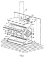
- the stove of Figure 1 is basically made up of two hourglass shaped sections 11 and 12, which are respectively a fire/ash portion and a heat exchanger/flue-outlet portion.
- the double hourglass shape of the stove results in a very high surface area to volume ratio.
- the total surface area is approximately 13 sq. ft. for a total firebox volume of approximately 1 sq. ft..
- the firebox has steel side plates, between 1/8" and 1/4" thickness, the remainder of the firebox being steel of between 1/16" and 1/8" thickness.
- the firebox has an overall height of 24", a width of 18" and a depth of 9". It will be understood that the stove parts can be equally functionally made of cast iron or other suitable materials and by methods well known to those versed in the art.
- the size of the firebox is not essential to its operation and could vary by a factor of between .6 and 2 or more.
- the frontal plane of a portion connecting the two hourglass sections is fitted with a fuel loading door 13 containing a tempered or other suitable glass pane 14 mounted in a gasketed channel around a fuel inlet opening and kept in a closed position by two latch bars 15, interconnected by handle 16.
- the handle 16 allows for single-handed opening of the door 13 and acts also as a guard rail against direct contact with the hot stove by loose clothing etc..
- Latch bars 15 hook behind projections 15a, attached to the side walls 17.
- the necked-down portion 18 of the upper section 12 defines an elongate narrow opening 18a which extends the width of the stove and communicates with an upper chamber or heat exchanger 19 to which is attached at the back flue collar 20 forming a combustion gas outlet and, connecting the firebox by means of flue pipe 21 to a fireplace adaptor plate 22, covering fireplace opening 23 and thus making use of a fireplace chimney (not shown).
- flue pipe 21 could be directly connected into a chimney flue opening by means of either a horizontal or 90 0 elbow or vertical pipe.
- top plate 24 of the firebox can be equipped with a vertically projecting flue collar 25 for direct vertical connection to flue pipe 26 and thence to a suitable chimney. This latter arrangement allows for a closer placement of the stove to a wall of a building. Top plate 24 can be readily used for cooking.
- a control lever 27 is fitted to the back of the heat exchanger 19 and its position is indicated by scale 28. The operation of this stove will be explained below.
- the side walls 17 contain windows 29 covering openings in the side walls 17 and set in gasketed frames 30, the windows 29 being readily removable for replacement purposes. Visible through one of the windows 29 is one of a part of secondary combustion air channels 31. Visible through front window 14 is main rear grate j 32 which, together with a front upper panel 47 of an ash drawer compartment 33, defines the necked-down portion 34 defining an opening 34a similar to the opening 18a. Ash drawer 46 is shown in a closed position inside a lower chamber or compartment 33. The stove is shown equipped with a combination hearth or floor heat-shield/humidifier 36 on a hearth.
- cold outside air is admitted through intake duct 37, through conical collar 39, through damper valve 40 and openings 41 into triangular channel 42, enclosed by back plate 43 and plates 32a and 32b forming parts of the main grate 32, and then over baffle 32c which is integral with main grate 32 and through triangular openings 44 at the ends of plate 32b into ash drawer compartment 33 then through full length opening 34a and grate bars 35b of a grate liner unit 35 supporting fuel 36.
- a portion of this air also flows into gap 34b between firebox liner 35a and firebox front plate 38 and exits through opening 39 near the lower edge of glass pane l4 set in doorframe 13 having a gap 13a around its perimeter containing a glass fibre or asbestos gasket, engaging throat 41 of the stove front when the door 13 is in the upright or closed position and forming a substantially air-tight seal therewith.
- Door 13 is hinged by pins 13c and hinge brackets 13b and 13d respectively attached to door 13 and plate 38.
- Compartment 33 contains ash drawer 46 which is attached to it the secondary grate screen 45.
- Drawer 46 is made up of front plate 46a equipped with sloping upper lip/combination pull-out handle 46b which engages matchingly sloped edges 47a forming a continuation of compartment top front plate 47.
- Drawer front 46a also has a horizontally projecting lip 46c which engages a horizontal extension of stove bottom 48. Front 46a is closely fitted between side plates 17. The foregoing results in an essentially air-tight metal-to-metal seal between drawer and stove.
- Drawer 46 is further made up of sides 46d carrying screen 45 and a bottom 46e equipped with a stiffening rib 46f and a tapered ash entrance lip 46g which, when the unit is inserted into compartment 33, will scrape any ashes left on bottom plate 48 into the drawer interior 46h.
- Ut will be understood that unit 46 has no back. This allows for the aforementioned action-as well as allowing the contents to be emptied without removing screen 45. Combustion of fuel 36 takes place in combustion chamber 49.
- Hot combustion products rise through opening 18a into heat exchanger 19, flowing over all the interior sides of the interior of the combustion chamber 49 and of heat exchanger invluding the underside of stove top plate 24, being forced to travel around full width baffle 50 and diverted by a partial vertical baffle 51 attached to top 24, to the ends of heat exchanger 19 and back over inside of back plate 43c and lower back plate 43b and finally through opening 52 into flue collar 20 and flue pipe 21 connected to the fireplace adaptor plate 22.
- Collar 20 projects partially into heat exchanger 19.
- Baffle 50 is equipped with a small opening 50a directly in line with flue collars 20 and 25, allowing any creosote buildup to run back into the fire.
- a full width baffle 53 is pivotally mounted on pins 54 and is normally held in a horizontal position by a finger 55 attached to the door 13. When door 13 is opened, finger 55 will retract and baffle 53 will assume a vertical position 53a thereby reducing the effective door opening and minimizing the escape of smoke into the room by virtue of a principle well known to those versed in the art.
- plate 32c is arranged to act as a damper to cover openings 44 by pivoting about the apex of plates 32c and 32b.
- a pivot shaft at that point projecting through side wall 17 and fitted with a short crank arm can be connected to door hinge bracket 13b by a simple linkage, so that on opening of door 13, the air intake is shut off, inducing intake flow through the door opening.
- the main grate bars 35b support wood-fuel pieces 36 and keep them from contacting plates 32a and 3 5a, thus allowing combustion air flow freely underneath fuel 36 and providing thorough and lively combustion.
- small pieces 60 will fall through opening 34 onto screen 45, directly into the path of the inrushing preheated combustion air entering through openings 44.
- the proximity of coals 60 to gap 34 and fuel 36 promotes continued combustion by virtue of the radiated and convected heat.
- grates 32 and the liner:35a constitute a self-feeding grate arrangement; as the fuel 36 is consumed, it will rotate and slide by gravity towards centre opening 34, resulting in thorough and lively combustion.
- ash 61 will fall through screen 45 and collect in drawer 46.
- the shape of unit 19 is extremely rigid and resists buckling, this is also eliminated by the very uniform distribution of heat.
- the short baffle 51, attached to the removable top plate 24 further enhances full width flow to the ends of heat exchanger 19.
- the continuous heat exchange between cold combustion air and plates 32a and 35a inhibits the 'burning out' of same and in any case, both can be readily removed for inspection and replacement.
- a small fan or fans 57 ate mounted some distance from back plate 43 on spacer 57a and are equipped with a thermostatic switch 57b carried on bracket 57c capable of switching power through cord 57d to fan 57 when a temperature of between 140 0 and 180 0 F is reached and to shut off power when temperature drops below this range.
- the triangular intake air preheating manifold 42 is defined by plates 32a and 32b and the unit back plate 43 to which the conical intake collar 39 is attached.
- the ends of manifold 42 are defined by the unit end plates 17.
- Plate 32a is the main grate rear plate and is formed in one piece with combustion air distribution plate 32b and baffle 32c which is inclined so as to promote the flow of cold intake air through gap 62, running the full width of the stove, into close contact with underside of plate 32a allowing effecient heat transfer to the combustion air.
- Openings 44 are formed by having the corners cut from the developed plate 32. The formed unit is removable for replacement purposes and rests inside the unit on bars 63 diagonally attached in the rear corners. Placement of the openings 44 is such that the air flow is divided after entering through collar 39 and flows to either end of duct 42, heating up as described above.
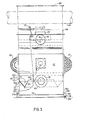
- FIG. 3 Back plate 43 is partially cut away to show the end of the grate 32 and duct 42 arrangement.
- Figure 3 also shows the general arrangement of control unit 27, an add-on heat exchanger 64 covered by the unit's top plate 24 and a forced air connection duct 65 running through the centre of 64 to allow heated air to be conveyed to adjoining rooms or areas of a dwelling.
- Heat exchanger 64 and duct 65 are also shown in Figure 2.
- baffle 66 can be rotated to position 68 to allow a more direct draft to flue pipe 21.
- baffles 50 and 51 and of combination heat shield/humidifier 36 which is essentially a shallow duct or water container of approximately 1" height, as wide as or wider than the depth of unit bottom plate 48, and extending a length equal to or greater than the width of the bottom plate 48 and terminating at both ends in upturned portions 36a having an upwardly open top 36b adjacent the periphery of the lower chamber to allow for refilling by watering can, observation of water level 36c and, of course, exit of water vapour for humidification purposes.
- the evaporative heat required for this helps keep wood floor and floor joists below the unit cool and safe from formation of pyrophoric carbon and its attendant fire hazard.
- Unit 36 is also provided with floor attachment lugs 36d to prevent the stove which is closely fitted between uprights 36a from moving around during fuel loading, poking or accidental bumps.
- Hemispheres 69 are one piece units formed of metal, glass, ceramic or other suitable material with a transition to a square flange equal in size to glass 29. They can be deeply ribbed vertically or richly embossed, as shown on opposite ends, to add additional surface area to promote rapid heat exchange with the room. Their projecting position into the natural convection currents enhances this further.
- FIG. 4a shows the intake damper 40 in detail.
- six sector shaped openings 41 in rear plate 43 are matched by six identical openings 40a in circular plate 40, being rotatably mounted on stud 40b, welded to back 43 and as shown in Figure 4b being held in close contact with washers 40c and 40d, accomodating mounting bracket 39d of intake collar 39, and being held in place by wingnut 40e.
- opening and closing of opening 41 is affected by rotating plate 40 be means of a control rod 81 connected to tab 40f. Openings 41 and 40a are shaped so as to permit accurate control of combustion air flows at the lower end of the control range which will now be explained.
- the sector shaped openings 40a have only one radially oriented edge each. If both edges were so oriented, the upper one of opening 40a would be at 40g. Instead, it is offset by a small distance nearest the center of disc 40 and is located at 40h.
- damper 40 When damper 40 is in the closed position with the tab 40f in the position shown in broken lines at 40i, the blank portion of plate between openings 40a will cover openings 41 f completely.
- the damper control is actuated and control rod 81 moves up a small distance, rotating tab 40f to position 40i'; edge 40h will rotate clockwise across the leading edge of the corresponding hole 41 and open only a small triangular area 40j instead of an area 40k' the full length of radial edge 40g, had it been so constructed.
- Area 40j is only about 1/5 of the area of 40k for the same rotation of plate 40, thus accurate flow control is obtained.
- Intake cone 39 is comprised of tapered collar 39a, a conical transition 39b and flange 39c.
- a bracket 39d, attached to 39a, keeps the unit tightly pressed against back plate 43 by means of wingnut 40b, as previously described.
- a partial radial opening or cut-out 39e of flange 39c allows tab 40f to project through to the outside of intake 39.
- Collar 39a can be readily connected by means of intake duct 38 shown in Figure 2 through fireplace adaptor plate, shown in Figure 1, to a suitable intake grill on the exterior wall of the dwelling.
- Fitting 39 also has two or more fresh air supply ports 39f, closed by bimetal strips 39g attached with rivets 39h.
- the bimetal strip is such as to curve away from holes 39f when a suitable temperature has been reached in the fire chamber of the appliance. Flow will be proportionally compensated by outside air temperature as a equilibrium is reached at any given time. Fresh air entering the room is carried past back of unit by convection currents.
- FIG. 5a and 5c show the general arrangement of heat control by virtue of sensing the heat of combustion in heat exchanger 19 and a mechanism to open or close the combustion air intake damper 40 accordingly.
- a cylindrical fitting 70 is attached in close proximity to both flue collars 20 and 25 and just below cover 24 in the rear plate 43c of heat exchanger 19; both ends of cylinder 70 are open.
- a tube 71 with one closed end, is rotatably mounted through fitting 70 and is securely fastened by any of a number of well known methods to control hub 75. The assembly of 71 and 75 can turn freely in fitting 70.
- Tube 71 contains a helically wound bimetal coil 72, fastened near the closed end of 71 with rivet 71a and is attached at its other end to control shaft 73, rotatably mounted .through hub 75.
- Hub 75 is provided with a handle 27 having at its upper end a knob of Bakelite or similar heat resistant material.
- the entire assembly 71, 72, 73, 74 and 27 is kept in place by bracket 28, shown in Figure 5b, which is mounted by means of two openings 28c, slotted in parallel relationship to tube 71, to matched holes in the upper flange of heat exchanger 19 and cover 24, and having a forked flat spring portion 28a projecting down and at an angle, to press hub 75 - by virtue of pressure on either side of shaft 73 - against fitting 70.
- This arrangement allows for periodic removal and maintainence or tightening of the entire control unit.
- the heat produced by a combustion in the stove will cause the bimetal helix 72 to remain at a given state of helical expansion so long as the fire produces a given amount of heat resulting in a given temperature in heat exchanger 19.
- crank arm 77 is equipped with pivot 78 to which is fitted the upper control rod 79a, held in place by hairpin clip 79b and having a horizontal portion of square cross-section 7 9c fitted in a fusible link 80 to a horizontal portion 81 a of square cross-section, of lower control rod 81 which at its lower end is attached to damper 40 as previously described, and in doing so will rotate the damper shut in accordance with the degree of heating experienced in heat exchanger 19 and thus diminish the supply of combustion air to the fire and thereby reduce the rate of combustion.
- the fire is automatically controlled at the pre-set rate.
- Carying positions of control lever 27 will result in the fire being controlled at correspondingly varying rates.
- Portion 28b of bracket 28 is marked to indicate the range of control.
- the horizontal portion of finger 28a acts as a stop for lever 27 at edge 28d.
- Fusible link 80 is provided in case either coil 72 or shaft 73 seize or otherwise fail to operate, allowing the unit to burn its fuel charge in uncontrolled fashion. In such a case, the vicinity of heat exchanger 19 will rise to such extreme temperatures that fusible link 80 will melt, allowing the weight of rod 81 to cause the damper 40 to rotate shut and thus exclude combustion air from the unit and effectively extinguish the run-away combustion taking place.
- Rod 81 will be kept upright for this purpose by a loose fitting keeper 82 attached to unit rear plate 43.
- FIG. 6a this is a pictorial drawing of the interior of the fire chamber and particularily the main gate 32 and liner assembly 35. Reference may be made to the description pretaining to Figures 2 and 3. Secondary combustion air preheating channels 31 are shown loosely mounted in 'U' brackets 31a attached to end plates 17 and kept in place at the bottom by keeper 31b attached to main grate 32. This allows for ready removal for cleaning. Channel 31 also acts as a guard for the inside of glass 29.
- liner 35 in another embodiment of liner 35 as shown in Figure 6b, provision is made for the use of a refractory cast-in-place lining.
- unit 35 is equipped with somewhat higher grate bars 35d and an expanded metal screen 35e attached between them parallel to liner plate 35c. This allows a castable refractory 39f to be installed to the height shown, being anchored to the whole by screen 35e. Since no liner plate exists on the main grate side of unit 35, a refractory pan 35g is attached to grate bars 35d at that side under a similar screen 35e and thus also suitable to having a refractory material 35f cast in place. A refractory lining would improve the service life of the grate and the liner.
- FIG 7a shows a thermostatic bimetallic grate shaking arrangement.
- Liner plate 35a is equipped with a bimetallic snap-action disc of a type well known to those versed in the art.
- Bimetallic disc 83 is loosely held in annular groove 84 formed from or attached to plate 35a.
- Bracket 85 is attached to the centre of disc 83 and is pivotally connected to grate bar 35b which in turn is pivotally mounted to bracket 86 by means of rivet 87.
- the disc 83 will heat up from the effect of the fire in the grate and snap to a shape shown as 83' and in doing so, snap bar 35b sharply to position 35b'.
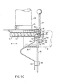
- FIG. 7c and 7d show another type of thermostatic shaking device.
- a continuous bimetallic strip 88 is formed in alternatively concave and convex curved sections 88a and 88b.
- each portion 88a and 88b is formed with some compound curvature 88a" and 88b" in its generally cylindrical shape and thus have a small amount of spherical disc. Disturbance of fuel and ash now takes place only directly over opening 34. This action could be enhanced by placing sharp teeth 90 along the entire top edge of strip 88.
- the shaking element 88 is held in place vertically by slots 89 punched to accomodate the grate bars 35b on which the entire unit 88 can be readily installed or removed since, again, liner 35 is removable.
- FIGS 8a and 8b show a coal burning grate arrangement 91 which may be installed simply by inserting it through the door opening after grate 32 and liner 35 have been removed.
- the generally higher temperatures encountered in the combustion of coal necessitate this unit to be constructed from cast iron or an equivalent material.
- the grate consists of a basket 92 with a sloped bottom plate 93 with, at its lower end, scalloped openings 94 and upturned projections 95 between these openings.
- Movable grate plate 96 consists of plate 97 having scalloped openings 98 in matched relationship with openings 94 and the projections between openings 98 rest on projections 95.
- grate 96 is pivotally mounted by pivot 99 through holes 99a in side plates 114 at one side and by a stub pivot shaft 99c journalled in an upwardly open support 99b at the opposite side and is equipped with square key end 100 and as key 100 will project through a hole in side plate 17 of stove being in matched relationship with hole 99a, grate 96 may be rotated or shaken using a tool well known to those versed in the art, to position 96' and thus agitate and shake the fire or empty the coals into drawer 46. At rest on projections 95, grate 96 is inclined to an angle equal to that of fixed plate 93.
- the basket 92 further comprises front plate 101 and legs 102, which resting on steel grate plate 38, will result in a gap 110 between the sloped and vertical portions of the basket and plate 38.
- Back plate 103 has a projecting ridge 104 which keeps plate 103 in spaced relationshop with stove steel back plate 49.
- a sloped extension 105 over the full width of the unit and a partial width baffle 106 in the area of intake openings 41 define a triangular combustion air preheating duct 107. In operation, combustion air flowing in through openings 41 is preheated and ducted in much the same fashion as previously described in Figures 2 and 3.
Landscapes
- Engineering & Computer Science (AREA)
- Chemical & Material Sciences (AREA)
- Combustion & Propulsion (AREA)
- Mechanical Engineering (AREA)
- General Engineering & Computer Science (AREA)
- Solid-Fuel Combustion (AREA)
Applications Claiming Priority (2)
| Application Number | Priority Date | Filing Date | Title |
|---|---|---|---|
| CA351709 | 1980-05-12 | ||
| CA000351709A CA1148049A (en) | 1980-05-12 | 1980-05-12 | Solid fuel stove |
Publications (2)
| Publication Number | Publication Date |
|---|---|
| EP0040100A1 true EP0040100A1 (de) | 1981-11-18 |
| EP0040100B1 EP0040100B1 (de) | 1984-08-15 |
Family
ID=4116917
Family Applications (1)
| Application Number | Title | Priority Date | Filing Date |
|---|---|---|---|
| EP81302111A Expired EP0040100B1 (de) | 1980-05-12 | 1981-05-12 | Ofen für feste Brennstoffe |
Country Status (4)
| Country | Link |
|---|---|
| US (1) | US4362146A (de) |
| EP (1) | EP0040100B1 (de) |
| CA (1) | CA1148049A (de) |
| DE (1) | DE3165527D1 (de) |
Cited By (9)
| Publication number | Priority date | Publication date | Assignee | Title |
|---|---|---|---|---|
| EP0076585A1 (de) * | 1981-10-05 | 1983-04-13 | Trianco Redfyre Limited | Kohle und Holz verbrennende Öfen |
| FR2527746A1 (fr) * | 1982-06-01 | 1983-12-02 | Vermont Castings | Appareil de chauffage brulant un combustible |
| FR2586088A2 (fr) * | 1985-08-07 | 1987-02-13 | Graziani Adelciso | Recuperateur de chaleur pour economiser l'energie |
| US4683868A (en) * | 1986-04-09 | 1987-08-04 | Vermont Castins, Inc. | Wood burning stove having glass cleaning system |
| US4856491A (en) * | 1988-03-25 | 1989-08-15 | Vermont Castings, Inc. | High efficiency solid fuel burning stove |
| US4865011A (en) * | 1986-06-20 | 1989-09-12 | Vermont Casings, Inc. | Solid fuel burning space heating appliances |
| ITRA20090011A1 (it) * | 2009-03-24 | 2010-09-25 | Malta Ing Michele | Stufa a condensazione |
| EP2388526A3 (de) * | 2006-03-13 | 2012-06-06 | Basic Holdings | Elektrokamin |
| ES2447665A1 (es) * | 2012-09-12 | 2014-03-12 | Universidade De Vigo | Quemador autonómo de biocombustible sólido |
Families Citing this family (28)
| Publication number | Priority date | Publication date | Assignee | Title |
|---|---|---|---|---|
| US4469083A (en) * | 1981-06-05 | 1984-09-04 | Unr Industries, Inc. | Wood burning stove |
| US4580546A (en) * | 1981-10-28 | 1986-04-08 | Condar Co. | Catalytic stove |
| US4556044A (en) * | 1982-06-18 | 1985-12-03 | Barsness Gerald H | Wood and coal burning stove |
| DE3302348A1 (de) * | 1982-12-23 | 1984-06-28 | Karl 6950 Mosbach Flanderka | Feuerstelle |
| US4621610A (en) * | 1985-01-31 | 1986-11-11 | Tomooka Walter K | Solid fuel heating apparatus |
| US4643165A (en) * | 1986-02-26 | 1987-02-17 | Chamberlain Joseph G | Nonpolluting, high efficiency firebox for wood burning stove |
| US5014683A (en) * | 1989-10-27 | 1991-05-14 | Wilkening Donald W | High efficiency fireplace and method of operation |
| US6035812A (en) * | 1998-11-02 | 2000-03-14 | The Water Heater Industry Joint Research And Development Consortium | Combustion air shutoff system for a fuel-fired heating appliance |
| US6267113B1 (en) * | 1999-03-25 | 2001-07-31 | Fire Design Llc | Free standing fireplace hearth |
| DE10015632C1 (de) * | 2000-03-29 | 2001-09-27 | Schott Glas | Sichtscheibe für Raum- oder Etagenheizgeräte |
| US7066170B1 (en) * | 2000-10-31 | 2006-06-27 | Travis Industries, Inc. | Apparatuses and methods for balancing combustion air and exhaust gas for use with a direct-vent heater appliance |
| US6497200B2 (en) | 2001-03-08 | 2002-12-24 | The Water Heater Industry Joint Research And Development Consortium | Fuel-fired heating appliance with combustion chamber temperature-sensing combustion air shutoff system |
| US6715451B2 (en) | 2001-03-08 | 2004-04-06 | The Water Heater Industry Joint Research And Development Consortium | Fuel-fired heating appliance with combustion air shutoff system having frangible temperature sensing structure |
| US6893253B2 (en) * | 2001-03-08 | 2005-05-17 | The Water Heater Industry Joint Research And Development Consortium | Fuel-fired heating appliance with temperature-based fuel shutoff system |
| US7617820B2 (en) * | 2004-06-15 | 2009-11-17 | Smart Parts, Inc. | Pneumatic paintball gun |
| US7325541B2 (en) * | 2004-06-28 | 2008-02-05 | Emmanuel Marcakis | Adjustable primary air supply for wood burning device |
| US7594506B2 (en) * | 2005-09-26 | 2009-09-29 | William Richard Lundberg | Stove with door opening mechanism |
| US20090211565A1 (en) * | 2008-02-27 | 2009-08-27 | Eric Dufour | Fireplace firewood retainer assembly with air deflector, fireplace incorporating the same and method of reducing particulate emissions in a wood burning fireplace |
| US9046273B2 (en) * | 2010-01-11 | 2015-06-02 | Jotul North America, Inc. | Methods for operating a top loading wood-fired appliance having a cooperating top-loading door and movable baffle |
| US8161959B1 (en) | 2010-01-12 | 2012-04-24 | O'reilly Paul D | Wood burning furnace |
| US9803862B2 (en) | 2010-06-04 | 2017-10-31 | Maxitrol Company | Control system and method for a solid fuel combustion appliance |
| US10234139B2 (en) | 2010-06-04 | 2019-03-19 | Maxitrol Company | Control system and method for a solid fuel combustion appliance |
| US11022305B2 (en) | 2010-06-04 | 2021-06-01 | Maxitrol Company | Control system and method for a solid fuel combustion appliance |
| US8783245B2 (en) * | 2010-11-19 | 2014-07-22 | General Electric Company | Ventilation system for a range hood with exhaust and recirculation options |
| WO2013159069A1 (en) * | 2012-04-19 | 2013-10-24 | C. Cretors & Company | Air popcorn popper |
| US9273869B1 (en) | 2013-08-05 | 2016-03-01 | Paul D. O'Reilly | Wood burning furnace |
| US9476593B2 (en) * | 2014-04-22 | 2016-10-25 | Emmanuel Marcakis | Variable secondary air intake device |
| DE102020005202A1 (de) * | 2020-08-25 | 2022-03-03 | Maxitrol GmbH & Co. KG | Einrichtung zur elektronischen Regelung für Kaminöfen mit unterem Abbrand |
Citations (10)
| Publication number | Priority date | Publication date | Assignee | Title |
|---|---|---|---|---|
| DE62201C (de) * | F. RIEGER in Stuttgart, Schlofs. strafse 12 | Heizofen ohne Rost mit Schräg, schachtfeuerung | ||
| US2093897A (en) * | 1936-08-18 | 1937-09-21 | Louise E Burchett | Stove |
| US2250146A (en) * | 1940-04-10 | 1941-07-22 | Otto E Williams | Heater |
| DE889062C (de) * | 1949-01-15 | 1953-09-07 | Hans Schertz | Von senkrechten Strahlungsrippen umgebener einzugiger Eisenmantelofen |
| US2692504A (en) * | 1949-06-02 | 1954-10-26 | Bearl E Colburn | Emergency damper control |
| US2705488A (en) * | 1949-07-07 | 1955-04-05 | Harry T Wright | Fireplace heat exchanger |
| US4036205A (en) * | 1975-05-02 | 1977-07-19 | Hayes-Te Equipment Corporation | Fireplace stove |
| US4163440A (en) * | 1977-05-11 | 1979-08-07 | Suburban Manufacturing Company | Radiant heater |
| US4201185A (en) * | 1978-08-21 | 1980-05-06 | Black Milton W | Method and means for heating by wood burning |
| US4210119A (en) * | 1977-07-07 | 1980-07-01 | Kincaid Duane P | Sheet metal fireplace stove with improved draft |
Family Cites Families (15)
| Publication number | Priority date | Publication date | Assignee | Title |
|---|---|---|---|---|
| US563005A (en) * | 1896-06-30 | Fireplace-heater | ||
| US2675707A (en) * | 1954-04-20 | brown | ||
| US771308A (en) * | 1904-03-19 | 1904-10-04 | Louis Giles Horn | Heating apparatus. |
| US1951265A (en) * | 1932-02-03 | 1934-03-13 | Arthur H Bauman | Furnace grate |
| US2361796A (en) * | 1940-06-17 | 1944-10-31 | Interlake Iron Corp | Grate |
| US2936724A (en) * | 1958-06-04 | 1960-05-17 | John W Bishop | Incinerator construction |
| US3168088A (en) * | 1962-02-28 | 1965-02-02 | Virginia Metalcrafters Inc | Thermostatically controlled heating apparatus |
| US3981292A (en) * | 1975-07-24 | 1976-09-21 | Lilly Industries, Inc. | Heater |
| US4095581A (en) * | 1975-08-14 | 1978-06-20 | Preway Inc. | Fireplace construction |
| US4112913A (en) * | 1977-03-15 | 1978-09-12 | Shimek Ronald J | Free standing heating unit |
| US4140101A (en) * | 1977-07-06 | 1979-02-20 | Glover Tony L | Wood burning stove with forced air heating |
| US4176652A (en) * | 1977-08-19 | 1979-12-04 | Verland V. Berg | Free standing fireplace |
| US4136662A (en) * | 1977-09-26 | 1979-01-30 | Willson Allan C | Wood burning stove |
| US4192286A (en) * | 1977-12-27 | 1980-03-11 | Wormington Garold L | Heat exchanger |
| US4257338A (en) * | 1978-09-21 | 1981-03-24 | Chasek Norman E | Process for improved solid fuel combustion |
-
1980
- 1980-05-12 CA CA000351709A patent/CA1148049A/en not_active Expired
- 1980-07-01 US US06/165,157 patent/US4362146A/en not_active Expired - Lifetime
-
1981
- 1981-05-12 DE DE8181302111T patent/DE3165527D1/de not_active Expired
- 1981-05-12 EP EP81302111A patent/EP0040100B1/de not_active Expired
Patent Citations (10)
| Publication number | Priority date | Publication date | Assignee | Title |
|---|---|---|---|---|
| DE62201C (de) * | F. RIEGER in Stuttgart, Schlofs. strafse 12 | Heizofen ohne Rost mit Schräg, schachtfeuerung | ||
| US2093897A (en) * | 1936-08-18 | 1937-09-21 | Louise E Burchett | Stove |
| US2250146A (en) * | 1940-04-10 | 1941-07-22 | Otto E Williams | Heater |
| DE889062C (de) * | 1949-01-15 | 1953-09-07 | Hans Schertz | Von senkrechten Strahlungsrippen umgebener einzugiger Eisenmantelofen |
| US2692504A (en) * | 1949-06-02 | 1954-10-26 | Bearl E Colburn | Emergency damper control |
| US2705488A (en) * | 1949-07-07 | 1955-04-05 | Harry T Wright | Fireplace heat exchanger |
| US4036205A (en) * | 1975-05-02 | 1977-07-19 | Hayes-Te Equipment Corporation | Fireplace stove |
| US4163440A (en) * | 1977-05-11 | 1979-08-07 | Suburban Manufacturing Company | Radiant heater |
| US4210119A (en) * | 1977-07-07 | 1980-07-01 | Kincaid Duane P | Sheet metal fireplace stove with improved draft |
| US4201185A (en) * | 1978-08-21 | 1980-05-06 | Black Milton W | Method and means for heating by wood burning |
Cited By (14)
| Publication number | Priority date | Publication date | Assignee | Title |
|---|---|---|---|---|
| EP0076585A1 (de) * | 1981-10-05 | 1983-04-13 | Trianco Redfyre Limited | Kohle und Holz verbrennende Öfen |
| FR2527746A1 (fr) * | 1982-06-01 | 1983-12-02 | Vermont Castings | Appareil de chauffage brulant un combustible |
| GB2121162A (en) * | 1982-06-01 | 1983-12-14 | Vermont Castings | Solid fuel stoves |
| US4487195A (en) * | 1982-06-01 | 1984-12-11 | Vermont Castings, Inc. | Fuel burning heating apparatus |
| FR2586088A2 (fr) * | 1985-08-07 | 1987-02-13 | Graziani Adelciso | Recuperateur de chaleur pour economiser l'energie |
| FR2597196A1 (fr) * | 1986-04-09 | 1987-10-16 | Vermont Castings | Poele a combustibles solides notamment poele a bois equipe d'un dispositif de nettoyage des parois transparentes |
| US4683868A (en) * | 1986-04-09 | 1987-08-04 | Vermont Castins, Inc. | Wood burning stove having glass cleaning system |
| DE3711849A1 (de) * | 1986-04-09 | 1987-10-22 | Vermont Castings | Holzofen mit glasreinigungssystem |
| BE1001313A3 (fr) * | 1986-04-09 | 1989-09-26 | Vermont Castings | Appareil de chauffage a combustible solide. |
| US4865011A (en) * | 1986-06-20 | 1989-09-12 | Vermont Casings, Inc. | Solid fuel burning space heating appliances |
| US4856491A (en) * | 1988-03-25 | 1989-08-15 | Vermont Castings, Inc. | High efficiency solid fuel burning stove |
| EP2388526A3 (de) * | 2006-03-13 | 2012-06-06 | Basic Holdings | Elektrokamin |
| ITRA20090011A1 (it) * | 2009-03-24 | 2010-09-25 | Malta Ing Michele | Stufa a condensazione |
| ES2447665A1 (es) * | 2012-09-12 | 2014-03-12 | Universidade De Vigo | Quemador autonómo de biocombustible sólido |
Also Published As
| Publication number | Publication date |
|---|---|
| EP0040100B1 (de) | 1984-08-15 |
| US4362146A (en) | 1982-12-07 |
| CA1148049A (en) | 1983-06-14 |
| DE3165527D1 (en) | 1984-09-20 |
Similar Documents
| Publication | Publication Date | Title |
|---|---|---|
| US4362146A (en) | Solid fuel stove | |
| US4201185A (en) | Method and means for heating by wood burning | |
| US4141336A (en) | Fireplace stove | |
| US4179065A (en) | Circulating air building heating system | |
| US4136662A (en) | Wood burning stove | |
| RU2365824C1 (ru) | Отопительно-варочный камин | |
| US4180051A (en) | Furnace | |
| US4265213A (en) | Free standing stove | |
| EP0571446B1 (de) | Ofen für feste brennstoffe | |
| US4368721A (en) | Woodburning stove | |
| US4708069A (en) | Solid fuel heating appliance | |
| US4385620A (en) | Method and means for heating by wood burning | |
| WO1984002568A1 (en) | Fuel burning stove | |
| US4694817A (en) | Heating stove and method for the combustion of fuels in heating stoves | |
| US4207860A (en) | Wood-coal heating unit | |
| IE53356B1 (en) | Improvements in coal and wood burning stoves | |
| US3174473A (en) | Combined fireplace and barbecue grill | |
| US4386599A (en) | Fireplace stove | |
| US2181624A (en) | Fireplace heater | |
| US4248203A (en) | Wood burning stove | |
| US2749905A (en) | Fireplace hot air furnace | |
| US2559271A (en) | Fireplace with movable reflector | |
| US4263888A (en) | Home heating plant | |
| RU2818956C2 (ru) | Отопительное устройство | |
| US179776A (en) | Improvement in stoves |
Legal Events
| Date | Code | Title | Description |
|---|---|---|---|
| PUAI | Public reference made under article 153(3) epc to a published international application that has entered the european phase |
Free format text: ORIGINAL CODE: 0009012 |
|
| AK | Designated contracting states |
Designated state(s): DE FR GB IT NL SE |
|
| 17P | Request for examination filed |
Effective date: 19811218 |
|
| ITF | It: translation for a ep patent filed | ||
| GRAA | (expected) grant |
Free format text: ORIGINAL CODE: 0009210 |
|
| AK | Designated contracting states |
Designated state(s): DE FR GB IT NL SE |
|
| REF | Corresponds to: |
Ref document number: 3165527 Country of ref document: DE Date of ref document: 19840920 |
|
| ET | Fr: translation filed | ||
| PLBE | No opposition filed within time limit |
Free format text: ORIGINAL CODE: 0009261 |
|
| STAA | Information on the status of an ep patent application or granted ep patent |
Free format text: STATUS: NO OPPOSITION FILED WITHIN TIME LIMIT |
|
| 26N | No opposition filed | ||
| PGFP | Annual fee paid to national office [announced via postgrant information from national office to epo] |
Ref country code: NL Payment date: 19860531 Year of fee payment: 6 |
|
| PG25 | Lapsed in a contracting state [announced via postgrant information from national office to epo] |
Ref country code: SE Effective date: 19870513 |
|
| PG25 | Lapsed in a contracting state [announced via postgrant information from national office to epo] |
Ref country code: NL Effective date: 19871201 |
|
| NLV4 | Nl: lapsed or anulled due to non-payment of the annual fee | ||
| PG25 | Lapsed in a contracting state [announced via postgrant information from national office to epo] |
Ref country code: FR Free format text: LAPSE BECAUSE OF NON-PAYMENT OF DUE FEES Effective date: 19880129 |
|
| PG25 | Lapsed in a contracting state [announced via postgrant information from national office to epo] |
Ref country code: DE Effective date: 19880202 |
|
| GBPC | Gb: european patent ceased through non-payment of renewal fee | ||
| REG | Reference to a national code |
Ref country code: FR Ref legal event code: ST |
|
| PG25 | Lapsed in a contracting state [announced via postgrant information from national office to epo] |
Ref country code: GB Free format text: LAPSE BECAUSE OF NON-PAYMENT OF DUE FEES Effective date: 19881118 |
|
| EUG | Se: european patent has lapsed |
Ref document number: 81302111.0 Effective date: 19880601 |