EP0040101B1 - Spleissen von Kabelverzweigungen oder Kabelenden - Google Patents
Spleissen von Kabelverzweigungen oder Kabelenden Download PDFInfo
- Publication number
- EP0040101B1 EP0040101B1 EP81302114A EP81302114A EP0040101B1 EP 0040101 B1 EP0040101 B1 EP 0040101B1 EP 81302114 A EP81302114 A EP 81302114A EP 81302114 A EP81302114 A EP 81302114A EP 0040101 B1 EP0040101 B1 EP 0040101B1
- Authority
- EP
- European Patent Office
- Prior art keywords
- heat
- metal foil
- cable
- adhesive
- foil member
- Prior art date
- Legal status (The legal status is an assumption and is not a legal conclusion. Google has not performed a legal analysis and makes no representation as to the accuracy of the status listed.)
- Expired
Links
- 239000011888 foil Substances 0.000 claims description 123
- 229910052751 metal Inorganic materials 0.000 claims description 56
- 239000002184 metal Substances 0.000 claims description 56
- 239000000853 adhesive Substances 0.000 claims description 55
- 230000001070 adhesive effect Effects 0.000 claims description 55
- 238000000034 method Methods 0.000 claims description 38
- 239000013521 mastic Substances 0.000 claims description 24
- 239000004831 Hot glue Substances 0.000 claims description 23
- 239000004820 Pressure-sensitive adhesive Substances 0.000 claims description 23
- 238000000576 coating method Methods 0.000 claims description 23
- 239000011248 coating agent Substances 0.000 claims description 22
- 238000011084 recovery Methods 0.000 claims description 20
- 230000004888 barrier function Effects 0.000 claims description 15
- 238000009413 insulation Methods 0.000 claims description 12
- 238000010438 heat treatment Methods 0.000 claims description 10
- 239000005030 aluminium foil Substances 0.000 claims description 8
- 239000000463 material Substances 0.000 claims description 8
- 239000004698 Polyethylene Substances 0.000 claims description 7
- -1 polyethylene Polymers 0.000 claims description 7
- 229920000573 polyethylene Polymers 0.000 claims description 7
- 229920000098 polyolefin Polymers 0.000 claims description 7
- 239000011324 bead Substances 0.000 claims description 6
- 239000000203 mixture Substances 0.000 claims description 6
- 239000012943 hotmelt Substances 0.000 claims description 5
- 238000007373 indentation Methods 0.000 claims description 4
- 229910003460 diamond Inorganic materials 0.000 claims description 3
- 239000010432 diamond Substances 0.000 claims description 3
- 238000004519 manufacturing process Methods 0.000 claims description 3
- 239000004677 Nylon Substances 0.000 claims description 2
- 239000012530 fluid Substances 0.000 claims description 2
- 229920001778 nylon Polymers 0.000 claims description 2
- 239000007787 solid Substances 0.000 claims description 2
- 240000005428 Pistacia lentiscus Species 0.000 description 22
- 239000004411 aluminium Substances 0.000 description 6
- XAGFODPZIPBFFR-UHFFFAOYSA-N aluminium Chemical compound [Al] XAGFODPZIPBFFR-UHFFFAOYSA-N 0.000 description 6
- 229910052782 aluminium Inorganic materials 0.000 description 6
- 239000006260 foam Substances 0.000 description 5
- 238000013021 overheating Methods 0.000 description 4
- 238000007789 sealing Methods 0.000 description 4
- 230000004913 activation Effects 0.000 description 3
- 230000008901 benefit Effects 0.000 description 3
- 230000000694 effects Effects 0.000 description 3
- 239000011810 insulating material Substances 0.000 description 3
- 239000000565 sealant Substances 0.000 description 3
- 239000004821 Contact adhesive Substances 0.000 description 2
- 239000004952 Polyamide Substances 0.000 description 2
- 239000005062 Polybutadiene Substances 0.000 description 2
- 239000004793 Polystyrene Substances 0.000 description 2
- 238000013459 approach Methods 0.000 description 2
- 238000009434 installation Methods 0.000 description 2
- 229920002647 polyamide Polymers 0.000 description 2
- 229920002857 polybutadiene Polymers 0.000 description 2
- 229920002223 polystyrene Polymers 0.000 description 2
- 230000001681 protective effect Effects 0.000 description 2
- 229920002943 EPDM rubber Polymers 0.000 description 1
- 229920003345 Elvax® Polymers 0.000 description 1
- 229920002367 Polyisobutene Polymers 0.000 description 1
- 238000004026 adhesive bonding Methods 0.000 description 1
- 125000003277 amino group Chemical group 0.000 description 1
- 229920005549 butyl rubber Polymers 0.000 description 1
- 230000008859 change Effects 0.000 description 1
- 239000004020 conductor Substances 0.000 description 1
- 238000010276 construction Methods 0.000 description 1
- 238000010924 continuous production Methods 0.000 description 1
- 238000005260 corrosion Methods 0.000 description 1
- 230000007797 corrosion Effects 0.000 description 1
- 229920001971 elastomer Polymers 0.000 description 1
- 238000005538 encapsulation Methods 0.000 description 1
- 230000002708 enhancing effect Effects 0.000 description 1
- BFMKFCLXZSUVPI-UHFFFAOYSA-N ethyl but-3-enoate Chemical compound CCOC(=O)CC=C BFMKFCLXZSUVPI-UHFFFAOYSA-N 0.000 description 1
- 230000001747 exhibiting effect Effects 0.000 description 1
- 239000006261 foam material Substances 0.000 description 1
- 230000004048 modification Effects 0.000 description 1
- 238000012986 modification Methods 0.000 description 1
- 239000004033 plastic Substances 0.000 description 1
- 229920003023 plastic Polymers 0.000 description 1
- 238000003825 pressing Methods 0.000 description 1
- 230000002441 reversible effect Effects 0.000 description 1
- 239000005060 rubber Substances 0.000 description 1
- 238000000926 separation method Methods 0.000 description 1
- 239000000758 substrate Substances 0.000 description 1
- 229920006345 thermoplastic polyamide Polymers 0.000 description 1
- 230000001052 transient effect Effects 0.000 description 1
- XLYOFNOQVPJJNP-UHFFFAOYSA-N water Substances O XLYOFNOQVPJJNP-UHFFFAOYSA-N 0.000 description 1
Images



Classifications
-
- F—MECHANICAL ENGINEERING; LIGHTING; HEATING; WEAPONS; BLASTING
- F16—ENGINEERING ELEMENTS AND UNITS; GENERAL MEASURES FOR PRODUCING AND MAINTAINING EFFECTIVE FUNCTIONING OF MACHINES OR INSTALLATIONS; THERMAL INSULATION IN GENERAL
- F16G—BELTS, CABLES, OR ROPES, PREDOMINANTLY USED FOR DRIVING PURPOSES; CHAINS; FITTINGS PREDOMINANTLY USED THEREFOR
- F16G11/00—Means for fastening cables or ropes to one another or to other objects; Caps or sleeves for fixing on cables or ropes
- F16G11/02—Means for fastening cables or ropes to one another or to other objects; Caps or sleeves for fixing on cables or ropes with parts deformable to grip the cable or cables; Fastening means which engage a sleeve or the like fixed on the cable
-
- H—ELECTRICITY
- H01—ELECTRIC ELEMENTS
- H01R—ELECTRICALLY-CONDUCTIVE CONNECTIONS; STRUCTURAL ASSOCIATIONS OF A PLURALITY OF MUTUALLY-INSULATED ELECTRICAL CONNECTING ELEMENTS; COUPLING DEVICES; CURRENT COLLECTORS
- H01R4/00—Electrically-conductive connections between two or more conductive members in direct contact, i.e. touching one another; Means for effecting or maintaining such contact; Electrically-conductive connections having two or more spaced connecting locations for conductors and using contact members penetrating insulation
- H01R4/70—Insulation of connections
-
- H—ELECTRICITY
- H02—GENERATION; CONVERSION OR DISTRIBUTION OF ELECTRIC POWER
- H02G—INSTALLATION OF ELECTRIC CABLES OR LINES, OR OF COMBINED OPTICAL AND ELECTRIC CABLES OR LINES
- H02G15/00—Cable fittings
- H02G15/08—Cable junctions
- H02G15/18—Cable junctions protected by sleeves, e.g. for communication cable
- H02G15/1806—Heat shrinkable sleeves
- H02G15/1813—Wraparound or slotted sleeves
-
- B—PERFORMING OPERATIONS; TRANSPORTING
- B29—WORKING OF PLASTICS; WORKING OF SUBSTANCES IN A PLASTIC STATE IN GENERAL
- B29C—SHAPING OR JOINING OF PLASTICS; SHAPING OF MATERIAL IN A PLASTIC STATE, NOT OTHERWISE PROVIDED FOR; AFTER-TREATMENT OF THE SHAPED PRODUCTS, e.g. REPAIRING
- B29C61/00—Shaping by liberation of internal stresses; Making preforms having internal stresses; Apparatus therefor
- B29C61/06—Making preforms having internal stresses, e.g. plastic memory
- B29C61/0608—Making preforms having internal stresses, e.g. plastic memory characterised by the configuration or structure of the preforms
- B29C61/0666—Making preforms having internal stresses, e.g. plastic memory characterised by the configuration or structure of the preforms comprising means indicating that the shrinking temperature is reached
-
- Y—GENERAL TAGGING OF NEW TECHNOLOGICAL DEVELOPMENTS; GENERAL TAGGING OF CROSS-SECTIONAL TECHNOLOGIES SPANNING OVER SEVERAL SECTIONS OF THE IPC; TECHNICAL SUBJECTS COVERED BY FORMER USPC CROSS-REFERENCE ART COLLECTIONS [XRACs] AND DIGESTS
- Y10—TECHNICAL SUBJECTS COVERED BY FORMER USPC
- Y10S—TECHNICAL SUBJECTS COVERED BY FORMER USPC CROSS-REFERENCE ART COLLECTIONS [XRACs] AND DIGESTS
- Y10S174/00—Electricity: conductors and insulators
- Y10S174/08—Shrinkable tubes
-
- Y—GENERAL TAGGING OF NEW TECHNOLOGICAL DEVELOPMENTS; GENERAL TAGGING OF CROSS-SECTIONAL TECHNOLOGIES SPANNING OVER SEVERAL SECTIONS OF THE IPC; TECHNICAL SUBJECTS COVERED BY FORMER USPC CROSS-REFERENCE ART COLLECTIONS [XRACs] AND DIGESTS
- Y10—TECHNICAL SUBJECTS COVERED BY FORMER USPC
- Y10S—TECHNICAL SUBJECTS COVERED BY FORMER USPC CROSS-REFERENCE ART COLLECTIONS [XRACs] AND DIGESTS
- Y10S285/00—Pipe joints or couplings
- Y10S285/909—Fluorocarbons and memory plastics
-
- Y—GENERAL TAGGING OF NEW TECHNOLOGICAL DEVELOPMENTS; GENERAL TAGGING OF CROSS-SECTIONAL TECHNOLOGIES SPANNING OVER SEVERAL SECTIONS OF THE IPC; TECHNICAL SUBJECTS COVERED BY FORMER USPC CROSS-REFERENCE ART COLLECTIONS [XRACs] AND DIGESTS
- Y10—TECHNICAL SUBJECTS COVERED BY FORMER USPC
- Y10S—TECHNICAL SUBJECTS COVERED BY FORMER USPC CROSS-REFERENCE ART COLLECTIONS [XRACs] AND DIGESTS
- Y10S428/00—Stock material or miscellaneous articles
- Y10S428/913—Material designed to be responsive to temperature, light, moisture
-
- Y—GENERAL TAGGING OF NEW TECHNOLOGICAL DEVELOPMENTS; GENERAL TAGGING OF CROSS-SECTIONAL TECHNOLOGIES SPANNING OVER SEVERAL SECTIONS OF THE IPC; TECHNICAL SUBJECTS COVERED BY FORMER USPC CROSS-REFERENCE ART COLLECTIONS [XRACs] AND DIGESTS
- Y10—TECHNICAL SUBJECTS COVERED BY FORMER USPC
- Y10T—TECHNICAL SUBJECTS COVERED BY FORMER US CLASSIFICATION
- Y10T403/00—Joints and connections
- Y10T403/48—Shrunk fit
-
- Y—GENERAL TAGGING OF NEW TECHNOLOGICAL DEVELOPMENTS; GENERAL TAGGING OF CROSS-SECTIONAL TECHNOLOGIES SPANNING OVER SEVERAL SECTIONS OF THE IPC; TECHNICAL SUBJECTS COVERED BY FORMER USPC CROSS-REFERENCE ART COLLECTIONS [XRACs] AND DIGESTS
- Y10—TECHNICAL SUBJECTS COVERED BY FORMER USPC
- Y10T—TECHNICAL SUBJECTS COVERED BY FORMER US CLASSIFICATION
- Y10T428/00—Stock material or miscellaneous articles
- Y10T428/13—Hollow or container type article [e.g., tube, vase, etc.]
- Y10T428/1328—Shrinkable or shrunk [e.g., due to heat, solvent, volatile agent, restraint removal, etc.]
Definitions
- This invention relates to a method of making a cable splice, branchout, or termination, to splices, branchouts and terminations themselves.
- the invention is more particularly concerned with cable splices, branchouts, terminations, wherein a heat-recoverable member is heat recovered about one or more cable portions.
- the relevant cable portion(s) especially in smaller cables can become overheated during heat recovery of the heat recoverable member.
- Such overheating is undesirable per se, and can so soften the insulation of insulated cable portions that serious problems can arise owing to the recovering sleeve severely distorting the cable portion or pressing it against hard members such as an adjacent branch-off clip or even the recovering edge of the sleeve itself, with the result that the cable insulation may be partly or completely penetrated.
- This distortion or indentation of the cable insulation is a potential source of electrical failure and can be particularly troublesome where the heat-recoverable member surrounds a plurality of cable portions, one of which may be of substantially smaller diameter than at least one other of the cable portions.
- the present invention provides a method of making a cable splice, branchout, or termination, by heat-recovering a member about one or more cable portions extending out of an end of the member; characterised in that a metal foil member is placed around the one, or one of the portions, or individually around more than one of the cable portions, the metal foil member being: (i) of such stiffness as substantially to prevent radial distortion or indentation of the foil-surrounded cable portion during heat recovery of the heat-recoverable member; (ii) coated with a heat-activatable adhesive and either a pressure-sensitive adhesive or a mastic on at least part of its surface facing the cable portion; and (iii) arranged, when the method is used to heat-recover a member about a single cable, to extend from within the member to a position beyond the end of the member.
- this placing which is preferably by wrapping, of the foil member around at least one of the cable portions individually excludes the known arrangements wherein a metal shell or liner is placed around a plurality of cable portions collectively for the different purpose of providing a smooth profile for the heat-recoverable member to recover onto.
- all the cable portions will generally be insulated, although this is not essential.
- the invention further provides a splice, branchout, or termination.
- a metal foil member suitable for wrapping or otherwise placing around a cable portion in a splice, branchout, or termination which comprises an aluminium sheet of thickness 150-250 microns, coated with a hot melt adhesive and a pressure sensitive adhesive.
- the pressure sensitive adhesive is preferably protected before use by a release layer.
- the aluminium sheet preferably also carries a mastic, and preferably has apertures through which adhesive can pass when heating during recovery of the sleeve.
- the hot melt adhesive and the mastic are preferably at distinct separate locations over the aluminium sheet to facilitate wrapping of the sheet around a cable. Areas of foil having no adhesive can act as hinges.
- the use of discrete portions of adhesive to facilitate wrapping is, however, not always essential, particularly in narrow width tapes of the metal foil.
- the principle of the present invention has the considerable advantages of greatly reducing the bulk of protective material around the foil-surrounded cable portion, and the high thermal conductivity of the metal, in direct contrast to the insulating materials previously tried, has positive advantages in ensuring that an adequate seal can be formed by heat-activatable adhesive between the foil member and the cable portion.
- foils previously used around cables have been of thin, very flexible construction, having a highly radiative surface so as to reflect heat from a heat source used to recover the sleeve.
- the present invention envisages at least a portion of the foil to be inside the sleeve specifically so as to ensure that heat reaches the region between cables, especially the region between a small diameter cable and a large cable, by conduction to effect sealing.
- the present foil member provides a mechanically strong support around the cable for the recovering sleeve.
- metal foil integral tube or half- shells assembled to form a tube could be used, it is preferred to use a metal foil member which can be wrapped around the smaller diameter cable portion.
- the aforementioned adhesive seal could be formed by a heat-activatable adhesive normally carried on the inside surface of the sleeve or other heat recoverable member flowing through suitable apertures in the foil member, but it is preferred to carry the adhesive on the foil member with the adhesive surface facing the cable portion. It has been found that this arrangement enables the total amount of heat-activatable adhesive within the enclosure to be reduced, since less adhesive need be carried by the heat recoverable member when there is no need for any excess to form the bond between the metal member and the cable portion.
- adhesive may be provided with the heat recoverable sleeve, and adhesive may be secured, before recovery, to an inner surface of the sleeve.
- the apertures which may be elongate in a direction transversely to that in which the foil is wrapped around the cable, may be of generally rectangular or diamond shape, and preferably extend to one or both edges of the foil, which itself is advantageously of generally rectangular shape.
- the foil member may be such as to surround the cable once, with its ends in abutment, with a small overlap (of, say, at least 20°), or with a larger overlap (of, say, 360°).
- the heat-activatable adhesive carried by the foil is in discrete portions distributed so as to facilitate wrapping of the foil around the cable portion.
- Parallel beads of the heat-activatable adhesive arranged to extend lengthwise along the cable when the metal foil is wrapped thereon are preferred, but other arrangements of dots or other configurations of adhesive portions could be used.
- Hot melt adhesives such as those described in U.S. Patent Nos. 4,018,733 and 4,181,775, based on polyamides, or ethyl vinyl acetate systems, or mixtures thereof, having good tack at 85-90°C may be suitable for some purposes
- mastics such as systems based on butyl rubber based systems, e.g. polyisobutylene mastics, and EPDM rubber, or EPM based mastics may be suitable for other purposes.
- the mastics while providing excellent moisture sealing characteristics, do not have sufficient resistance to linear movement of the cable, and that hot melt adhesives, while having the greater rigidity to resist such movement, do not maintain an adequate moisture seal.
- An elegantly simple solution to this problem has been devised in a preferred embodiment of the present invention, wherein the metal foil carries hot melt adhesive on one portion of its surface and mastic on another portion of its surface in an arrangement such that the foil can be wrapped around the cable with the hot melt and the mastic at separate locations along the cable.
- the hot melt adhesive preferably having a flow temperature substantially lower than that of the mastic, will tend to act as a dam to prevent gradual flowing out of the mastic, and it is preferred to use a foil having hot melt coated portions on either side of a mastic coated portion, so that it does not matter which way the operator wraps the foil around the cable in practice.
- a particularly preferred hot-melt adhesive for the present purposes is described and claimed in our copending European Patent Application, published number EP-A-0041325.
- This application describes and claims an adhesive composition produced by mixing a thermoplastic polyamide having reactive amine groups attached to the polyamide molecule with a vinyl-terminated rubber.
- a coating of pressure-sensitive adhesive is applied over the heat-activatable adhesive(s) to assist in locating the foil on the cable prior to activation of the heat-activatable adhesive(s).
- the pressure sensitive adhesive may be omitted.
- Suitable pressure-sensitive adhesives include systems based on polystyrene, polybutadiene or elvax with suitable tackifiers, but others may be used according to preference. The quantity and nature of the pressure-sensitive adhesive are preferably chosen so that it is incorporated into the other adhesives upon heat-activation thereof, without detracting from the overall adhesive performance.
- the foil member is preferably coated with polyolefin, preferably polyethylene, to improve corrosion resistance, and provide a uniform surface for adhesive bonding.
- polyolefin preferably polyethylene
- the polyolefin may be flame-brushed or corona treated to improve the adhesion.
- the preferred foil member is aluminium foil of 150 to 250 microns thickness, preferably 200 microns thickness, preferably coated on both sides with a polyethylene layer of 40 to 60 microns thickness, most preferably 50 microns.
- the foil member could be built up from layers of thinner materials, but this would normally be less convenient in practice.
- the heat conductivity of the metal foil is utilised to provide an indication of adequate heating to activate the adhesives or sealants inside the heat recoverable member.
- a temperature indicator preferably a thermochromic coating at least on a portion of the foil which can be arranged to project from the end of the sleeve.
- heat conducted along the foil causes the temperature indicator to indicate when the interior of the heat recoverable member reaches an appropriate temperature.
- thermal insulation may be provided immediately adjacent to the end of the heat recoverable member, preferably on the foil itself, to prevent accidental direct heating of the protruding foil from giving a false indication.
- a heat barrier member can be provided, preferably as part of the metal foil member; in such case the metal foil member could comprise a metal foil and a heat barrier bonded to it.
- the provision of a heat barrier member can be advantageous when cables are subjected to heat as well as to mechanical forces. Small cables having poor heatsink properties will benefit particularly from the provision of a heat barrier member.
- the provision of an insulating member allows air to be used as the insulating medium for very little extra bulk around the cable. This is preferable to the provision of an additional heat sink which can take up too much room. Of the ways in which a heat barrier member can be provided, two are preferred.
- a layer of foam material may be bonded to a metal foil, preferably leaving a pressure-sensitive border around the edge of the foil to help secure the foil to a cable.
- a second embodiment is to use a ribbed tube, through which the cable passes and around which a metal foil is wrapped.
- Figures 1 and 2 show a relatively narrow tape of aluminium foil 1, width 1 cm, having a simple coating of hot melt adhesive.
- the foil is approximately 200 microns in thickness, and the adhesive coating is continuous, since the narrow width of the tape does not necessitate special coating to assist wrapping.
- Figures 3 and 4 show the preferred beaded coating of the hot melt adhesive 2 on the foil 1, (250 mm width), Figure 4 also showing the preferred coating 3 of polyethylene on both surfaces of the foil, and an overlying thin coat of pressure-sensitive adhesive 4 being indicated by dots.
- Figures 6a and 6b show schematically an alternative arrangement of hot melt adhesive 2 and mastic 5 at different locations on the foil, for the aforementioned purposes.
- the aluminium foil 1 is approximately 200 microns in thickness
- the polyethylene coating 3 is approximately 50 microns in thickness
- the coating weight of adhesives is approximately 500-1000 g/m 2 , preferably 300-600 g/m 2 hot melt and 400-700 g/m 2 mastic for the combination of hot melt and mastic, and 15-30 g/m 2 for the pressure sensitive adhesive (if present).
- the aforementioned preferred hot melt adhesive was used, with a polystyrene/polybutadiene based pressure sensitive adhesive.
- the foil is wrapped around the smaller diameter cable portion as shown in Figure 5, with the adhesive beads running along the cable, thus facilitating the wrapping operation, since the foil bends more easily at the places between the adhesive beads.
- the pressure-sensitive adhesive helps to hold the foil in place prior to heat-recovery of the sleeve 6 ( Figure 5) around the smaller cable 7 and larger cable 8.
- the cables 7 and 8 are subjected to compressive forces and the smaller cable 7 tends to be overheated, but is substantially protected from distortion or indentation otherwise caused by the hard edges of branch-off clip 9, or of the sleeve 6, by virtue of the protective foil 1.
- some of the heat load will be absorbed by the foil, thus helping to reduce overheating.
- the heat-activatable adhesive carried by the foil 1 is activated during this heat recovery, and bonds the foil securely to the cable 7, with the mastic 5 (see Figure 6a and 6b) if any, forming a moisture seal and the hot melt adhesive 2 acting as a dam to retain the mastic in place as well as itself adding to the adhesive bond.
- the pressure-sensitive adhesive 4. if present, is absorbed into the hot melt adhesive (and mastic if also present) during this operation without ill effect, but may be omitted where mastic is employed since mastic normally has sufficient tack below its flow temperature.
- Figures 7 and 8 show an advantageous embodiment of the invention in which the metal foil 1 carrying the adhesive or sealant beads 2 carries on its surface remote from the beads a coating 20 of thermochromic indicator composition, which may or may not be reversible: the coating may be protected by thermal insulation 21 as shown in Figure 9.
- thermochromic coatings for the foil and the sleeve may be selected, for example from those described in US Patent No. 3816335, British Patent No. 1511053, and Britsh Patent publication 2038478, the coating for the foil preferably having a lower activation temperature than that for the sleeve.
- the heat-recoverable sleeve may be of any suitable kind.
- Heat-recoverable articles are now widely used in many areas where insulation, sealing and encapsulation are required. Usually these articles recover, on heating, towards an original shape from which they have previously been deformed, but the term "heat-recoverable”, as used herein, also includes an article which, on heating adopts a new configuration, even if it has not been previously deformed.
- such articles comprise a heat-shrinkable sleeve made from a polymeric material exhibiting the property of elastic or plastic memory as described for example, in U.S. Patents 2,027,962; 3,086,242 and 3,957,372.
- the original dimensionally heat-stable form may be a transient form in a continuous process in which, for example, an extruded tube is expanded, whilst hot, to a dimensionally heat-unstable form but, in other applications, a preformed dimensionally heat stable article is deformed to a dimensionally heat unstable form in a separate stage.
- an elastomeric member such as an outer tubular member is held in a stretched state by a second member, such as an inner tubular member, which, upon heating, weakens and thus allows the elastomeric member to recover.
- so-called "wrap-around" sleeves have also been developed. Basically these are heat-recoverable sheets which can be wrapped round the substrate to form a generally tubular shape and which, in general, are provided with fastening means for holding them in the wrapped-up configuration during recovery.
- fastening means are mechanical in nature and comprise, for example, rigid clamps, pins or channel members which co-operate with suitably shaped moulded or extruded protuberances adjacent to the overlapping edges of the heat-recoverable sheet.
- fastening means are described, for example, in U.S. Patent 3,379,218, British Patents 1,155,470, 1,211,988 and 1,346,479, and British Published Patent Application No. 2019120A.
- the sheet may be held in the wrapped-up configuration during recovery by means of an adhesive which may, in some cases, be applied on site. End caps (or sleeves having one end closed) may be used for some applications.
- foil member 40 comprises a sheet 42 of aluminium of 200 microns thickness of grade 99.5% soft that has a series of rectangular apertures 44 therethrough.
- the apertures may have another shape, for example diamond shape, and preferably extend as shown to the edges of the foil 40 to assist wrapping around a cable. To the latter end, the apertures may be elongate in a direction that extends, in use, longitudinally of the cable.
- Each surface of the sheet 42 is coated in polyethylene 46.
- the top or outer surface of the sheet 42 is coated with a hot-melt adhesive 48, and the bottom or inner surface is coated with another hot melt adhesive 50 that is pressure sensitive.
- the pressure sensitive adhesive 50 is protected prior to installation of the foil 40 by a release paper 52.
- the foil 40 is wrapped around a cable, particularly a small diameter cable that is adjacent an appreciably larger cable, either with or without overlapping itself.
- a release paper 52 is first removed and then the foil 40 placed in position around the cable, and enclosed by a heat recoverable sleeve. On recovery of the sleeve, adhesive either from the foil and/or from a coating on the sleeve, flows through the apertures 44 to secure the foil 40 to the cable.
- the foil member thus provides mechanical protection of the heated smaller cable and maintains its integrity, even though it may be softened by the heating required to effect sealing and may be surrounded by hot molten adhesive, on recovery of the sleeve.
- Such protection is particularly desirable when the sleeve material is relatively thick, suitable for encompassing the large diameter cable, and thus exerts an appreciable inwardly- directed force on recovery.
- Figures 13 and 14 show further foil members in which an aluminium sheet 60 receives (Figure 13) discrete portions of hot melt adhesive 62 and is overlaid with a continuous coating 64 of pressure sensitive adhesive, and alternatively receives ( Figures 14) a continuous film 65 of hot melt adhesive that is overlaid with discrete portions 66 of pressure sensitive adhesive.
- a ribbed tube preferably of nylon, is used as a heat barrier member.
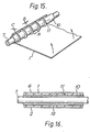
- the tube 10 bears ridges 11 which form pockets of insulating air when an aluminium or other metal sheet 1 is wrapped around the tube 10.
- the cable 7 to be protected passes through the tube 10.
- the dimensions are not critical but the dimension A is preferably about 10 mm, B about 1 mm and C about 1.5 mm.
- a longitudinal cross-section of this arrangement is shown in Figure 16.
- a hot melt adhesive 2 is shown between the metal sheet 1 and an outer heat recoverable sleeve 6.
- Holes 12 are provided through the walls of the tube 10 to allow the passage of adhesive when heat is supplied for recovery of the sleeve 6.
- the size of the hole or holes 12 should be small enough to restrict the flow of heat but large enough to allow passage of sufficient adhesive.
- the distance between the ribs 11 and the thickness of the foil are related since the number of ribs is desirably small to reduce heat conductivity, but one has to ensure that the overlapping metal foil 1 does not collapse between the ribs.
- a separation of 10 mm has been found satisfactory, and we prefer foil of thickness about 200 microns.
- a wraparound version of this heat barrier could be used, comprising a spiral of a poor heat conducting material which would be wound around the cable to be protected. Two thicknesses of metal foil would conveniently be used.
- Figures 17 and 18 illustrate an alternative heat barrier member.
- a foil 1 is coated with a foam 13 and has a border 4 of contact adhesive.
- the border of contact adhesive is used to secure the whole metal foil member to the cable 7 to be protected.
- the metal foil member can be wrapped around the cable 7 as many times as necessary, for example an overlap of 20°, 360° or as many as, say, three times round.
- the foam which is preferably a closed cell, cross-linked polymeric foam, provides the heat insulation required to protect the cable.
- More than one layer of the metal foil member can be provided by ways other than simply wrapping it many times around the cable: for example the foil member could be folded in two and the double thickness wrapped around the cable, giving an insulating layer which has a flattened V-shaped cross-section.
- the foil member could itself be of double thickness, fashioned as a closed bag containing air or some other insulating solid or fluid such as water. These possibilities may be used in addition to or instead of the foam heat barrier layer.
Landscapes
- Engineering & Computer Science (AREA)
- General Engineering & Computer Science (AREA)
- Mechanical Engineering (AREA)
- Cable Accessories (AREA)
Claims (45)
Priority Applications (1)
| Application Number | Priority Date | Filing Date | Title |
|---|---|---|---|
| AT81302114T ATE10246T1 (de) | 1980-05-12 | 1981-05-12 | Spleissen von kabelverzweigungen oder kabelenden. |
Applications Claiming Priority (4)
| Application Number | Priority Date | Filing Date | Title |
|---|---|---|---|
| GB8015697 | 1980-05-12 | ||
| GB8015697 | 1980-05-12 | ||
| GB8038629 | 1980-12-02 | ||
| GB8038629 | 1980-12-02 |
Publications (2)
| Publication Number | Publication Date |
|---|---|
| EP0040101A1 EP0040101A1 (de) | 1981-11-18 |
| EP0040101B1 true EP0040101B1 (de) | 1984-11-07 |
Family
ID=26275490
Family Applications (1)
| Application Number | Title | Priority Date | Filing Date |
|---|---|---|---|
| EP81302114A Expired EP0040101B1 (de) | 1980-05-12 | 1981-05-12 | Spleissen von Kabelverzweigungen oder Kabelenden |
Country Status (5)
| Country | Link |
|---|---|
| US (1) | US4498938A (de) |
| EP (1) | EP0040101B1 (de) |
| CA (1) | CA1165418A (de) |
| DE (1) | DE3167042D1 (de) |
| MY (1) | MY8700762A (de) |
Cited By (2)
| Publication number | Priority date | Publication date | Assignee | Title |
|---|---|---|---|---|
| DE9111996U1 (de) * | 1991-09-26 | 1991-12-05 | Stewing GmbH & Co KG Werk Berlin, 1000 Berlin | Schutzmanschette |
| DE29707622U1 (de) * | 1997-04-26 | 1997-07-03 | Alcatel Alsthom Compagnie Générale d'Electricité, Paris | Vorrichtung zum Schutz des Mantels eines Kabels |
Families Citing this family (24)
| Publication number | Priority date | Publication date | Assignee | Title |
|---|---|---|---|---|
| JPS5985017U (ja) * | 1982-11-29 | 1984-06-08 | 住友電気工業株式会社 | 半割熱収縮スリ−ブの半割部固定工具 |
| GB8322004D0 (en) * | 1983-08-16 | 1983-09-21 | Raychem Ltd | Heat-recoverable article |
| DE3521369A1 (de) * | 1985-06-14 | 1986-12-18 | Walter Rose Gmbh & Co Kg, 5800 Hagen | Vorrichtung als hitzeschutzfolie zum einsatz bei kabeleingaengen in kabelmuffen |
| DE3635204A1 (de) * | 1986-10-16 | 1988-04-21 | Kabelmetal Electro Gmbh | Waermegeschrumpfte umhuellung fuer langgestrecktes gut |
| GB8819354D0 (en) * | 1988-08-15 | 1988-09-14 | Raychem Sa Nv | Re-entry & reclosure of cable splice case |
| GB8904049D0 (en) * | 1989-02-22 | 1989-04-05 | Raychem Sa Nv | Cable splice protection |
| GB8904837D0 (en) * | 1989-03-03 | 1989-04-12 | Robinson Joseph G | Heat shrinkable repair cover for pressurised cables |
| GB8919977D0 (en) * | 1989-09-04 | 1989-10-18 | Raychem Sa Nv | Environmental seal |
| US5958529A (en) * | 1996-11-20 | 1999-09-28 | Raychem Corporation | Side entry sealing device |
| US20030019180A1 (en) * | 1999-11-09 | 2003-01-30 | Warren Peter A. | Foldable member |
| US6374565B1 (en) * | 1999-11-09 | 2002-04-23 | Foster-Miller, Inc. | Foldable member |
| US8074324B2 (en) * | 1999-11-09 | 2011-12-13 | Foster-Miller, Inc. | Flexible, deployment rate damped hinge |
| US6545219B1 (en) * | 2000-04-24 | 2003-04-08 | Tyco Electronics Corporation | Wrap-around cable sleeves having an expandable body portion and methods of making same |
| GB0102976D0 (en) * | 2001-02-07 | 2001-03-21 | Tyco Electronics Raychem Nv | Enclosing device and method |
| EP1806528B1 (de) * | 2006-01-05 | 2008-07-09 | NORMA Germany GmbH | Verbindungsanordnung mit Rohrstutzen zum Verbinden von Fluidaufnahmeteilen |
| US20090184207A1 (en) * | 2008-01-22 | 2009-07-23 | Warren Peter A | Synchronously self deploying boom |
| US8415564B2 (en) * | 2009-11-04 | 2013-04-09 | Tyco Electronics Corporation | Wrap-around cable sleeve assemblies and methods for making and using the same |
| US9402494B1 (en) * | 2014-01-29 | 2016-08-02 | M&S Products, LLC | Closet hanger spacing device and system |
| DE102016108522A1 (de) * | 2016-05-09 | 2017-11-09 | Yazaki Systems Technologies Gmbh | Kabelbaum, Karosserie, Form und Verfahren zur Herstellung des Kabelbaums |
| US11239639B2 (en) | 2016-09-30 | 2022-02-01 | TE Connectivity Services Gmbh | Assembly and method for sealing a bundle of wires |
| EP3566237B1 (de) * | 2017-01-04 | 2022-08-17 | ABB Schweiz AG | Temperaturempfindliche farbwechselnde elektrische vorrichtung |
| EP3565867B1 (de) | 2017-01-04 | 2022-12-14 | ABB Schweiz AG | Thermochrome polymerzusammensetzung, elektrische vorrichtung sowie entsprechende verwendung |
| US10299615B1 (en) * | 2018-07-31 | 2019-05-28 | Stephen P. Donegan | Hanger spacer tape |
| US12144662B2 (en) * | 2023-02-02 | 2024-11-19 | Rashae Deanna Oliver | Surgical instrument organizer |
Family Cites Families (33)
| Publication number | Priority date | Publication date | Assignee | Title |
|---|---|---|---|---|
| US2027962A (en) * | 1933-03-03 | 1936-01-14 | Nat Carbon Co Inc | Production of articles from plastic compositions |
| NL130678C (de) * | 1960-07-15 | 1900-01-01 | ||
| US3379218A (en) * | 1965-07-29 | 1968-04-23 | Raychem Corp | Closure sleeve for pipes or the like |
| US3455336A (en) * | 1965-11-03 | 1969-07-15 | Raychem Corp | Heat recoverable article and process |
| US3451609A (en) * | 1967-08-24 | 1969-06-24 | Us Air Force | Heat shrinkable plastic soldering sleeve |
| US3542077A (en) * | 1968-05-22 | 1970-11-24 | Raychem Corp | Differentially cross-linked article and process for making the same |
| US3541495A (en) * | 1968-08-12 | 1970-11-17 | Raychem Corp | Connector for termination of coaxial cable |
| US3816335A (en) * | 1969-03-24 | 1974-06-11 | Raychem Corp | Reversibly thermochromic ionically and radiation cross-linked polymers containing cobaltous ions |
| US3770556A (en) * | 1970-08-07 | 1973-11-06 | Reychem Corp | Wraparound closure sleeve |
| US3964945A (en) * | 1972-04-07 | 1976-06-22 | E. I. Du Pont De Nemours And Company | Method of making an electrical cable |
| US4035534A (en) * | 1972-09-01 | 1977-07-12 | Raychem Corporation | Heat-shrinkable laminate |
| GB1431167A (en) * | 1972-09-08 | 1976-04-07 | Raychem Sa Nv | Assembly and method for protecitng and insulating a concuit junction |
| US4018733A (en) * | 1972-09-25 | 1977-04-19 | Raychem Corporation | Hot melt adhesive composition comprising an acidic ethylene polymer and a polyamide |
| GB1470049A (en) * | 1973-03-21 | 1977-04-14 | Rachem Corp | Splicing method and heat-recoverable article |
| US3852516A (en) * | 1973-05-02 | 1974-12-03 | C Ploog | Moisture proof splice enclosure for electrical application |
| NL7313698A (nl) * | 1973-10-05 | 1975-04-08 | Chemische Ind Den Haag B V Han | Werkwijze voor het isoleren van verbindingen en luitingen bij elektrische kabels, alsmede e, geschikt voor deze werkwijze. |
| DE2406236C2 (de) * | 1974-02-09 | 1982-05-06 | Kabel- und Metallwerke Gutehoffnungshütte AG, 3000 Hannover | Verbindungselement für koaxiale Paare von Nachrichtenkabeln |
| FR2267358B1 (de) * | 1974-04-11 | 1979-05-25 | Raychem Corp | |
| US4025717A (en) * | 1975-05-07 | 1977-05-24 | Whittingham William F | High voltage shielded cable splice |
| US4181775A (en) * | 1976-05-24 | 1980-01-01 | N.V. Raychem S.A. | Adhesive |
| DE2731578C3 (de) * | 1977-07-13 | 1981-04-16 | Müller, Siegfried, 5800 Hagen | Kabelmuffe mit metallischem Stützmantel und beidseitig an diesen anschließenden Muffenköpfen sowie ein diese Teile miteinander verbindenden Kunststoffschrumfschlauch |
| GB1603658A (en) * | 1977-09-21 | 1981-11-25 | Raychem Corp | Connecting method and connector suitable for coaxial cables |
| NL188254C (nl) * | 1978-01-09 | 1992-05-06 | Raychem Sa Nv | Werkwijze voor het vormen van een afdichting. |
| DE2807154C3 (de) * | 1978-02-20 | 1985-08-01 | Walter Rose Gmbh & Co Kg, 5800 Hagen | Kabelmuffe |
| GB1603880A (en) * | 1978-05-09 | 1981-12-02 | Raychem Pontoise Sa | Electrical connections |
| US4194082A (en) * | 1978-05-24 | 1980-03-18 | Raychem Corporation | Heat recoverable closure with substrate protective means |
| US4226903A (en) * | 1978-08-25 | 1980-10-07 | General Electric Company | Electrical insulating sheet material and electrical winding made therefrom |
| FR2440104A1 (fr) * | 1978-10-27 | 1980-05-23 | Raychem Sa Nv | Raccords thermoretractables notamment pour cables, procede pour leur mise en oeuvre et ensemble les comportant |
| GB2107939B (en) * | 1978-10-27 | 1983-09-01 | Raychem Sa Nv | Heat-recoverable articles |
| GB2038478B (en) * | 1978-12-22 | 1983-09-28 | Raychem Sa Nv | Thermochromic composition |
| CA1152591A (en) * | 1979-08-07 | 1983-08-23 | Jean-Marie E. Nolf | Cable sleeve outlet for splice case |
| GB2075990B (en) * | 1980-05-12 | 1985-05-09 | Raychem Sa Nv | Hot melt adhesive compositions |
| US4345109A (en) * | 1980-11-03 | 1982-08-17 | Pirelli Cable Corporation | Restraint apparatus for pipe type electric cables |
-
1981
- 1981-05-11 CA CA000377280A patent/CA1165418A/en not_active Expired
- 1981-05-12 DE DE8181302114T patent/DE3167042D1/de not_active Expired
- 1981-05-12 EP EP81302114A patent/EP0040101B1/de not_active Expired
-
1983
- 1983-11-02 US US06/549,002 patent/US4498938A/en not_active Expired - Lifetime
-
1987
- 1987-12-30 MY MY762/87A patent/MY8700762A/xx unknown
Cited By (2)
| Publication number | Priority date | Publication date | Assignee | Title |
|---|---|---|---|---|
| DE9111996U1 (de) * | 1991-09-26 | 1991-12-05 | Stewing GmbH & Co KG Werk Berlin, 1000 Berlin | Schutzmanschette |
| DE29707622U1 (de) * | 1997-04-26 | 1997-07-03 | Alcatel Alsthom Compagnie Générale d'Electricité, Paris | Vorrichtung zum Schutz des Mantels eines Kabels |
Also Published As
| Publication number | Publication date |
|---|---|
| US4498938A (en) | 1985-02-12 |
| DE3167042D1 (en) | 1984-12-13 |
| CA1165418A (en) | 1984-04-10 |
| MY8700762A (en) | 1987-12-31 |
| EP0040101A1 (de) | 1981-11-18 |
Similar Documents
| Publication | Publication Date | Title |
|---|---|---|
| US4498938A (en) | Splicing, branching or terminating cable | |
| US4200676A (en) | Method for joining heat-recoverable sheet material and resulting article | |
| US4532168A (en) | Heat shrinkable covering | |
| US5302428A (en) | Multi-layer wraparound heat shrink sleeve | |
| EP0034042B1 (de) | Schrumpfbarer Umhüllungsaufbau | |
| US4466846A (en) | Method of using heat-recoverable articles to produce a pressurizable casing around a substrate | |
| HK20582A (en) | Clip | |
| US4448824A (en) | Wraparound protective closure | |
| CA1286869C (en) | Heat recoverable article | |
| US4359502A (en) | Method for joining heat-recoverable sheet material and resulting article | |
| CA1168934A (en) | Device for enclosing objects | |
| EP0119018B1 (de) | Wärmezurückgewinnender Gegenstand | |
| JPS6034830A (ja) | 熱回復性密閉物品 | |
| CA1195742A (en) | Wraparound closure for electrical conductor | |
| JPH02223321A (ja) | 再封入再包囲方法 | |
| CA1167540A (en) | Heat recoverable closure assembly | |
| EP0196767B1 (de) | Unter Druck stehendes Spleissgehäuse | |
| GB2075771A (en) | Splicing branching or terminating cables | |
| GB2135139A (en) | Heat recoverable article | |
| JPH0258846B2 (de) | ||
| CA2114288C (en) | Multi-layer wraparound heat shrink sleeve | |
| EP0041389B1 (de) | Umwickelte wärmeschrumpfbare Muffen | |
| JPS60167612A (ja) | 圧力保持包囲体の形成方法およびアツセンブリ | |
| CA1206427A (en) | Heat shrinkable covering | |
| AU640380B2 (en) | Environmental sealing |
Legal Events
| Date | Code | Title | Description |
|---|---|---|---|
| PUAI | Public reference made under article 153(3) epc to a published international application that has entered the european phase |
Free format text: ORIGINAL CODE: 0009012 |
|
| 17P | Request for examination filed |
Effective date: 19810526 |
|
| AK | Designated contracting states |
Designated state(s): AT BE CH DE FR IT LI NL SE |
|
| ITF | It: translation for a ep patent filed | ||
| GRAA | (expected) grant |
Free format text: ORIGINAL CODE: 0009210 |
|
| AK | Designated contracting states |
Designated state(s): AT BE CH DE FR IT LI NL SE |
|
| REF | Corresponds to: |
Ref document number: 10246 Country of ref document: AT Date of ref document: 19841115 Kind code of ref document: T |
|
| REF | Corresponds to: |
Ref document number: 3167042 Country of ref document: DE Date of ref document: 19841213 |
|
| ET | Fr: translation filed | ||
| PLBE | No opposition filed within time limit |
Free format text: ORIGINAL CODE: 0009261 |
|
| STAA | Information on the status of an ep patent application or granted ep patent |
Free format text: STATUS: NO OPPOSITION FILED WITHIN TIME LIMIT |
|
| 26N | No opposition filed | ||
| ITTA | It: last paid annual fee | ||
| PGFP | Annual fee paid to national office [announced via postgrant information from national office to epo] |
Ref country code: AT Payment date: 19920512 Year of fee payment: 12 |
|
| PGFP | Annual fee paid to national office [announced via postgrant information from national office to epo] |
Ref country code: SE Payment date: 19920521 Year of fee payment: 12 |
|
| PGFP | Annual fee paid to national office [announced via postgrant information from national office to epo] |
Ref country code: NL Payment date: 19920531 Year of fee payment: 12 |
|
| PGFP | Annual fee paid to national office [announced via postgrant information from national office to epo] |
Ref country code: BE Payment date: 19920604 Year of fee payment: 12 |
|
| PG25 | Lapsed in a contracting state [announced via postgrant information from national office to epo] |
Ref country code: AT Effective date: 19930512 |
|
| PG25 | Lapsed in a contracting state [announced via postgrant information from national office to epo] |
Ref country code: SE Effective date: 19930513 |
|
| PG25 | Lapsed in a contracting state [announced via postgrant information from national office to epo] |
Ref country code: BE Effective date: 19930531 |
|
| BERE | Be: lapsed |
Owner name: N.V. RAYCHEM S.A. Effective date: 19930531 |
|
| PG25 | Lapsed in a contracting state [announced via postgrant information from national office to epo] |
Ref country code: NL Effective date: 19931201 |
|
| NLV4 | Nl: lapsed or anulled due to non-payment of the annual fee | ||
| EUG | Se: european patent has lapsed |
Ref document number: 81302114.4 Effective date: 19931210 |
|
| PGFP | Annual fee paid to national office [announced via postgrant information from national office to epo] |
Ref country code: DE Payment date: 20000508 Year of fee payment: 20 |
|
| PGFP | Annual fee paid to national office [announced via postgrant information from national office to epo] |
Ref country code: FR Payment date: 20000510 Year of fee payment: 20 |
|
| PGFP | Annual fee paid to national office [announced via postgrant information from national office to epo] |
Ref country code: CH Payment date: 20000512 Year of fee payment: 20 |
|
| PG25 | Lapsed in a contracting state [announced via postgrant information from national office to epo] |
Ref country code: LI Free format text: LAPSE BECAUSE OF EXPIRATION OF PROTECTION Effective date: 20010511 Ref country code: CH Free format text: LAPSE BECAUSE OF EXPIRATION OF PROTECTION Effective date: 20010511 |
|
| REG | Reference to a national code |
Ref country code: CH Ref legal event code: PL |