EP0040352B1 - Vorrichtung zum Abgeben von Metallmengen - Google Patents
Vorrichtung zum Abgeben von Metallmengen Download PDFInfo
- Publication number
- EP0040352B1 EP0040352B1 EP19810103405 EP81103405A EP0040352B1 EP 0040352 B1 EP0040352 B1 EP 0040352B1 EP 19810103405 EP19810103405 EP 19810103405 EP 81103405 A EP81103405 A EP 81103405A EP 0040352 B1 EP0040352 B1 EP 0040352B1
- Authority
- EP
- European Patent Office
- Prior art keywords
- molten metal
- tank
- pressure
- gas
- air
- Prior art date
- Legal status (The legal status is an assumption and is not a legal conclusion. Google has not performed a legal analysis and makes no representation as to the accuracy of the status listed.)
- Expired
Links
Images
Classifications
-
- B—PERFORMING OPERATIONS; TRANSPORTING
- B22—CASTING; POWDER METALLURGY
- B22D—CASTING OF METALS; CASTING OF OTHER SUBSTANCES BY THE SAME PROCESSES OR DEVICES
- B22D39/00—Equipment for supplying molten metal in rations
- B22D39/06—Equipment for supplying molten metal in rations having means for controlling the amount of molten metal by controlling the pressure above the molten metal
-
- B—PERFORMING OPERATIONS; TRANSPORTING
- B22—CASTING; POWDER METALLURGY
- B22D—CASTING OF METALS; CASTING OF OTHER SUBSTANCES BY THE SAME PROCESSES OR DEVICES
- B22D18/00—Pressure casting; Vacuum casting
- B22D18/04—Low pressure casting, i.e. making use of pressures up to a few bars to fill the mould
Definitions
- This invention relates to an apparatus for dispensing molten metal into a mold or the like. It includes a molten metal storage container, and a pouring passage extending upwardly from the bottom of the storage container and having an outlet in a position above the highest level of molten metal in the storage container. Compressed gas is introduced into a closed hollow space in the storage container to apply pressure to molten metal therein to discharge it through the outlet of the pouring passage.
- a dispensing system of this type as further defined in the precharacterising part of claim 1 is described in the DE-A-2624435.
- Another known system as described in DE-A-2433060 employs air as a gas for compressing molten metal. When it is desired to discontinue dispensation of molten metal, the compressed air in the storage container is released into the atmosphere. If it is desired to dispense molten metal again, it is necessary to introduce a fresh supply of compressed air into the storage container. If fresh air is introduced into the storage container whenever it is desired to dispense molten metal, however, the storage container always remains filled with a gas containing a large quantity of oxygen.
- This gas oxidizes the molten metal contacting it, and disadvantageously brings about generation of a large quantity of slag, and the loss of effective constituents from molten metal.
- the apparatus is, therefore, unsuitable for use in the dispensation of easily oxidizable molten metal, or molten metal containing an easily oxidizable constituent, though it can relatively easily and accurately control the amount to be dispensed.
- Attempts have, therefore, been made to introduce compressed argon or other inert gas into the storage container in order to prevent such oxidation.
- such an inert gas is expensive, and disadvantageously increases the cost of operation, as it requires a large quantity of such gas.
- a molten metal dispensing apparatus including a molten metal storage container and a pouring passage extending upwardly from the bottom of said container to a point above the highest level of molten metal in said container, and adapted for dispensing molten metal through said pouring passage when compressed air is introduced into a closed hollow space above said molten metal in said container to apply pressure to said molten metal, a high pressure tank in which said compressed air is stored before it is introduced into said storage container, a low pressure tank into which said compressed air is recovered from said storage container, and a compressor for compressing said air from said low pressure tank and returning it into said high pressure tank, whereby a substantially constant negative pressure is maintained in said low pressure tank, and that a pressure regulator is connected between a suction valve and the low pressure tank, said suction valve being vented to the atmosphere or open air.
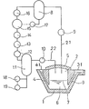
- the system comprises a storage container 1 lined with refractories.
- the storage container 1 defines a storage chamber 2 for storing molten metal 6 therein, and is provided with a pouring passage 3 extending upwardly from the bottom of the storage chamber 2 and having an outlet 31 at a point above the highest level 7 of molten metal 6, and a receiving passage 4 extending upwardly from the bottom of the storage chamber 2 and having an inlet 41 at a higher level than the outlet 31 of the pouring passage 3.
- Molten metal is received through the receiving passage 4, and stored in the storage chamber 2.
- the top opening of the storage chamber 2 is closed by a cover 5 in a gastight manner, so that a closed hollow space may be formed above the molten metal in the storage chamber 2.
- a gas feed line 21 and an exhaust line 22 extend through the cover 5 into the storage chamber 2.
- the gas feed line 21 is connected to a high pressure gas tank 8, in which compressed gas is stored, through a device 9 for controlling the pressure of the gas to be introduced into the storage chamber 2.
- the exhaust line 22 is connected through an exhaust valve 10 to a low pressure gas tank 11 into which exhaust gas is collected.
- the low pressure gas tank 11 has an outlet connected to the inlet of a gas compressor 15 through a primary cooler 12, a drain separator 13 and a filter 14.
- the gas compressor 15 has an outlet connected to the high pressure gas tank 8 through a secondary cooler 16.
- a pressure regulator 17 is provided for detecting the pressure of the gas in the high pressure gas tank 8, and maintaining it at a predetermined level of say, 3.5 kg/cm 2 by causing the operation of the compressor 15 to be stopped if the gas pressure exceeds the predetermined level, while causing it to be started again if the gas pressure has dropped below the predetermined level.
- a suction valve 19 is connected to the low pressure gas tank 11 for drawing air thereinto.
- a pressure regulator 18 is connected between the suction valve 19 and the low pressure gas tank 11 for detecting the pressure of the gas in the tank 11 and maintaining it at a substantially equal negative pressure of, say, -0.3 kg/cm 2 by causing the valve 19 to open if the gas pressure in the tank 11 has dropped below the aforesaid level, while causing it to be closed if the gas pressure exceeds the aforesaid level.
- the compressor 15 In preparation for the pouring operation, the compressor 15 is started for drawing air from the low pressure gas tank 11, and compressing it, so that the compressed air may be stored in the high pressure gas tank 8.
- the pressure regulator 9 and the exhaust valve 10 remain closed. Until the pressure of the gas in the high pressure gas tank 8 reaches a predetermined level of, say, 3.5 kg/cm 2 , the compressor 15 continues in operation, and draws air from the low pressure gas tank 11. Therefore, a gradual reduction takes place in the quantity and pressure of the air in the tank 11. If the pressure of the air in the tank 11 drops below a predetermined level of, say -0.3 kg/cm 2 , the pressure regulator 18 causes the suction valve 19 to open, and draw a fresh supply of air into the tank 11.
- the compressor 15 stops its operation when the high pressure gas tank 8 has been filled with air to the extent that its pressure reaches a predetermined level of, say, 3.5 kg/cm 2 whereupon the apparatus is ready for the dispensing operation.
- the pressure of the air in the low pressure gas tank 11 is maintained at a predetermined negative pressure of -0.3 kg/cm z.
- the pressure regulator 9 is controlled to introduce compressed air from the high pressure gas tank 8 into the closed storage chamber 2 through the feed line 21 for raising the pressure of the gas in the storage chamber 2, whereby pressure is applied to the molten metal 6.
- the level 7 of the molten metal in the storage chamber 2 is lowered, and the levels of the molten metal in the pouring passage 3 and the receiving passage 4 are raised correspondingly. If the molten metal in the pouring passage 3 reaches its outlet 31, it is forced out therethrough into a mold not shown, or the like.
- the pressure regulator 9 continues to introduce compressed air into the storage chamber 2 to maintain therein the pressure required for forcing molten metal out of the pouring passage 3.
- the pressure regulator 9 When it is desired to discontinue the pouring operation, the pressure regulator 9 is actuated in such a manner as to interrupt the supply of compressed air from the high pressure gas tank 8, and the exhaust valve 10 is opened.
- the high pressure air in the storage chamber 2 is drawn into the low pressure gas tank 11 in which a negative pressure is maintained, and reduces its pressure.
- the air in the storage chamber 2 ceases to apply pressure to the molten metal 6 therein, and its level 7 rises, while the level of the molten metal in the pouring passage 3 drops below its outlet 31, whereby the pouring operation is terminated.
- the exhaust valve 10 Upon termination of the pouring operation, the exhaust valve 10 is closed again, so that the apparatus may be ready for another cycle of pouring operation.
- the aforesaid sequences of operation are repeated for dispensing molten metal, and discontinuing any such dispensation.
- the quantity of the molten metal to be dispensed can be controlled by the pressure regulator 9 which controls the duration of pressure application into the storage chamber 2.
- the compressed gas supplied from the high pressure gas tank 8 into the storage chamber 2 is never released into the open atmosphere, but is recovered into the low pressure gas tank 11, so that it may be compressed by the compressor 15 again, and recycled into the high pressure gas tank 8.
- the gas is circulated along a closed loop.
- the closed loop circulation of the gas provides a number of advantages. Oxygen, which is present in a large quantity in the air during the initial stage of operation, is gradually reduced by reacting with molten metal in the storage container 1 during its recirculation in the closed loop. Accordingly, the oxidation of the molten metal 6 in the storage container 1 can be effectively prevented.
- the pressure of the gas in the low pressure gas tank 11 drops below a predetermined level.
- the pressure regulator 18 detects any such pressure drop in the tank 11, and causes the suction valve 19 to open to draw air therethrough to supply a satisfactory amount of additional air into the tank 11.
- the amount of any such additional air is very small, and does not bring about any appreciable increase in the quantity of oxygen in the closed loop.
- the primary cooler 12 provided on the inlet side of the compressor 15 cools the gas from the low pressure gas tank 11 before its transfer into the compressor 15 to thereby protect the compressor 1 against overheating, since the gas recovered from the storage container 1 remains hot due to the high temperature of the molten metal therein.
- the secondary cooler 16 provided on the outlet side of the compressor 15 cools the gas heated during its compression.
Landscapes
- Engineering & Computer Science (AREA)
- Mechanical Engineering (AREA)
- Casting Support Devices, Ladles, And Melt Control Thereby (AREA)
Claims (2)
Applications Claiming Priority (2)
| Application Number | Priority Date | Filing Date | Title |
|---|---|---|---|
| JP6376780A JPS6021819B2 (ja) | 1980-05-14 | 1980-05-14 | 注湯炉 |
| JP63767/80 | 1980-05-14 |
Publications (2)
| Publication Number | Publication Date |
|---|---|
| EP0040352A1 EP0040352A1 (de) | 1981-11-25 |
| EP0040352B1 true EP0040352B1 (de) | 1984-02-08 |
Family
ID=13238849
Family Applications (1)
| Application Number | Title | Priority Date | Filing Date |
|---|---|---|---|
| EP19810103405 Expired EP0040352B1 (de) | 1980-05-14 | 1981-05-06 | Vorrichtung zum Abgeben von Metallmengen |
Country Status (3)
| Country | Link |
|---|---|
| EP (1) | EP0040352B1 (de) |
| JP (1) | JPS6021819B2 (de) |
| DE (1) | DE3162162D1 (de) |
Families Citing this family (3)
| Publication number | Priority date | Publication date | Assignee | Title |
|---|---|---|---|---|
| US4444377A (en) * | 1982-07-14 | 1984-04-24 | Daniel E. Groteke | Molten metal transfer crucible |
| JPS6334564U (de) * | 1986-08-20 | 1988-03-05 | ||
| SE470179B (sv) * | 1992-02-20 | 1993-11-29 | Metpump Ab | Pumpanordning för pumpning av smält metall |
Family Cites Families (2)
| Publication number | Priority date | Publication date | Assignee | Title |
|---|---|---|---|---|
| DE2624435B2 (de) * | 1976-06-01 | 1981-03-26 | Brown, Boveri & Cie Ag, 6800 Mannheim | Verfahren zum dosierten Vergießen schelzflüssiger Metalle |
| CH646624A5 (en) * | 1980-03-13 | 1984-12-14 | Fischer Ag Georg | Process for casting molten metal under the pressure of a protective gas and apparatus for carrying out the process |
-
1980
- 1980-05-14 JP JP6376780A patent/JPS6021819B2/ja not_active Expired
-
1981
- 1981-05-06 DE DE8181103405T patent/DE3162162D1/de not_active Expired
- 1981-05-06 EP EP19810103405 patent/EP0040352B1/de not_active Expired
Also Published As
| Publication number | Publication date |
|---|---|
| EP0040352A1 (de) | 1981-11-25 |
| JPS6021819B2 (ja) | 1985-05-29 |
| DE3162162D1 (en) | 1984-03-15 |
| JPS56160867A (en) | 1981-12-10 |
Similar Documents
| Publication | Publication Date | Title |
|---|---|---|
| US4363222A (en) | Environmental protection refrigerant disposal and charging system | |
| US4261178A (en) | Environmental protection refrigeration disposal and charging system | |
| US4659346A (en) | Device for preventing fuel vapor from escaping to the outside air from a fuel tank | |
| US20150140184A1 (en) | Method And Apparatus For Accelerated Or Controlled Degassing Of Roasted Coffee | |
| US4793596A (en) | Apparatus for and a method of rapidly discharging a molten metal from its supply system of a pressurized holding furnace | |
| EP0040352A1 (de) | Vorrichtung zum Abgeben von Metallmengen | |
| JPS6329117B2 (de) | ||
| US4860804A (en) | Filled amount control system | |
| US5056692A (en) | Dispensing apparatus for molten metal | |
| US4067807A (en) | Process and apparatus for the operation of a filter press having a pressure tank communicating therewith | |
| CA2062954A1 (en) | Float valve for container-filling systems, in particular systems for filling electric drive batteries | |
| AU3682097A (en) | Valve apparatus | |
| JPH03198192A (ja) | 自動販売機内に缶入り飲料を送り込むための装填器 | |
| US3921859A (en) | Siphon for molten metals with suction actuator | |
| JP2869042B2 (ja) | 液状またはペースト状の生成物を貯蔵し、その所定量を分配する装置 | |
| JP2703431B2 (ja) | ナトリウム−硫黄電池における消火装置 | |
| ZA200600074B (en) | System for supplying molten metal, container and a vehicle | |
| JPS6458695A (en) | Drink dispenser | |
| US3229337A (en) | Furnace ladling apparatus | |
| KR102288731B1 (ko) | 수처리 장치 | |
| KR0168556B1 (ko) | 다이캐스트용 용탕 주입장치 | |
| JPH03106399A (ja) | コードレススチームアイロン | |
| US5358027A (en) | Vacuum-assisted gravity pour casting apparatus | |
| JPH09126394A (ja) | 低温液化ガス貯蔵設備 | |
| US4848603A (en) | Holding furnace of constant molten metal level |
Legal Events
| Date | Code | Title | Description |
|---|---|---|---|
| PUAI | Public reference made under article 153(3) epc to a published international application that has entered the european phase |
Free format text: ORIGINAL CODE: 0009012 |
|
| 17P | Request for examination filed |
Effective date: 19810910 |
|
| AK | Designated contracting states |
Designated state(s): DE FR GB IT SE |
|
| ITF | It: translation for a ep patent filed | ||
| GRAA | (expected) grant |
Free format text: ORIGINAL CODE: 0009210 |
|
| AK | Designated contracting states |
Designated state(s): DE FR GB IT SE |
|
| REF | Corresponds to: |
Ref document number: 3162162 Country of ref document: DE Date of ref document: 19840315 |
|
| ET | Fr: translation filed | ||
| PLBE | No opposition filed within time limit |
Free format text: ORIGINAL CODE: 0009261 |
|
| STAA | Information on the status of an ep patent application or granted ep patent |
Free format text: STATUS: NO OPPOSITION FILED WITHIN TIME LIMIT |
|
| 26N | No opposition filed | ||
| PGFP | Annual fee paid to national office [announced via postgrant information from national office to epo] |
Ref country code: FR Payment date: 19900404 Year of fee payment: 10 |
|
| PGFP | Annual fee paid to national office [announced via postgrant information from national office to epo] |
Ref country code: GB Payment date: 19900430 Year of fee payment: 10 |
|
| PGFP | Annual fee paid to national office [announced via postgrant information from national office to epo] |
Ref country code: SE Payment date: 19900504 Year of fee payment: 10 |
|
| ITTA | It: last paid annual fee | ||
| PG25 | Lapsed in a contracting state [announced via postgrant information from national office to epo] |
Ref country code: GB Effective date: 19910506 |
|
| PG25 | Lapsed in a contracting state [announced via postgrant information from national office to epo] |
Ref country code: SE Effective date: 19910507 |
|
| GBPC | Gb: european patent ceased through non-payment of renewal fee | ||
| PG25 | Lapsed in a contracting state [announced via postgrant information from national office to epo] |
Ref country code: FR Effective date: 19920131 |
|
| REG | Reference to a national code |
Ref country code: FR Ref legal event code: ST |
|
| PGFP | Annual fee paid to national office [announced via postgrant information from national office to epo] |
Ref country code: DE Payment date: 19940511 Year of fee payment: 14 |
|
| EUG | Se: european patent has lapsed |
Ref document number: 81103405.7 Effective date: 19911209 |
|
| PG25 | Lapsed in a contracting state [announced via postgrant information from national office to epo] |
Ref country code: DE Effective date: 19960201 |