EP0040410A2 - Universal-Zerspanungsmaschine - Google Patents
Universal-Zerspanungsmaschine Download PDFInfo
- Publication number
- EP0040410A2 EP0040410A2 EP81103728A EP81103728A EP0040410A2 EP 0040410 A2 EP0040410 A2 EP 0040410A2 EP 81103728 A EP81103728 A EP 81103728A EP 81103728 A EP81103728 A EP 81103728A EP 0040410 A2 EP0040410 A2 EP 0040410A2
- Authority
- EP
- European Patent Office
- Prior art keywords
- groove
- universal
- flaking
- flakes
- cylinder
- Prior art date
- Legal status (The legal status is an assumption and is not a legal conclusion. Google has not performed a legal analysis and makes no representation as to the accuracy of the status listed.)
- Withdrawn
Links
- 239000000463 material Substances 0.000 description 12
- 239000002023 wood Substances 0.000 description 4
- 230000000903 blocking effect Effects 0.000 description 3
- 238000009434 installation Methods 0.000 description 2
- 238000004519 manufacturing process Methods 0.000 description 2
- 238000009966 trimming Methods 0.000 description 2
- 229910000831 Steel Inorganic materials 0.000 description 1
- 238000001035 drying Methods 0.000 description 1
- 230000000694 effects Effects 0.000 description 1
- 238000003801 milling Methods 0.000 description 1
- 239000010959 steel Substances 0.000 description 1
- 238000006467 substitution reaction Methods 0.000 description 1
- 230000009466 transformation Effects 0.000 description 1
- 239000002699 waste material Substances 0.000 description 1
Images

Classifications
-
- B—PERFORMING OPERATIONS; TRANSPORTING
- B27—WORKING OR PRESERVING WOOD OR SIMILAR MATERIAL; NAILING OR STAPLING MACHINES IN GENERAL
- B27L—REMOVING BARK OR VESTIGES OF BRANCHES; SPLITTING WOOD; MANUFACTURE OF VENEER, WOODEN STICKS, WOOD SHAVINGS, WOOD FIBRES OR WOOD POWDER
- B27L11/00—Manufacture of wood shavings, chips, powder, or the like; Tools therefor
- B27L11/005—Tools therefor
Definitions
- the present invention relates to a universal flaking machine.
- Machines for reducing wooden material in flakes are well-known. Generally, they comprise a frame for feeding the material to be flaked, an apparatus for blocking the material on the frame and a multiple body cutter head which provides for reducing the wooden material in flakes.
- This body cutter head is preferably formed by a rotating cylinder having on the lateral surface a number of grooves which are slanted with regards to their generatrix and housing a number of continuous edge knives or comb knives.
- centrifugal flaking machines present considerable wear which requires, about every four months, substitution of the wear "shoes" placed between the knives.
- the material introduced into these machines has to be previously reduced in chips, thus requiring therefore additional machines and a great waste of time and energy in order to carry out this production.
- the aim of the invention is to eliminate said drawbacks and to realize a flaking machine that reduces pieces of wood, large and small, in flakes and that presents a limited grade of wear.
- a universal flaking machine comprising a multiple body cutter head implement, formed by a cylinder having on the lateral surface a number of grooves provided with knives, characterized in that each groove is connected to the exterior through an opening delimited by the corresponding knife and having a width only just sufficient for passage of the flakes and also connected to an aspirator for the flakes obtained.
- the edge of the opening of each groove, opposed to the knife can consist in an interchangeable wear element.
- each groove can have a substantially rectangular transversal section and the relative interchangeable wear element can form partial closure of the groove itself.
- each groove can be connected, through a longitudinal opening made on the bottom, to a central cavity in the cylinder at the same time connected to the aspirator.
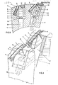
- the flaking machine comprises a body cutter head formed by a hollow steel cylinder 1, on the lateral surface of which are obtained, for example by means of milling, grooves 2 for housing blocking plugs 4 for knives 3.
- Each groove 2 has a substantially rectangular transversal section and is slanted with respect to the generatrix of the cylinder 1.
- Each of these grooves extend obliquely to form a rear portion 5, also of rectangular transversal section, in which is housed a continuous edge knive 3, a knife holder 6 provided with housing 7 for engravers 8, and a protection plate 9.
- Each plug 4 presents a passing opening 10, which extends almost the whole length of the plug itself, excluding the extremities, in correspondence of which the said plug is provided with cylindrical pins 11.
- These pins 11 may be housed in corresponding holes 12, formed on the bottom of the extreme portions of the groove 2.
- each groove 2 For the partial closure of each groove 2 an interchangeable wear element is provided 14, which is applied to the plug 4 by screws 15.
- the internal surface of said element 14 is provided with an anti-wear plate 16 while the external lateral surface is shaped in such a way so as to continue the surface of the cylinder 1.
- Each groove 2 also is connected, through a longitudinal opening 17, to the internal cavity of the cylinder 1, which at the same time is connected, through a casing 18, to an aspirator which is not shown in the drawings.
- the flaking machine operates-as follows: as soon as the body cutter head 1 comes into contact with the material 19 to be flaked, the protruding points of the engravers 8 produce engravings substantially orthogonal to the rotation axis of the element 1 and.ensure in such a way that the knives 3, although of continuous edge, cause detachment of the flakings that have substantially equal sizes from the material 19.
- Such flakings pass through the openings delimited by each knive 3 and the corresponding antiwear plate 16; they are then collected in the grooves 2 from where they are sucked by the aspirator through the longitudinal opening 17, the central hollow of the cylinder's body 1 and the casing 18.
- the flaking machine offers a number of advantages, not only with respect to traditional flaking machines with multiple rotating elements, but also to traditional centrifugal flaking machines.
- this one allows flaking of all types of wood (tree-trunks, saw-mill trimmings, chips) and can therefore be considered universal;
- the second type it presents limited wear, it does not require a previous transformation of wood into chips and, therefore, reduces the complexity of the installation, energy and work time and also allows production of evenly sized flakes.
Landscapes
- Engineering & Computer Science (AREA)
- Life Sciences & Earth Sciences (AREA)
- Manufacturing & Machinery (AREA)
- Mechanical Engineering (AREA)
- Wood Science & Technology (AREA)
- Forests & Forestry (AREA)
- Crushing And Pulverization Processes (AREA)
Applications Claiming Priority (2)
| Application Number | Priority Date | Filing Date | Title |
|---|---|---|---|
| IT84127/80A IT1141813B (it) | 1980-05-15 | 1980-05-15 | Macchina truciolatrice universale |
| IT8412780 | 1980-05-15 |
Publications (2)
| Publication Number | Publication Date |
|---|---|
| EP0040410A2 true EP0040410A2 (de) | 1981-11-25 |
| EP0040410A3 EP0040410A3 (de) | 1982-08-04 |
Family
ID=11324418
Family Applications (1)
| Application Number | Title | Priority Date | Filing Date |
|---|---|---|---|
| EP81103728A Withdrawn EP0040410A3 (de) | 1980-05-15 | 1981-05-14 | Universal-Zerspanungsmaschine |
Country Status (2)
| Country | Link |
|---|---|
| EP (1) | EP0040410A3 (de) |
| IT (1) | IT1141813B (de) |
Family Cites Families (5)
| Publication number | Priority date | Publication date | Assignee | Title |
|---|---|---|---|---|
| DE1118439B (de) * | 1957-11-04 | 1961-11-30 | Paul Kirsten Dr Ing | Werkzeugtraeger fuer Zerspanungsmaschinen zur Herstellung von Spaenen zur Spanplattenerzeugung |
| US3209801A (en) * | 1958-12-01 | 1965-10-05 | Auglo Paper Products Ltd | Wood chip producing apparatus |
| DE1143321B (de) * | 1959-09-19 | 1963-02-07 | Paul Kirsten Dr Ing | Spandickenbegrenzung an Holzzerspannungs-maschinen |
| CH419576A (de) * | 1962-09-03 | 1966-08-31 | Kirsten Paul Arthur Ing Dr | Zylindrischer Werkzeugträger für Maschinen zum Zerspanen von Holz im wesentlichen parallel zur Faser |
| DE1198530B (de) * | 1963-12-17 | 1965-08-12 | Hombak Maschinenfab Kg | Werkzeug zum Zerspanen von Holz |
-
1980
- 1980-05-15 IT IT84127/80A patent/IT1141813B/it active
-
1981
- 1981-05-14 EP EP81103728A patent/EP0040410A3/de not_active Withdrawn
Also Published As
| Publication number | Publication date |
|---|---|
| EP0040410A3 (de) | 1982-08-04 |
| IT1141813B (it) | 1986-10-08 |
| IT8084127A0 (it) | 1980-05-15 |
Similar Documents
| Publication | Publication Date | Title |
|---|---|---|
| EP0179041B1 (de) | Schneidsegment | |
| CA2034958A1 (en) | Drum-type wood chipper | |
| US4271882A (en) | Blade for a cutter for a chipper or similar wood reducing machine | |
| ES482200A1 (es) | Perfeccionamientos en maquinas trituradoras rotatorias. | |
| DE68911828D1 (de) | Vorrichtung zum Strangpressen von Lebensmitteln. | |
| ATE47806T1 (de) | Zerkleinerungsmaschine mit umlaufendem rotor. | |
| EP0040410A2 (de) | Universal-Zerspanungsmaschine | |
| ES8406549A1 (es) | Maquina cortadora de tambor,en especial para cortar remolacha de azucar en cosetas | |
| CA2196961A1 (en) | Apparatus for the resharpening of two-dimensionally acting knife sets for flaking machines, especially for wood flaking machines | |
| US5097879A (en) | Apparatus for making wood curls | |
| US3392763A (en) | Wood chipper construction | |
| US2854047A (en) | Shredder spool with bar knives | |
| FR2332108A1 (fr) | Outil a detacher des copeaux de bois | |
| US3409057A (en) | Rotary-type machine for stripping bark from round wood | |
| GB856226A (en) | Improvements in rotary cutting drums for mineral-mining machines | |
| SU1077789A1 (ru) | Узел резани стружечного станка | |
| SU1178592A1 (ru) | Рубительна машина дл измельчени древесины | |
| JPS55131369A (en) | Machine for making split "surume"(dried cuttlefish) | |
| SU982921A1 (ru) | Режущий орган рубительной машины | |
| ATE169548T1 (de) | Rotierend antreibbares schneidwerkzeug | |
| SU914276A1 (ru) | Рубильная машина 1 | |
| RU1805038C (ru) | Устройство дл резки неметаллического материала | |
| SU906405A1 (ru) | Рабочий орган фрезерной почвообрабатывающей машины | |
| SU529079A1 (ru) | Рубительна машина дл измельчени крупной щепы | |
| RU2047366C1 (ru) | Нож к измельчителю кормов |
Legal Events
| Date | Code | Title | Description |
|---|---|---|---|
| PUAI | Public reference made under article 153(3) epc to a published international application that has entered the european phase |
Free format text: ORIGINAL CODE: 0009012 |
|
| AK | Designated contracting states |
Designated state(s): AT BE CH DE FR GB |
|
| PUAL | Search report despatched |
Free format text: ORIGINAL CODE: 0009013 |
|
| AK | Designated contracting states |
Designated state(s): AT BE CH DE FR GB |
|
| STAA | Information on the status of an ep patent application or granted ep patent |
Free format text: STATUS: THE APPLICATION IS DEEMED TO BE WITHDRAWN |
|
| 18D | Application deemed to be withdrawn |
Effective date: 19830710 |
|
| RIN1 | Information on inventor provided before grant (corrected) |
Inventor name: PESSA, LUCIANO |