EP0040531B1 - Ressort à lame et lame y afférente - Google Patents
Ressort à lame et lame y afférente Download PDFInfo
- Publication number
- EP0040531B1 EP0040531B1 EP19810302181 EP81302181A EP0040531B1 EP 0040531 B1 EP0040531 B1 EP 0040531B1 EP 19810302181 EP19810302181 EP 19810302181 EP 81302181 A EP81302181 A EP 81302181A EP 0040531 B1 EP0040531 B1 EP 0040531B1
- Authority
- EP
- European Patent Office
- Prior art keywords
- leaf
- spring
- filaments
- accordance
- spring leaf
- Prior art date
- Legal status (The legal status is an assumption and is not a legal conclusion. Google has not performed a legal analysis and makes no representation as to the accuracy of the status listed.)
- Expired
Links
Images

Classifications
-
- F—MECHANICAL ENGINEERING; LIGHTING; HEATING; WEAPONS; BLASTING
- F16—ENGINEERING ELEMENTS AND UNITS; GENERAL MEASURES FOR PRODUCING AND MAINTAINING EFFECTIVE FUNCTIONING OF MACHINES OR INSTALLATIONS; THERMAL INSULATION IN GENERAL
- F16F—SPRINGS; SHOCK-ABSORBERS; MEANS FOR DAMPING VIBRATION
- F16F1/00—Springs
- F16F1/36—Springs made of rubber or other material having high internal friction, e.g. thermoplastic elastomers
- F16F1/366—Springs made of rubber or other material having high internal friction, e.g. thermoplastic elastomers made of fibre-reinforced plastics, i.e. characterised by their special construction from such materials
- F16F1/368—Leaf springs
-
- B—PERFORMING OPERATIONS; TRANSPORTING
- B29—WORKING OF PLASTICS; WORKING OF SUBSTANCES IN A PLASTIC STATE IN GENERAL
- B29C—SHAPING OR JOINING OF PLASTICS; SHAPING OF MATERIAL IN A PLASTIC STATE, NOT OTHERWISE PROVIDED FOR; AFTER-TREATMENT OF THE SHAPED PRODUCTS, e.g. REPAIRING
- B29C70/00—Shaping composites, i.e. plastics material comprising reinforcements, fillers or preformed parts, e.g. inserts
- B29C70/04—Shaping composites, i.e. plastics material comprising reinforcements, fillers or preformed parts, e.g. inserts comprising reinforcements only, e.g. self-reinforcing plastics
- B29C70/06—Fibrous reinforcements only
- B29C70/08—Fibrous reinforcements only comprising combinations of different forms of fibrous reinforcements incorporated in matrix material, forming one or more layers, and with or without non-reinforced layers
- B29C70/083—Combinations of continuous fibres or fibrous profiled structures oriented in one direction and reinforcements forming a two dimensional structure, e.g. mats
-
- B—PERFORMING OPERATIONS; TRANSPORTING
- B60—VEHICLES IN GENERAL
- B60G—VEHICLE SUSPENSION ARRANGEMENTS
- B60G11/00—Resilient suspensions characterised by arrangement, location or kind of springs
- B60G11/02—Resilient suspensions characterised by arrangement, location or kind of springs having leaf springs only
Definitions
- This invention relates to leaf springs and leaves therefor.
- Multileaf vehicular springs are disclosed in, for example, U.S. patent specifications Nos. 2052062; 3292918; and 3493222.
- springs comprising leaves which contain filamentary solids in an organic solid are disclosed in for example U.S. patents 2600843; 2829881; and 3142598.
- US-A-3900357 discloses a leaf spring composed of a plurality of overlying plies of different lengths each composed of directionally oriented filaments in a matrix of curable plastics material. The filaments are generally oriented in the longitudinal direction, but in some plies, the filaments may form cross-plies.
- US-A-3142598 discloses a spring leaf composed of filaments bound together by a solid matrix of organic plastics material and formed by a filament winding process.
- the filaments are packed substantially uniformly throughout the plastics material, extend along the length of the spring leaf, and are under slight tensile stress as a result of the winding process.
- leaf springs still tend to deteriorate relatively quickly in those parts which receive most compressive stress and also suffer from creep.
- a spring leaf comprising a longitudinally extending beam composed of from 40 to 75% by volume of filaments, the remainder comprising a continuous organic solid plastics material that binds together said filaments, at least 80% by weight of said filaments being packed substantially uniformly throughout said organic solid, extending along the beam and being under tensile stress, characterised in that some, but no more than 10% by weight, of said filaments are randomly oriented on a surface of the beam that in use is subjected to compressive loading, and in that some, but no more than 10% by weight, of said filaments are woven and lie in the body of the leaf in a place transverse to the plane in which bending of the beam will normally take place.
- the leaf comprises a beam with 50-60% by volume filamentary solids and 50-40% by volume of organic solid.
- the beam has a configuration that is substantially straight along a longitudinal axis without flexure, and a cross-section that is preferably substantially rectangular.
- This invention also includes a multileaf spring having a first leaf (normally a set of leaves comprising a first leaf) which acts independently of a second leaf under a load up to a predetermined value and a second leaf which is a spring leaf in accordance with the invention.
- the first leaf acts together with the second leaf under a load which is greater than the predetermined value.
- the first leaf preferably has ends adaptable to attach the spring to a vehicle at first and second vehicle locations.
- the second leaf preferably has a centre section bindable with a centre section of the first leaf to the vehicle at a third vehicle location. The third vehicle location is between the first and second vehicle locations.
- FIG. 1 of the drawings schematically illustrates a multileaf, multirate, composite leaf spring 150.
- the leaf spring 150 has a main leaf 156 and two secondary leaves 152 and 154.
- the composition of the main and secondary leaves 152, 154 and 156 is steel.
- the leaf spring 150 additionally incorporates a leaf 100, composed of glass fibres in a solid matrix of thermosetting organic plastics material formed into a straight flat beam.
- Configuration I of Figure 1 shows the leaf spring 150 under a new load.
- the spring 150 conforms to configuration I, when for example, a vehicle carrying it is unloaded, e.g., "curb position". It will be observed that the main and secondary leaves 156, 152 and 154 are bent, whilst the additional leaf 100 remains undeflected.
- Configuration III of Figure 1 shows the leaf spring 150 under a high load.
- the spring 150 conforms to configuration III, when, for example, a vehicle carrying has a capacity load, i.e., "normal load". In this condition all the leaves of the leaf spring 150 are bent. The rating of the spring is therefore higher in this configuration than in configuration I.
- Configuration II of Figure 1 shows the leaf spring 150 under a load intermediate between the first and second loads at which the additional leaf 100 is just about to be bent by the load.
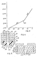
- Figure 2 approximates graphically the variation of the deflection of a leaf spring (x axis in mm.) with applied load (y axis in newtons).
- the deflection measurement corresponds to the overall height of the leaf spring.
- the measurements were made on the leaf spring 250 illustrated in Figure 3, the leaf spring being unclamped and mounted on rollers during the measurements.
- the slope of line 200 corresponds to the rating of the leaf spring when it is in configuration corresponding to that shown at I in Figure 1.
- the slope of line 202 corresponds to the rating of leaf spring 250 when it is in a configuration corresponding to that shown at III of Figure 1.
- the intersection of lines 220 and 202 represents a transition between the spring rates which occurs when the leaf spring 250 is in a configuration corresponding to that shown at in Figure 1.
- the point 201 indicates the conditions under which the main leaf of the spring 250 lies flat. This occurs at a lower load than the load at which the transition between the spring rates occurs because, unlike the leaf spring 150, the additional leaf 101 is spaced from the other leaves by a ' spacer 180.
- the leaf spring 250 has a set of steel leaves 153, 155 and 157; leaf 157 being the main leaf. These leaves give the leaf spring 250 the first spring rate.
- the additional leaf 101 comprises a beam of glass fibres in a matrix of a thermosetting plastics material. The additional leaf 101 in combination with the leaves 153, 155 and 157 produces the second spring rate.
- the main leaf 157 has mounting eyes 140 and 160 which comprise integral curvatures 162 and 142 at the ends of the main leaf 157.
- Each eye 140 and 160 contains a press fitted bush 144 and 164, within which are mounted metal sleeves 146 and 166.
- the leaf spring 250 is mounted on a vehicle through the sleeves 146 and 166(a) to the chassis or body on either side of the axle or (b) to the axle at spaced locations.
- One of the sleeves 146 and 166 is mounted to the vehicle for example by a shackle to accommodate relative movement of the ends of the leaf spring during flexing.
- a clip 170 holds the leaves 153, 155 and 157 together and towards one end of the spring 250 and prevents excessive splaying of leaves 153, 155 and 157.
- An additional clip may also be provided at the opposite end portion of the leaf spring 250 if desired. In use the clip 170, is positioned forwardly of the axle to which the spring 250 is attached, thus prevents entry of gravel or other particulate between the leaves 153, 155 and 157, particularly during acceleration of the vehicle.
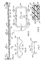
- Fastening means 190 extends through the leaves 153, 155, 157 and 101 and permits alignment of the leaf spring 250 in a spring seat 400 ( Figures 6, and 8).
- the fastening means 190 also extends through a spacer 180 (Fig. 4), and delays engagement of leaf 101 beyond "flat main leaf” condition of main leaf 157.
- the spacer 180 may be composed of aluminum or of any other such formable material.
- the fastening means 190 comprises a threaded bolt 192 having a cap 196 and a nut 194.
- the bolt 192 fits snugly in an orifice 198 through the main and secondary leaves 153, 155 and 157 and an orifice 102 through the additional leaf 101.
- the cap 196 fits into an orifice 408 in the spring seat 400.
- the spacer 180 ( Figure 4) has integral creep resistors 182 that wrap around the additional leaf 101.
- the leaf 101 has curved edges 104 that fit snugly into the intersection of the spacer portion 184 and the creep resistance portions 182 of the spacer 180.
- the creep resistance portions 182 of the spacer 180 resist movement of the leaf 101 during flexing of the spring 250.
- Figure 5 shows a cross-section through the clip 170.
- a rivet 172 fit tightly into two orifices 172 and 174 of the clip 176 and the leaf 153, respectively to maintain engagement between the clip 176 and the leaf 153.
- Figures 6, 7 and 8 show side views and a bottom view (looking up from the axle) of the spring seat 400.
- the seat 400 comprises a top, flat portion 406 upon which the leaf spring 250 rides.
- the flat portion 406 has a width equal or slightly greater than the width of leaf 101 and a length of about two times its width.
- the seat 400 has an orifice 408 into which the bolt head 196 fits.
- the spring seat 400 has a curved portion 402 which conforms to the axle housing (not shown) of the vehicle.
- the curved portion 402 is interrupted by nubs 420 which, during assembly of the spring 250 on to a vehicle, provide metal by means of which the seat 400 can be welded to the axle housing.
- the nubs 420 accordingly, disappear during the welding operation.
- the spring seat has an external curved section shown at 404 in Figures 6 and 7, which slope away from flat portion 406.
- the flat portion 406 thus forms a plateau upon which the leaf spring 250 rides, thereby providing a smooth engagement between the spring leaf 101 and the seat 400.
- Figure 8 shows sections 410 and 412 of members of U-bolt assemblies of conventional construction which wrap around the axle housing. They engage a single plate above the spring leaf 157.
- Figure 9 illustrates a cross-section through the spring leaf 101.
- the section is substantially rectangular wi.th corners having a small radius.
- Leaf 101 comprises filamentary solids in a continuous organic solid.
- Sections 500, 502 and 510 of leaf 101 show the relative positions and character of the filamentary solids in the matrix of thermosetting plastics material 504. Sections 500, 502 and 510 extend the length of leaf 101.
- the leaf 101 contains about 54% by volume of filamentary solids which comprise glass fibres; the remainder of leaf 101 is a continuous organic solid plastics material (thermoset polyester resin) that binds the filamentary solids together.
- the leaf 101 of Figure 9 has been made by a pultrusion process.
- pullers draw filaments coated with resin through a heated die.
- the resin hardens in the die. Examples of pultrusion processes appear in U.S. Patents 4,154,634; 3,853,656; 3,793,108; 3,684,622; 3,674,601; 3,530,212; and 2,741,294.
- the leaf 101 of Figure 9 has three arrangements of filaments. Greater than about 95% by weight of the filamentary solids comprise a multitude of discrete, tensilely stressed, filaments densely packed substantially uniformly throughout thermoset polyester 504. These filaments extend along leaf 101 in a plurality of planes which receive tensile or compressive stress upon flexure of multirate spring 250 sufficient to bend the spring leaf 101.
- the sections through a portion of such filaments appear as 510 in Figure 9. (The sections 510 are slightly enlarged relative to the remainder of leaf 101, and the sections of other of the filaments, substantially uniformly dispersed throughout leaf 101, have been omitted from Figure 9 for clarity.)
- the portion 502 in Figure 9 shows the position of these randomly oriented filamentary solids in the spring leaf 101.
- the randomly oriented solids form a mat (e.g. glass fibre mat) in one surface of the leaf 101.
- the mat side of leaf 101 rests on spring seat 400 in multirate spring 250 of Figure 3. (The size of the portion 502 is exaggerated for the purpose of illustration, the mat being actually only a few glass fibres thick.)
- Less than about 2% by weight of the filamentary solids in leaf 101 comprise a woven mat of filamentary solids which is held tightly within the longitudinally extending filamentary solids.
- Portions 500 of Figure 9 illustrate positions of the woven mat in leaf 101.
- the woven mat has filamentary solids positioned across one another and therefore contains fibres that are traverse to the longitudinal dimension of the spring leaf 101. These traverse fibres reduce creep of leaf 101.
- the portions 500 exaggerate for purposes of illustration the relative volume taken by the woven mats.
- Each woven mat in the leaf 101 is compressed such that it has a volume that is from 1 to 10 fibres thick in a cross-section of leaf 101.
- leaf 101 and leaves 153, 155 and 157 have equal widths.
- leaf 101 is as above described with respect to continuous and filamentary solids, but, when unloaded, is curved.
- a curved leaf may engage leaves 153, 155 and 157 before or after the main leaf has been deflected into a flat position depending, for example, on whether leaf 101 has a positive or negative curvature with respect to leaf 157.
- such a curved spring leaf may be included in the main and secondary leaves.
Landscapes
- Engineering & Computer Science (AREA)
- Mechanical Engineering (AREA)
- General Engineering & Computer Science (AREA)
- Chemical & Material Sciences (AREA)
- Composite Materials (AREA)
- Springs (AREA)
Claims (8)
Applications Claiming Priority (4)
| Application Number | Priority Date | Filing Date | Title |
|---|---|---|---|
| US15054880A | 1980-05-16 | 1980-05-16 | |
| US150548 | 1980-05-16 | ||
| US06/150,547 US4489922A (en) | 1980-05-16 | 1980-05-16 | Spring leaf comprising pultruded beam |
| US150547 | 1980-05-16 |
Publications (3)
| Publication Number | Publication Date |
|---|---|
| EP0040531A2 EP0040531A2 (fr) | 1981-11-25 |
| EP0040531A3 EP0040531A3 (en) | 1982-06-02 |
| EP0040531B1 true EP0040531B1 (fr) | 1985-02-06 |
Family
ID=26847789
Family Applications (1)
| Application Number | Title | Priority Date | Filing Date |
|---|---|---|---|
| EP19810302181 Expired EP0040531B1 (fr) | 1980-05-16 | 1981-05-18 | Ressort à lame et lame y afférente |
Country Status (3)
| Country | Link |
|---|---|
| EP (1) | EP0040531B1 (fr) |
| AU (1) | AU540761B2 (fr) |
| DE (1) | DE3168743D1 (fr) |
Families Citing this family (4)
| Publication number | Priority date | Publication date | Assignee | Title |
|---|---|---|---|---|
| US4688778A (en) * | 1982-10-01 | 1987-08-25 | Isosport Verbundbauteile Ges.M.B.H. | Plastic leaf spring |
| JPS59101359A (ja) * | 1982-12-02 | 1984-06-11 | 日本発条株式会社 | Frp板およびその製造方法 |
| DE3517807A1 (de) * | 1985-05-17 | 1986-11-20 | Böhler AG, 4000 Düsseldorf | Blattfeder |
| DE3527917A1 (de) * | 1985-08-03 | 1987-02-12 | Boehler Ag | Federblatt und verfahren zur herstellung desselben |
Family Cites Families (14)
| Publication number | Priority date | Publication date | Assignee | Title |
|---|---|---|---|---|
| US2052062A (en) * | 1935-10-28 | 1936-08-25 | Eaton Mfg Co | Spacer for leaf springs |
| US2600843A (en) * | 1952-01-24 | 1952-06-17 | Vibradamp Corp | Process for manufacturing compressible glass fiber shock absorption material and products |
| US2829881A (en) * | 1957-02-13 | 1958-04-08 | Carrier Conveyor Corp | Vibratory spring of embedded filaments |
| US3142598A (en) * | 1961-10-02 | 1964-07-28 | Pacific Plastics Company Inc | Method of making resin-impregnated glass fiber automobile leaf springs |
| DE1231967B (de) * | 1963-05-30 | 1967-01-05 | Sachsenring Automobilwerke | Glasfaser-Kunstharzfeder, insbesondere fuer Kraftfahrzeuge |
| FR1411011A (fr) * | 1963-07-24 | 1965-09-17 | Fairey Sa | Ressorts et leur procédé de fabrication |
| US3292918A (en) * | 1965-03-22 | 1966-12-20 | Charles W Hart | Variable-rate stabilizing assembly for motor vehicles |
| FR1448304A (fr) * | 1965-06-25 | 1966-08-05 | Ressorts Du Nord Sa | Ressort à lames |
| US3530212A (en) * | 1967-02-16 | 1970-09-22 | Gen Motors Corp | Method of making glass resin laminates |
| US3493222A (en) * | 1967-10-30 | 1970-02-03 | Fruehauf Corp | Spring suspension |
| US3900357A (en) * | 1970-05-04 | 1975-08-19 | Edgewater Corp | Composite material springs and manufacture |
| DE2334971C2 (de) * | 1973-07-10 | 1984-10-04 | Sigri Elektrographit Gmbh, 8901 Meitingen | Verwendung von kohlenstoffaserverstärktem Kohlenstoff als Federelement |
| GB2021731A (en) * | 1978-05-26 | 1979-12-05 | Gkn Group Services Ltd | Leaf springs of fibre-reinforced plastics |
| GB2041489A (en) * | 1978-09-29 | 1980-09-10 | Courtaulds Ltd | Composite elongate element |
-
1981
- 1981-05-15 AU AU70610/81A patent/AU540761B2/en not_active Ceased
- 1981-05-18 EP EP19810302181 patent/EP0040531B1/fr not_active Expired
- 1981-05-18 DE DE8181302181T patent/DE3168743D1/de not_active Expired
Also Published As
| Publication number | Publication date |
|---|---|
| AU540761B2 (en) | 1984-12-06 |
| EP0040531A3 (en) | 1982-06-02 |
| DE3168743D1 (en) | 1985-03-21 |
| AU7061081A (en) | 1981-11-19 |
| EP0040531A2 (fr) | 1981-11-25 |
Similar Documents
| Publication | Publication Date | Title |
|---|---|---|
| CA1220799A (fr) | Ressort non metallique a lames | |
| DE69200911T2 (de) | Elastische Abstützungsvorrichtung mit nicht-linearen elastischen Eigenschaften. | |
| US4489922A (en) | Spring leaf comprising pultruded beam | |
| US4976412A (en) | Resilient support with anisotropic stiffnesses particularly for bodywork suspensions | |
| EP3550171B1 (fr) | Dispositif de ressort à lame pour véhicule et procédé de fabrication d'un tel dispositif de ressort à lame | |
| AT516366B1 (de) | Feder für Radaufhängung und Radaufhängung | |
| US4786033A (en) | Leaf spring of composite fibre plastics material | |
| DE10221589A1 (de) | Mehrbogenverbundstoffblattfederaufbau mit variabler Federkonstante | |
| EP2472137B1 (fr) | Elément de ressort à lame et agencement de ressort à lame | |
| DE10202114A1 (de) | Verbundstoff-Bogen-Einblattfeder | |
| WO2003081076A2 (fr) | Ressort a lames hybride avec lignes de liaison renforcees | |
| EP0040531B1 (fr) | Ressort à lame et lame y afférente | |
| DE102018201435B4 (de) | Achsaufhängung | |
| DE4018459A1 (de) | Radaufhaengung | |
| DE102019212342A1 (de) | Aufhängungssystem für ein fahrzeug mit verbundfeder | |
| JPS6112467A (ja) | 回転モ−メントを伝達するための構造体およびこの構造体を巻取り成形するための芯 | |
| DE3924046C1 (fr) | ||
| DE102017215403B4 (de) | Federbaugruppe | |
| EP4217215B1 (fr) | Système de ressort à étages multiples approprié pour une utilisation dans des véhicules | |
| CA1190251A (fr) | Ressort multilame composite | |
| DE102016220376A1 (de) | Radführungseinrichtung | |
| DE102019209977A1 (de) | Achsaufhängung für ein Fahrzeug | |
| CN108506396B (zh) | 一种等截面叶片主副簧总成 | |
| DE102018206955B4 (de) | Blattfedereinheit | |
| DE69115023T2 (de) | Aufhängungssystem für ein Fahrzeug. |
Legal Events
| Date | Code | Title | Description |
|---|---|---|---|
| PUAI | Public reference made under article 153(3) epc to a published international application that has entered the european phase |
Free format text: ORIGINAL CODE: 0009012 |
|
| AK | Designated contracting states |
Designated state(s): DE FR GB IT |
|
| PUAL | Search report despatched |
Free format text: ORIGINAL CODE: 0009013 |
|
| AK | Designated contracting states |
Designated state(s): DE FR GB IT |
|
| 17P | Request for examination filed |
Effective date: 19820702 |
|
| GRAA | (expected) grant |
Free format text: ORIGINAL CODE: 0009210 |
|
| AK | Designated contracting states |
Designated state(s): DE FR GB IT |
|
| ITF | It: translation for a ep patent filed | ||
| REF | Corresponds to: |
Ref document number: 3168743 Country of ref document: DE Date of ref document: 19850321 |
|
| ET | Fr: translation filed | ||
| PLBE | No opposition filed within time limit |
Free format text: ORIGINAL CODE: 0009261 |
|
| STAA | Information on the status of an ep patent application or granted ep patent |
Free format text: STATUS: NO OPPOSITION FILED WITHIN TIME LIMIT |
|
| 26N | No opposition filed | ||
| ITTA | It: last paid annual fee | ||
| PGFP | Annual fee paid to national office [announced via postgrant information from national office to epo] |
Ref country code: GB Payment date: 19940427 Year of fee payment: 14 |
|
| PGFP | Annual fee paid to national office [announced via postgrant information from national office to epo] |
Ref country code: DE Payment date: 19940507 Year of fee payment: 14 |
|
| PGFP | Annual fee paid to national office [announced via postgrant information from national office to epo] |
Ref country code: FR Payment date: 19940819 Year of fee payment: 14 |
|
| PG25 | Lapsed in a contracting state [announced via postgrant information from national office to epo] |
Ref country code: DE Effective date: 19950401 |
|
| PG25 | Lapsed in a contracting state [announced via postgrant information from national office to epo] |
Ref country code: GB Effective date: 19950518 |
|
| GBPC | Gb: european patent ceased through non-payment of renewal fee |
Effective date: 19950518 |
|
| PG25 | Lapsed in a contracting state [announced via postgrant information from national office to epo] |
Ref country code: FR Effective date: 19960229 |
|
| REG | Reference to a national code |
Ref country code: FR Ref legal event code: ST |
|
| REG | Reference to a national code |
Ref country code: FR Ref legal event code: ST |