EP0040589A2 - Procédé et dispositif utilisant une chambre d'ionisation à transmission - Google Patents
Procédé et dispositif utilisant une chambre d'ionisation à transmission Download PDFInfo
- Publication number
- EP0040589A2 EP0040589A2 EP81850075A EP81850075A EP0040589A2 EP 0040589 A2 EP0040589 A2 EP 0040589A2 EP 81850075 A EP81850075 A EP 81850075A EP 81850075 A EP81850075 A EP 81850075A EP 0040589 A2 EP0040589 A2 EP 0040589A2
- Authority
- EP
- European Patent Office
- Prior art keywords
- electrodes
- ion chamber
- primary collimator
- centre line
- transmission
- Prior art date
- Legal status (The legal status is an assumption and is not a legal conclusion. Google has not performed a legal analysis and makes no representation as to the accuracy of the status listed.)
- Granted
Links
Images

Classifications
-
- G—PHYSICS
- G01—MEASURING; TESTING
- G01T—MEASUREMENT OF NUCLEAR OR X-RADIATION
- G01T1/00—Measuring X-radiation, gamma radiation, corpuscular radiation, or cosmic radiation
- G01T1/29—Measurement performed on radiation beams, e.g. position or section of the beam; Measurement of spatial distribution of radiation
-
- G—PHYSICS
- G21—NUCLEAR PHYSICS; NUCLEAR ENGINEERING
- G21K—HANDLING OF PARTICLES OR IONISING RADIATION NOT OTHERWISE PROVIDED FOR; IRRADIATION DEVICES; GAMMA RAY OR X-RAY MICROSCOPES
- G21K1/00—Arrangements for handling particles or ionising radiation, e.g. focusing or moderating
-
- G—PHYSICS
- G21—NUCLEAR PHYSICS; NUCLEAR ENGINEERING
- G21K—HANDLING OF PARTICLES OR IONISING RADIATION NOT OTHERWISE PROVIDED FOR; IRRADIATION DEVICES; GAMMA RAY OR X-RAY MICROSCOPES
- G21K5/00—Irradiation devices
-
- H—ELECTRICITY
- H05—ELECTRIC TECHNIQUES NOT OTHERWISE PROVIDED FOR
- H05H—PLASMA TECHNIQUE; PRODUCTION OF ACCELERATED ELECTRICALLY-CHARGED PARTICLES OR OF NEUTRONS; PRODUCTION OR ACCELERATION OF NEUTRAL MOLECULAR OR ATOMIC BEAMS
- H05H7/00—Details of devices of the types covered by groups H05H9/00, H05H11/00, H05H13/00
Definitions
- the present invention refers to a method of centering a beam of therapeutic rays by means of a transmission ion chamber and of causing the beam to be symmetric with reference to each one of a number of inner electrodes which are included in the transmission ion chamber and are located near its centre.
- the invention also refers to a transmission ion chamber for carrying out this method.
- a transmission ion chamber conventionally consists of a housing which is filled with an ionizable gas (usually air) where one or more high voltage electrodes are arranged in parallel with and spaced from one or more ion trapping electrodes.
- the transmission ion chamber is placed in a beam of ionizing radiation with its electrodes orientated generally at right angles to the central axis of the beam. If the high voltage electrodes are connected to a suitable voltage source and the ion trapping electrodes are connected to a suitable measuring system one may measure electric currents which pass from the iron trapping electrodes to earth. These currents are generally proportional to the mean value of the intensity of the beam across the iron trapping electrodes.
- the ion trapping electrodes By designing the ion trapping electrodes in a particular way and by arranging these ion trapping electrodes when designed in such particular way in special patterns it is also possible to use the ion currents of the electrodes for controlling the centering and symmetry of the beam. Examples thereof are known from the French patent specification 7302839 and from the U.S. patent specification 3 838 284.
- the said French patent specification shows a transmission ion chamber, the principal object of which is to study the homogeneity of the beam, and for this purpose two different sets of electrodes are used both of which are entirely within the beam.
- the U.S. patent specification describes a linear accelerator having a transmission ion chamber, the object of which is to measure and correct the centering and symmetry of a beam of photons.
- equalizing filter In radiotherapy with photons a so called equalizing filter is used to produce treatment fields with uniform dose distribution.
- the invention described in the U.S. patent specification utilizes properties of this equalizing filter and, therefore, can be utilized only when equalizing filters are used.
- the form and placing of the transmission ion chamber will be dependent on properties of the equalizing filter which may be specific to a particular filter.
- the equalizing filter which may be specific to a particular filter.
- the utilization of the invention described in the U.S. patent specification together with several different equalizing filters would be possible in certain cases only if the transmission ion chamber is exchanged or has its position changed and the equalizing filter is exchanged.
- the present invention aims at eliminating the limitations mentioned above and refers to a method and a device for measuring and correcting the centering and symmetry of a beam of ionizing radiation of any kind.
- the invention is not dependent on the presence of any equalizing filter.
- the characteristic features, of the invention appear from the attached claims.
- the basic idea of the invention lies in the fact that the outer electrodes are located so that these are both exposed to the beam and lie in the shadow of a primary collimator inserted in the beam.
- the primary collimator is a stationary, non-exchangeable structure element which is included in the radiotherapy device, for example a linear accelerator or microtron.
- a particle accelerator 1 emits a ray 2 of loaded particles to a ray transport system which includes four magnetic control elements 3, 4, 5 and 6. After possibly being subjected to a 90° deflection in a deflection magnet 7 the ray 2 strikes a target 8 which then emits a beam of therapeutic radiation, for example, photons, electrons, neutrons, protons or mesons.
- a primary collimator 9 confines the space angle occupied by the beam emitted by the target 8.
- the primary collimator 9 is made of a material which is substantially impervious to the beam from the target 8.
- An equalization filter 10 may be inserted under the primary collimator to change the properties of the beam, for example the dose distribution transversely across the beam.
- Such an equalization filter 10 is not required for a correct function of the transmission ion chamber according to the invention as described hereinafter.
- Such a transmission chamber 11 is placed between the primary collimator 9 and the surface 12 to be irradiated.
- the size of the surface to be irradiated is adjusted by means of a movable collimator 13.
- the transmission ion chamber 11 is used in the first place for determining the dose rate in the treatment field.
- the means used for this purpose are conventional and therefore will not be described more in detail.
- the electrodes of the transmission ion chamber 11 By arranging the electrodes of the transmission ion chamber 11 in a particular way the centering and symmetry of the beam may be sensed, and the electric signals from the electrodes may be used to correct errors possibly occurring in the centering and symmetry, respectively.
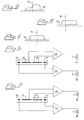
- Figure 2 shows an example of a dose distribution transversely across the field of irradiation, a so called transverse distribution, which is obtained with a beam which is centered but unsymmetric with reference to a central line 14 which is the longitudinal symmetry axis (the centre line) of the primary collimator 9 and which ideally has to pass through the effective source of radiation in the target 8.
- the central ray of the beam is marked with the dashed line 2" in Figure 1.
- Figure 3 shows an example of a transverse distribution of a symmetric but uncentered beam corresponding to Figure 2.
- the effective source of radiation is offset in relation to the longitudinal symmetry axis of the primary collimator 9.
- the central ray of the beam is marked with the dot-and-dash line 2'' in Figure 1.
- Figure 4 shows an example of a transverse distribution corresponding to Figure 2 and obtained with a correctly centered beam symmetric with the reference to the central line 14.
- the effective centre of radiation is here located on the central line 14 and the central ray of the beam coincides with the central line 14.
- Figure 5 shows an electrode arrangement in the transmission ion chamber according to the invention.
- Four flat inner electrodes 15, 16, 17, 18 are arranged in a circular area which is centered on the central line 14. This circular area has the radius R1.
- four flat outer electrodes 19, 20, 21, 22 are arranged beyond the said circular area with the radius Rl but within another circular area which has the radius R2 and which is centered on the centre line of the primary collimator.
- the primary collimator 9 collimates the beam so that its diameter in the plane of the transmission ion chamber has the radius RS.
- the radii of the electrodes 15 and 22 are chosen according to the invention so that Rl ⁇ RS ⁇ R2. Accordingly, the inner electrodes 15 to 18 will be completely exposed (i.e. will lie entirely within) the beam while the electrodes 19 to 22 are partially shaded by the primary collimator 9 which, as mentioned above, constitutes a non-exchangeable unit of the assembly.
- the electrodes 16 and 18 are connected to a differential amplifier 23 which supplies the magnetic control element 3 with a current which is proportional to the difference between the signals from the electrodes 16 and 18.
- Figure 7 shows that the electrodes 15 and 17 are connected to another differential amplifier 24 which supplies the magnetic control element 4 with a current which is proportional to the difference between the signals from the electrodes 15 and 17.
- the magnetic control elements 3 and 4 cause the beam to be symmetric with reference to the central line 14.
- a symmetrical beam is, as will be seen by comparing Figures 2, 3 and 4 with each other, a necessary but not sufficient condition that must be fulfilled if the dose distribution is to be also homogeneous or balanced across the surface 12 to be irradiated.
- a second condition which must be fulfilled is that the symmetric beam must also be centered on the central line 14.
- the outer electrodes 20 and 22 are connected to a differential amplifier 25 shown in Figure 6.
- the differential amplifier supplies the magnetic control element 5 which moves the beam 2 in a direction that tends to move the effective centre of radiation in the direction of the line V-V towards the central line 14.
- the outer electrodes are connected to a differential amplifier 26 which in turn supplies the magnetic control element 6 with a current which moves the beam 2 in a direction that tends to move the effective centre of radiation towards the central line 14 in the direction of the line VI-VI.
- the differential amplifiers 25 and 26 are designed so that they operate more slowly than the differential amplifiers 23 and 24, whereby the beam is first caused to be symmetric with reference to the central line 14 and is thereupon centered with reference to this line.
- the magnetic control elements 3 to 6 have been shown to be separate elements which are grouped two and two in the path along which the ray 2 is transported from the particle accelerator 1 to the target 8.
- one of the magnetic control elements in one or the other or in both of the groups may consist of a deflection magnet.
- the element 6 may be omitted and replaced by a deflection magnet 7 which therefore, in addition to deflecting the ray, also corrects the position thereof.
Landscapes
- Physics & Mathematics (AREA)
- Engineering & Computer Science (AREA)
- Spectroscopy & Molecular Physics (AREA)
- High Energy & Nuclear Physics (AREA)
- General Engineering & Computer Science (AREA)
- Plasma & Fusion (AREA)
- Health & Medical Sciences (AREA)
- Life Sciences & Earth Sciences (AREA)
- General Physics & Mathematics (AREA)
- Molecular Biology (AREA)
- Radiation-Therapy Devices (AREA)
Applications Claiming Priority (2)
| Application Number | Priority Date | Filing Date | Title |
|---|---|---|---|
| SE8003089 | 1980-04-23 | ||
| SE8003089A SE421257B (sv) | 1980-04-23 | 1980-04-23 | Sett att med transmissionsjonkammare centrera ett stralknippe och bringa stralknippet att bli symmetriskt med avseende pa centrumlinjen av en kollimator, samt transmissionsjonkammare for utforande av settet |
Publications (3)
| Publication Number | Publication Date |
|---|---|
| EP0040589A2 true EP0040589A2 (fr) | 1981-11-25 |
| EP0040589A3 EP0040589A3 (en) | 1981-12-02 |
| EP0040589B1 EP0040589B1 (fr) | 1985-03-13 |
Family
ID=20340816
Family Applications (1)
| Application Number | Title | Priority Date | Filing Date |
|---|---|---|---|
| EP19810850075 Expired EP0040589B1 (fr) | 1980-04-23 | 1981-04-23 | Procédé et dispositif utilisant une chambre d'ionisation à transmission |
Country Status (4)
| Country | Link |
|---|---|
| EP (1) | EP0040589B1 (fr) |
| DE (1) | DE3169228D1 (fr) |
| SE (1) | SE421257B (fr) |
| WO (1) | WO1981003084A1 (fr) |
Cited By (6)
| Publication number | Priority date | Publication date | Assignee | Title |
|---|---|---|---|---|
| EP0071826A3 (en) * | 1981-08-03 | 1983-08-03 | Siemens Aktiengesellschaft | Dose monitor chamber for electron or x-ray radiation |
| US4803368A (en) * | 1987-12-28 | 1989-02-07 | Siemens Medical Laboratories, Inc. | Assembly and method for monitoring the lateral position of a beam of ionizing radiation |
| EP0366330A1 (fr) * | 1988-10-26 | 1990-05-02 | Varian Associates, Inc. | Mesure et commande en ligne de l'énergie d'un faisceau d'électrons |
| NL2001615C2 (nl) * | 2008-05-23 | 2009-11-24 | Solimex V O F | Injectie-inrichting, voertuig, gebruik en werkwijze voor beluchting van een bodem. |
| WO2010106193A1 (fr) | 2009-03-20 | 2010-09-23 | Ion Beam Applications S.A. | Dispositif et procédé pour surveiller un faisceau d'hadrons |
| US8859980B2 (en) | 2007-03-30 | 2014-10-14 | Ion Beam Applications S.A. | Device and method for online quality assurance in hadron therapy |
Families Citing this family (1)
| Publication number | Priority date | Publication date | Assignee | Title |
|---|---|---|---|---|
| GB2571124A (en) * | 2018-02-19 | 2019-08-21 | Elekta ltd | Method and apparatus for beam energy measurement |
Family Cites Families (3)
| Publication number | Priority date | Publication date | Assignee | Title |
|---|---|---|---|---|
| FR2215701B1 (fr) * | 1973-01-26 | 1978-10-27 | Cgr Mev | |
| US3838284A (en) * | 1973-02-26 | 1974-09-24 | Varian Associates | Linear particle accelerator system having improved beam alignment and method of operation |
| US3852610A (en) * | 1973-02-26 | 1974-12-03 | Varian Associates | Transmission ion chamber |
-
1980
- 1980-04-23 SE SE8003089A patent/SE421257B/sv not_active IP Right Cessation
-
1981
- 1981-04-23 DE DE8181850075T patent/DE3169228D1/de not_active Expired
- 1981-04-23 EP EP19810850075 patent/EP0040589B1/fr not_active Expired
- 1981-04-23 WO PCT/SE1981/000123 patent/WO1981003084A1/fr not_active Ceased
Cited By (10)
| Publication number | Priority date | Publication date | Assignee | Title |
|---|---|---|---|---|
| EP0071826A3 (en) * | 1981-08-03 | 1983-08-03 | Siemens Aktiengesellschaft | Dose monitor chamber for electron or x-ray radiation |
| US4803368A (en) * | 1987-12-28 | 1989-02-07 | Siemens Medical Laboratories, Inc. | Assembly and method for monitoring the lateral position of a beam of ionizing radiation |
| EP0322656A1 (fr) * | 1987-12-28 | 1989-07-05 | Siemens Aktiengesellschaft | Dispositif et méthode de détermination de la position latérale d'un faisceau de radiation ionisante |
| EP0366330A1 (fr) * | 1988-10-26 | 1990-05-02 | Varian Associates, Inc. | Mesure et commande en ligne de l'énergie d'un faisceau d'électrons |
| AU616799B2 (en) * | 1988-10-26 | 1991-11-07 | Varian Associates, Inc. | In-line electron beam energy monitor and control |
| US8859980B2 (en) | 2007-03-30 | 2014-10-14 | Ion Beam Applications S.A. | Device and method for online quality assurance in hadron therapy |
| NL2001615C2 (nl) * | 2008-05-23 | 2009-11-24 | Solimex V O F | Injectie-inrichting, voertuig, gebruik en werkwijze voor beluchting van een bodem. |
| WO2010106193A1 (fr) | 2009-03-20 | 2010-09-23 | Ion Beam Applications S.A. | Dispositif et procédé pour surveiller un faisceau d'hadrons |
| US8779375B2 (en) | 2009-03-20 | 2014-07-15 | Ion Beam Applications S.A. | Device and method for monitoring a hadron beam |
| EP3862795A1 (fr) | 2009-03-20 | 2021-08-11 | Ion Beam Applications S.A. | Procédé de surveillance d'un faisceau d'hadrons |
Also Published As
| Publication number | Publication date |
|---|---|
| WO1981003084A1 (fr) | 1981-10-29 |
| SE421257B (sv) | 1981-12-07 |
| EP0040589A3 (en) | 1981-12-02 |
| EP0040589B1 (fr) | 1985-03-13 |
| DE3169228D1 (en) | 1985-04-18 |
| SE8003089L (sv) | 1981-10-24 |
Similar Documents
| Publication | Publication Date | Title |
|---|---|---|
| US2946892A (en) | Arrangement for controlling and correcting the location of the focal spot produced by a cathode-ray on the target of a roentgen-tube | |
| US8859980B2 (en) | Device and method for online quality assurance in hadron therapy | |
| Karzmark | Advances in linear accelerator design for radiotherapy | |
| JP6292813B2 (ja) | 放射線計測装置とそれを備えた粒子線治療装置ならびに粒子線の線量分布演算方法 | |
| Biggs et al. | Electrons as the cause of the observed dmax shift with field size in high energy photon beams | |
| CA1090484A (fr) | Dispositif pour irradier fonctionnant au moyen d'un faisceau de particules chargees | |
| JP6424198B2 (ja) | 回転可能な構台の上のエネルギー選択によるコンパクト陽子治療システム | |
| JP5791546B2 (ja) | 放射線計測装置の較正方法及び粒子線治療装置 | |
| US10471279B2 (en) | Proton dose imaging method and apparatus | |
| US8933421B2 (en) | Halo monitor in rotatable gantry for particle beam positioning | |
| US3838284A (en) | Linear particle accelerator system having improved beam alignment and method of operation | |
| US20180369612A1 (en) | Particle therapy gantry with an energy degrader and an achromatic final bending system | |
| JPH11126576A (ja) | イオン注入装置 | |
| CN107789749A (zh) | 带电粒子束偏转装置及治疗系统 | |
| EP0040589A2 (fr) | Procédé et dispositif utilisant une chambre d'ionisation à transmission | |
| US5326976A (en) | Radiation measuring device for measuring doses from a radiotherapy aparatus | |
| EP3427554B1 (fr) | Compensation de champ magnétique dans un accélérateur linéaire | |
| EP0041753B1 (fr) | Déflecteur pour faisceau de particules chargées | |
| JPH01223384A (ja) | 透過電離箱組立体、電離放射線ビームのずれ検出、補正装置とずれ検出方法、及び線形電子加速器 | |
| EP4067942A1 (fr) | Systèmes et procédés d'ionisation asymétrique bimode | |
| EP3824954A1 (fr) | Dispositif, appareil et procédé pour radiothérapie mini-faisceaux | |
| CN115569312B (zh) | 用于粒子放射治疗装置的束流控制方法及束装置 | |
| Bondarenko et al. | Heavy ion beam injection systems for fusion plasma diagnostics | |
| GB1598962A (en) | Arrangement for detecting radiation | |
| Baconnier et al. | Clic test facility the photocathode test bench |
Legal Events
| Date | Code | Title | Description |
|---|---|---|---|
| PUAI | Public reference made under article 153(3) epc to a published international application that has entered the european phase |
Free format text: ORIGINAL CODE: 0009012 |
|
| PUAL | Search report despatched |
Free format text: ORIGINAL CODE: 0009013 |
|
| AK | Designated contracting states |
Designated state(s): CH DE FR GB IT LI |
|
| AK | Designated contracting states |
Designated state(s): CH DE FR GB IT LI |
|
| 17P | Request for examination filed |
Effective date: 19820528 |
|
| ITF | It: translation for a ep patent filed | ||
| GRAA | (expected) grant |
Free format text: ORIGINAL CODE: 0009210 |
|
| AK | Designated contracting states |
Designated state(s): CH DE FR GB IT LI |
|
| REF | Corresponds to: |
Ref document number: 3169228 Country of ref document: DE Date of ref document: 19850418 |
|
| ET | Fr: translation filed | ||
| PLBI | Opposition filed |
Free format text: ORIGINAL CODE: 0009260 |
|
| 26 | Opposition filed |
Opponent name: SIEMENS AKTIENGESELLSCHAFT, BERLIN UND MUENCHEN Effective date: 19850724 |
|
| PLBN | Opposition rejected |
Free format text: ORIGINAL CODE: 0009273 |
|
| STAA | Information on the status of an ep patent application or granted ep patent |
Free format text: STATUS: OPPOSITION REJECTED |
|
| 27O | Opposition rejected |
Effective date: 19880920 |
|
| PGFP | Annual fee paid to national office [announced via postgrant information from national office to epo] |
Ref country code: GB Payment date: 19920421 Year of fee payment: 12 |
|
| PGFP | Annual fee paid to national office [announced via postgrant information from national office to epo] |
Ref country code: FR Payment date: 19920424 Year of fee payment: 12 |
|
| ITTA | It: last paid annual fee | ||
| PGFP | Annual fee paid to national office [announced via postgrant information from national office to epo] |
Ref country code: DE Payment date: 19920520 Year of fee payment: 12 |
|
| PGFP | Annual fee paid to national office [announced via postgrant information from national office to epo] |
Ref country code: CH Payment date: 19920722 Year of fee payment: 12 |
|
| PG25 | Lapsed in a contracting state [announced via postgrant information from national office to epo] |
Ref country code: GB Effective date: 19930423 |
|
| PG25 | Lapsed in a contracting state [announced via postgrant information from national office to epo] |
Ref country code: LI Effective date: 19930430 Ref country code: CH Effective date: 19930430 |
|
| GBPC | Gb: european patent ceased through non-payment of renewal fee |
Effective date: 19930423 |
|
| PG25 | Lapsed in a contracting state [announced via postgrant information from national office to epo] |
Ref country code: FR Effective date: 19931229 |
|
| REG | Reference to a national code |
Ref country code: CH Ref legal event code: PL |
|
| PG25 | Lapsed in a contracting state [announced via postgrant information from national office to epo] |
Ref country code: DE Effective date: 19940101 |
|
| REG | Reference to a national code |
Ref country code: FR Ref legal event code: ST |
|
| APAH | Appeal reference modified |
Free format text: ORIGINAL CODE: EPIDOSCREFNO |