EP0040660B1 - Dispositif d'egalisation pour lignes de transmission de données - Google Patents
Dispositif d'egalisation pour lignes de transmission de données Download PDFInfo
- Publication number
- EP0040660B1 EP0040660B1 EP80303852A EP80303852A EP0040660B1 EP 0040660 B1 EP0040660 B1 EP 0040660B1 EP 80303852 A EP80303852 A EP 80303852A EP 80303852 A EP80303852 A EP 80303852A EP 0040660 B1 EP0040660 B1 EP 0040660B1
- Authority
- EP
- European Patent Office
- Prior art keywords
- range
- transmission lines
- delay
- equalizer
- transmission line
- Prior art date
- Legal status (The legal status is an assumption and is not a legal conclusion. Google has not performed a legal analysis and makes no representation as to the accuracy of the status listed.)
- Expired
Links
- 230000005540 biological transmission Effects 0.000 title claims description 38
- 230000003111 delayed effect Effects 0.000 claims description 2
- 238000004804 winding Methods 0.000 description 3
- 238000013459 approach Methods 0.000 description 2
- 239000003990 capacitor Substances 0.000 description 2
- 238000004891 communication Methods 0.000 description 2
- 238000010586 diagram Methods 0.000 description 2
- 230000000694 effects Effects 0.000 description 1
- 230000008054 signal transmission Effects 0.000 description 1
Images
Classifications
-
- H—ELECTRICITY
- H04—ELECTRIC COMMUNICATION TECHNIQUE
- H04B—TRANSMISSION
- H04B3/00—Line transmission systems
- H04B3/02—Details
- H04B3/40—Artificial lines; Networks simulating a line of certain length
-
- H—ELECTRICITY
- H04—ELECTRIC COMMUNICATION TECHNIQUE
- H04L—TRANSMISSION OF DIGITAL INFORMATION, e.g. TELEGRAPHIC COMMUNICATION
- H04L25/00—Baseband systems
- H04L25/02—Details ; arrangements for supplying electrical power along data transmission lines
- H04L25/03—Shaping networks in transmitter or receiver, e.g. adaptive shaping networks
- H04L25/03006—Arrangements for removing intersymbol interference
- H04L25/03012—Arrangements for removing intersymbol interference operating in the time domain
- H04L25/03114—Arrangements for removing intersymbol interference operating in the time domain non-adaptive, i.e. not adjustable, manually adjustable, or adjustable only during the reception of special signals
Definitions
- the present invention relates to equalizing apparatus for data transmission lines.
- Communication and data transmission systems utilising transmission lines of various lengths have inherent problems.
- a long transmission line can cause pulse distortion and/or intersymbol interference between data bits, which will result in an erroneous signal transmission.
- Such a condition is typically corrected by the use of an equalizer to restore the signals or pulses transmitted.
- the use of such a device requires matching the frequency characteristics of the device with the frequency characteristics of a specific length of transmission line employed. If a wide range of cable lengths is involved, such as from 0 to 1823 m (5000 feet), the cable response time can vary from a subnanosecond to 1.5 microseconds and the equalizer must be adjusted to match each different length of transmission line.
- a plurality of equalizers each designed for a different range of transmission line lengths, can be provided and selectively switched into the system to accomplish this matching.
- Another approach utilised by the prior art is the use of delay lines to 'build-out' short transmission lines to a range of cable lengths for matching with an equalizer adjusted to this range of cable lengths. All of these approaches involve additional expensive components and/or are time- consuming and cumbersome to effect.
- US Patent No. 3 578 914 discloses an equalizing apparatus that can be used with a range of line lengths.
- the apparatus is complex because it monitors the received signal and adjusts automatically a variable line build-out network.
- an equalizing apparatus for a range of data bit transmission lines having a range of response times substantially between a subnanosecond and 1.5 microseconds, the apparatus comprising a delay device that is series-connected or capable of being series-connected to the data-bit transmission lines to delay a signal received therefrom and a fixed equalizer connected to the delay device to equalize the delayed signal therefrom, characterised in that the delay device is a fixed delay device providing a delay close to the high end of the range of response times of the transmission lines to convert the range to substantially between 1 and 3 microseconds.
- a preferred embodiment of the present invention described hereinbelow solves or at least alleviates the aforementioned problem associated with the prior art by introducing an additional time delay of approximately 1 microsecond into the system so that the effective response time of the transmission lines typically used, i.e., lines having lengths of from 0 to 1823 m (5000 feet), will be 1 to 3 microseconds.
- the percentage change of response time for this range of lengths is approximately 200 per cent, which is substantially less than the percentage change of response time, i.e., subnanosecond to 1.5 microseconds, prior to the introduction of this time delay. Because of this substantial reduction in the percentage change in response time, only one equalizer is necessary and it can be designed for the entire range of transmission line lengths.
- the preferred embodiment utilizes a resistance-capacitance circuit positioned between the secondary side of an input transformer and the equalizer and chosen to give the proper time delay for the range of transmission line lengths involved. Ideally, these components are chosen to give the aforementioned response time range of substantially between 1 and 3 microseconds for transmission line lengths of from 0 to 1823 m (5000 feet), respectively.
- the preferred embodiment can thus effectively equalize a wide range of transmission line lengths by means of only one equalizer which does not require adjustment thereof for each transmission line length utilised. The preferred embodiment thus does not require switching means and/or a plurality of equalizers to match the frequency characteristics of the equalizer.
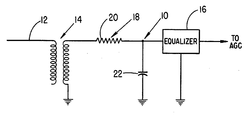
- the accompanying drawing shows a schematic diagram of a typical circuit 10 embodying the invention.
- a data bit is generated and transmitted over a transmission line 12 to a primary winding of an input transformer 14, which is optional, a secondary winding of the transformer being connected through a resistor 20, hereininafter described, to an equalizer 16.
- the output of the equalizer 16 is connected to an automatic gain control amplifier (AGC) for further processing of the signal.
- AGC automatic gain control amplifier
- a resistance-capacitance circuit 18 comprising the resistor 20 and a capacitor 22, and connected as illustrated.
- the resistance-capacitance circuit 18 introduces an additional time constant delay into the transmission circuit, as hereinafter described, so that the equalizer 16 does not require readjustment in order to accommodate different lengths of transmission line 12.
- the concept underlying the operation of the circuit 10 is the introduction of the aforementioned additional time constant delay into the transmision circuit in order to reduce the percentage change of transmission line response time for the shortest line used as compared to the longest line employed.
- transmission line lengths can vary between 0 and 1823 m (5000 feet).
- the response time for such lengths of transmission line can vary from a subnanosecond to 1.5 microseconds, and an equalizer having a frequency characteristic opposite to the characteristics of the specific transmission line length employed is generally required.
- the problem with this situation is that the range of transmission line response times (subnanosecond to 1.5 microseconds) is too wide to be handled by an equalizer without readjusting the equalizer. In essence, the percentage change of response time (subnanosecond to 1.5 microseconds) is too large to be effectively handled by a single equalizer without re-adjustment of the equalizer.
- the present circuit effectively reduces the percentage change of this response time range by adding a time constant delay of approximately 1 microsecond to the transmission system which results in short transmission lines having a response time of approximately 1 microsecond and long transmission lines having a response time of approximately 2 to 3 microseconds.
- a time constant delay of approximately 1 microsecond to the transmission system which results in short transmission lines having a response time of approximately 1 microsecond and long transmission lines having a response time of approximately 2 to 3 microseconds.
- any length of transmission line from 0 to 1823 m (5000 feet) will have a response time within a range of from 1 to 3 microseconds or 200 per cent of the shortest response time (1 microsecond), and a single equalizer can be designed to give satisfactory results for this entire range.
- the resistor 20 and the capacitor 22 can be chosen to obtain the desired response time range depending upon the lengths of transmission lines involved.
Landscapes
- Engineering & Computer Science (AREA)
- Computer Networks & Wireless Communication (AREA)
- Signal Processing (AREA)
- Power Engineering (AREA)
- Cable Transmission Systems, Equalization Of Radio And Reduction Of Echo (AREA)
- Dc Digital Transmission (AREA)
- Filters And Equalizers (AREA)
- Networks Using Active Elements (AREA)
Claims (2)
Applications Claiming Priority (2)
| Application Number | Priority Date | Filing Date | Title |
|---|---|---|---|
| US06/151,858 US4303896A (en) | 1980-05-21 | 1980-05-21 | Wide range data cable equalizer |
| US151858 | 1980-05-21 |
Publications (2)
| Publication Number | Publication Date |
|---|---|
| EP0040660A1 EP0040660A1 (fr) | 1981-12-02 |
| EP0040660B1 true EP0040660B1 (fr) | 1984-05-16 |
Family
ID=22540519
Family Applications (1)
| Application Number | Title | Priority Date | Filing Date |
|---|---|---|---|
| EP80303852A Expired EP0040660B1 (fr) | 1980-05-21 | 1980-10-29 | Dispositif d'egalisation pour lignes de transmission de données |
Country Status (10)
| Country | Link |
|---|---|
| US (1) | US4303896A (fr) |
| EP (1) | EP0040660B1 (fr) |
| JP (2) | JPS5713827A (fr) |
| AR (1) | AR231039A1 (fr) |
| AU (1) | AU523817B2 (fr) |
| BR (1) | BR8007101A (fr) |
| CA (1) | CA1143804A (fr) |
| DE (1) | DE3067883D1 (fr) |
| ES (1) | ES496491A0 (fr) |
| MX (1) | MX147979A (fr) |
Families Citing this family (12)
| Publication number | Priority date | Publication date | Assignee | Title |
|---|---|---|---|---|
| US4507793A (en) * | 1982-12-17 | 1985-03-26 | Gte Automatic Electric Incorporated | Digital signal transmission system |
| DE3514695C2 (de) * | 1985-04-24 | 1994-05-11 | Merck Patent Gmbh | Mittel und Verfahren zur Bestimmung von Calcium |
| US5268676A (en) * | 1987-09-11 | 1993-12-07 | Cybex Corporation | Computer-monitor extended range communications link |
| US4885718A (en) * | 1987-09-11 | 1989-12-05 | Cybex Corporation | Extended communications link for keyboard and display units remotely located from a computer |
| US4759035A (en) * | 1987-10-01 | 1988-07-19 | Adtran | Digitally controlled, all rate equalizer |
| EP0592747B1 (fr) * | 1992-10-15 | 1998-05-27 | International Business Machines Corporation | Dispositif et procédé pour l'égalisation adaptive dans les systèmes de transmission en anneau à jeton utilisant des câbles à paires torsadées non-blindées |
| TW304254B (fr) * | 1994-07-08 | 1997-05-01 | Hitachi Ltd | |
| US7239665B2 (en) * | 2003-11-24 | 2007-07-03 | Intel Corporation | Selection of pre-computed equalizer based on channel characteristic |
| US7656939B2 (en) * | 2004-10-25 | 2010-02-02 | Kawasaki Microelectronics America, Inc. | Adaptive equalizer with passive and active stages |
| JP2020503036A (ja) | 2016-12-27 | 2020-01-30 | ヒルズ・ペット・ニュートリシャン・インコーポレーテッド | ペットフード組成物 |
| US11616529B2 (en) * | 2021-02-12 | 2023-03-28 | Macom Technology Solutions Holdings, Inc. | Adaptive cable equalizer |
| US12021543B2 (en) | 2022-06-09 | 2024-06-25 | Macom Technology Solutions Holdings, Inc. | Baseline wander compensator and method |
Family Cites Families (6)
| Publication number | Priority date | Publication date | Assignee | Title |
|---|---|---|---|---|
| US2379744A (en) * | 1942-03-31 | 1945-07-03 | Bell Telephone Labor Inc | Electric circuit arrangement employing delay networks |
| US3135932A (en) * | 1959-08-14 | 1964-06-02 | Bell Telephone Labor Inc | Signal delay system |
| US3336539A (en) * | 1965-04-15 | 1967-08-15 | Giannini Scient Corp | Variable equalizer system having a plurality of parallel connected tuned circuits |
| US3578914A (en) * | 1969-04-09 | 1971-05-18 | Lynch Communication Systems | Equalizer with automatic line build-out |
| GB1315936A (en) * | 1969-06-23 | 1973-05-09 | Post Office | Equalizing arrangements |
| DE2613054C2 (de) * | 1976-03-26 | 1983-04-07 | Siemens AG, 1000 Berlin und 8000 München | Schaltungsanordnung zum Entzerren der Dämpfungskurve einer Nachrichtenübertragungsstrecke |
-
1980
- 1980-05-21 US US06/151,858 patent/US4303896A/en not_active Expired - Lifetime
- 1980-09-26 CA CA000361750A patent/CA1143804A/fr not_active Expired
- 1980-10-07 AU AU63009/80A patent/AU523817B2/en not_active Ceased
- 1980-10-24 MX MX184464A patent/MX147979A/es unknown
- 1980-10-29 AR AR283049A patent/AR231039A1/es active
- 1980-10-29 DE DE8080303852T patent/DE3067883D1/de not_active Expired
- 1980-10-29 EP EP80303852A patent/EP0040660B1/fr not_active Expired
- 1980-10-31 ES ES496491A patent/ES496491A0/es active Granted
- 1980-12-15 JP JP17597880A patent/JPS5713827A/ja active Pending
-
1981
- 1981-10-30 BR BR8007101A patent/BR8007101A/pt unknown
-
1984
- 1984-07-27 JP JP1984113614U patent/JPS6047353U/ja active Pending
Also Published As
| Publication number | Publication date |
|---|---|
| ES8202664A1 (es) | 1981-12-01 |
| AU523817B2 (en) | 1982-08-19 |
| DE3067883D1 (en) | 1984-06-20 |
| AU6300980A (en) | 1981-11-26 |
| MX147979A (es) | 1983-02-21 |
| ES496491A0 (es) | 1981-12-01 |
| JPS6047353U (ja) | 1985-04-03 |
| EP0040660A1 (fr) | 1981-12-02 |
| CA1143804A (fr) | 1983-03-29 |
| BR8007101A (pt) | 1982-06-22 |
| JPS5713827A (en) | 1982-01-23 |
| AR231039A1 (es) | 1984-08-31 |
| US4303896A (en) | 1981-12-01 |
Similar Documents
| Publication | Publication Date | Title |
|---|---|---|
| EP0040660B1 (fr) | Dispositif d'egalisation pour lignes de transmission de données | |
| GB1380651A (en) | Transversal equalizers | |
| CA1226346A (fr) | Methode et circuit de compensation de la diaphonie et/ou des signaux d'echo | |
| US4450555A (en) | Device for minimizing far-end crosstalk between half-duplex digital transmission lines | |
| US5699022A (en) | Adaptive cable equalizer | |
| CA2071551A1 (fr) | Dispositif et methode de correction des effets dus a la tension de decalage continue dans un recepteur | |
| EP2658197B1 (fr) | Circuit et procédés d'égalisation de récepteur programmable | |
| JPH0767104B2 (ja) | 2線回線による完全双信デ−タ伝送装置 | |
| JPS594336A (ja) | 複合伝送システムに於けるタ−ミナル装置 | |
| EP0459687A2 (fr) | Correcteur transversal à ondes progressives | |
| JPS6349928B2 (fr) | ||
| EP0592747B1 (fr) | Dispositif et procédé pour l'égalisation adaptive dans les systèmes de transmission en anneau à jeton utilisant des câbles à paires torsadées non-blindées | |
| US4887278A (en) | Equalizer for digital transmission systems | |
| US3812436A (en) | Waveform equalizer system | |
| US4491808A (en) | Equalizer circuit for use in communication unit | |
| US5517523A (en) | Bridge-tap equalizer method and apparatus | |
| US3609597A (en) | Self-adaptive equalizer for time-varying channels | |
| US5245556A (en) | Adaptive equalizer method and apparatus | |
| US4785265A (en) | Enhanced automatic line build out | |
| US5506549A (en) | Cable equalizer | |
| EP0123315B1 (fr) | Procédé d'égalisation de type transversal | |
| US7440525B2 (en) | Dynamic range signal to noise optimization system and method for receiver | |
| US4899365A (en) | Apparatus and method for adaptive amplitude equalization | |
| US4606043A (en) | Programmable automatic cable equalizer | |
| US4912725A (en) | Adaptive equalizer included in the receiver for a data transmission system |
Legal Events
| Date | Code | Title | Description |
|---|---|---|---|
| PUAI | Public reference made under article 153(3) epc to a published international application that has entered the european phase |
Free format text: ORIGINAL CODE: 0009012 |
|
| AK | Designated contracting states |
Designated state(s): DE FR GB IT |
|
| 17P | Request for examination filed |
Effective date: 19811012 |
|
| ITF | It: translation for a ep patent filed | ||
| GRAA | (expected) grant |
Free format text: ORIGINAL CODE: 0009210 |
|
| AK | Designated contracting states |
Designated state(s): DE FR GB IT |
|
| REF | Corresponds to: |
Ref document number: 3067883 Country of ref document: DE Date of ref document: 19840620 |
|
| ET | Fr: translation filed | ||
| PLBE | No opposition filed within time limit |
Free format text: ORIGINAL CODE: 0009261 |
|
| STAA | Information on the status of an ep patent application or granted ep patent |
Free format text: STATUS: NO OPPOSITION FILED WITHIN TIME LIMIT |
|
| 26N | No opposition filed | ||
| PGFP | Annual fee paid to national office [announced via postgrant information from national office to epo] |
Ref country code: GB Payment date: 19901001 Year of fee payment: 11 |
|
| PGFP | Annual fee paid to national office [announced via postgrant information from national office to epo] |
Ref country code: FR Payment date: 19901022 Year of fee payment: 11 |
|
| PGFP | Annual fee paid to national office [announced via postgrant information from national office to epo] |
Ref country code: DE Payment date: 19901026 Year of fee payment: 11 |
|
| ITTA | It: last paid annual fee | ||
| PG25 | Lapsed in a contracting state [announced via postgrant information from national office to epo] |
Ref country code: GB Effective date: 19911029 |
|
| GBPC | Gb: european patent ceased through non-payment of renewal fee | ||
| PG25 | Lapsed in a contracting state [announced via postgrant information from national office to epo] |
Ref country code: FR Effective date: 19920630 |
|
| PG25 | Lapsed in a contracting state [announced via postgrant information from national office to epo] |
Ref country code: DE Effective date: 19920701 |
|
| REG | Reference to a national code |
Ref country code: FR Ref legal event code: ST |