EP0040683A2 - Agrafeuse chirurgicale - Google Patents
Agrafeuse chirurgicale Download PDFInfo
- Publication number
- EP0040683A2 EP0040683A2 EP81102258A EP81102258A EP0040683A2 EP 0040683 A2 EP0040683 A2 EP 0040683A2 EP 81102258 A EP81102258 A EP 81102258A EP 81102258 A EP81102258 A EP 81102258A EP 0040683 A2 EP0040683 A2 EP 0040683A2
- Authority
- EP
- European Patent Office
- Prior art keywords
- staple
- trigger
- handle
- track
- anvil surface
- Prior art date
- Legal status (The legal status is an assumption and is not a legal conclusion. Google has not performed a legal analysis and makes no representation as to the accuracy of the status listed.)
- Granted
Links
Images




Classifications
-
- A—HUMAN NECESSITIES
- A61—MEDICAL OR VETERINARY SCIENCE; HYGIENE
- A61B—DIAGNOSIS; SURGERY; IDENTIFICATION
- A61B17/00—Surgical instruments, devices or methods
- A61B17/04—Surgical instruments, devices or methods for suturing wounds; Holders or packages for needles or suture materials
-
- A—HUMAN NECESSITIES
- A61—MEDICAL OR VETERINARY SCIENCE; HYGIENE
- A61B—DIAGNOSIS; SURGERY; IDENTIFICATION
- A61B17/00—Surgical instruments, devices or methods
- A61B17/068—Surgical staplers, e.g. containing multiple staples or clamps
- A61B17/0682—Surgical staplers, e.g. containing multiple staples or clamps for applying U-shaped staples or clamps, e.g. without a forming anvil
- A61B17/0684—Surgical staplers, e.g. containing multiple staples or clamps for applying U-shaped staples or clamps, e.g. without a forming anvil having a forming anvil staying above the tissue during stapling
-
- A—HUMAN NECESSITIES
- A61—MEDICAL OR VETERINARY SCIENCE; HYGIENE
- A61B—DIAGNOSIS; SURGERY; IDENTIFICATION
- A61B17/00—Surgical instruments, devices or methods
- A61B17/10—Surgical instruments, devices or methods for applying or removing wound clamps, e.g. containing only one clamp or staple; Wound clamp magazines
Definitions
- This invention relates to a surgical skin/fascia stapling instrument which contains a plurality of staples and which allows a single staple to be formed and removed from the instrument.
- This invention also relates to a surgical stapling instrument from partially forming a staple and then returning and picking up the next staple.
- the stapling instrument of this invention has advantages over the prior art.
- One advantage is the relative size of the instrument which is maintained while the number of mechanical parts is decreased. Therefore, as a general statement, the ease of operation and the reliability of the instrument is improved.
- the operation and reliability of an instrument can be critical in the surgical operating area where even seconds may determine if a surgical operation or procedure is a success.
- Another advantage is the orientation of the flange on the anvil surface.
- the flange orientation is opposite to the direction of stapling. For most surgeons, the natural direction of stapling is always away from their body.
- the orientation of the flange allows the surgeon to advance the instrument and remove the formed staple in a direction away from the body. This has still another advantage in that while stapling the surgeon cannot accidentally brush against the open wound site.
- Still another advantage of this instrument is the stapling indicator which is on top of the handle. The instrument thus does not have to be turned over to determine the number of staples remaining in the instrument. Still further, another advantage is the location of the. trigger means which are internal to the handle. This seems to provide a more sterile environment and to prevent or decrease the liklihood of pinching a finger or fingers during use. Yet another advantage is the configuration of the instrument. In many surgical procedures, the instrument configuration may give a better field of vision of the wound site to the surgeon.
- the surgical stapling control means also has advantages over the prior art.
- the control means prevents the trigger from returning to its initial pos- iton if the compression is interrupted. This, has the advantage of preventing a second staple from being formed on the anvil flange before a first staple is separated from the instrument.
- Another advantage of the control means is interrupted stapling. The surgeon can now stop the compression of the trigger into the handle to realign the instrument over the wound site. Thus, the possibility of a perfect stapling procedure is greatly enhanced.
- the control means are automatically disengaged on completely compressing the trigger. Thus, the control means do not have to be manually reset after a single staple is formed and separated from the instrument.
- a surgical stapling instrument comprising a handle and a trigger pivotally attached and on compression internal to the handle has now been invented.
- the forward portion of the handle contains a track; a plurality of staples loaded and staple advancing means carried on the track; a track cover mounted on the track; an anvil surface mounted and a first bias means movably mounted on the cover, the said anvil surface terminating in a perpendicular flange; a staple adjacent the anvil surface; and a retainer spring mounted on the anvil surface and. separating the staple from the flange.
- An alternative surgical stapling instrument comprising a handle and a trigger pivotally attached and on compression internal to said handle has also been invented,
- the forward portion of the handle contains: a track; a leaf spring on the terminal end of said track; a plurality of staples loaded and staple advancing means carried on said track; a track cover mounted on said track; an anvil surface mounted and a first bias means movably mounted on the cover, the said anvil surface terminating in a perpendicular flange; and a staple adjacent said anvil surface separated from said flange by said leaf spring.
- the forward portion of the handle also contains a guide block which is mounted on the track cover adjacent the anvil surface.
- a forming blade and a second bias means are movably mounted on the guide block, the forming blade and the trigger having coordinating surfaces.
- the forming blade pushes the staple downward, the staple displaces the leaf spring, the leaf spring moves back to its initial position and the staple forms on the flange.
- the formed staple is separated from the flange, the second bias means returns the trigger and the forming blade to their initial positions, and the first bias means activates the staple advancing means to place the forwardmost staple adjacent the anvil surface.
- the track cover can be adjacent the forward portion of the trigger and/or the forming blade can be located between the forward portion of the track cover and the anvil surface.
- One embodiment of the stapling instrument or of the alternative stapling instrument described above comprises an indicator to indicate the number of staples remaining in the instrument.
- the indicator has an initial end visible in the handle.
- a terminal end is movably mounted on the staple advancing means such that on releasing the trigger, the first bias means pulls the terminal end and thus moves the initial end of the indicator.
- a surgical stapling control means has now been invented.
- the control means are contained in a surgical instrument comprising a handle; a trigger pivotally attached and on compression internal to said handle; and staple forming means contained in the forward portion of the handle.
- the control means comprise a multi-toothed ratchet on the rearward position of the trigger; at least one guide pin attached to the initial end of the ratchet; a nonpivoting pawl attached to the rearward portion of the handle to coordinate with the ratchet; and guide means adjacent the rearward portion of the handle to coordinate with and provide tension to the guide pin.
- control means are contained in a surgical instrument comprising a handle; a trigger pivotally attached and on compression internal to said handle; and staple forming means contained in the forward portion of said handle.
- the alternative control means comprise a multi--toothed ratchet on the rearward portion of the handle; a pawl attached to the rearward portion of the trigger to coordinate with the ratchet; at least one guide pin attached to the initial end of the pawl; and guide means adjacent the rearward portion of said handle to coordinate with and provide tension to the guide pin.
- the guide means On partially compressing the trigger the guide means provide tension on the guide pin and the ratchet engages the pawl. On completely compressing the trigger, the guide pin crosses over the top of the guide means causing the ratchet to be disengaged from the pawl.
- the guide means described above are two cams attached to each side of the handles.
- the stapling control means comprises two guide pins to coordinate with the two cams.
- the staple forming means described above is a track; a plurality of staples loaded and staple advancing means carried on the track; a track cover mounted on the track; an anvil surface mounted and a first bias means movably mounted on the cover, the said anvil surface terminating in a perpendicular flange; a staple adjacent the anvil surface; a retainer spring mounted on the anvil surface or a leaf spring on the terminal end of the track, and separating the staple from the flange; a guide block mounted on the cover adjacent the anvil surface; and a forming blade and a second bias means movably mounted on the guide means, the forming blade and the trigger having coordinating surfaces.
- the trigger has "overtravel". That is on compressing the trigger into the handle the staple forms on the flange before the guide pins cross over the top of the guide means causing the ratchet to be disengaged from the pawl.
- the track cover can be adjacent the forward portion of the trigger, and/or the forming blade can be between the forward portion of the cover and the anvil surface.
- the stapling instrument described above comprises an indicator to indicate the number of staples remaining in the instrument.
- the indicator has an initial end visible in the handle.
- a terminal end is movably mounted on the staple advancing means such that on releasing the trigger, the first bias means pulls the terminal end and thus moves the initial end of the indicator
- a method of using the stapling instruments or of using the stapling instruments with the control means is within the scope of this invention.
- a method of closing a wound or of connecting skin or fascia comprises: joining the adjacent edges of the wound or skin or fascia; placing the stapling instrument or the alternative stapling instrument with or without the control means or the alternative control means described above adjacent to the wound or to the skin or fascia; compressing the trigger into the handle; and releasing the trigger and advancing the instrument, whereby a formed staple is placed between the edges.
- the instrument comprises a handle 1 and a trigger 2.
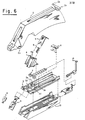
- a staple track 10 (more fully described in Figures 6 and 9 to 10) is inserted and attached to the forward portion of the handle 1, for example by cementing or sonic welding.
- the initial end of an indicator 13 is visible through an opening in the forward top portion of the handle 1.
- a combined ratchet stop and cover 14 (more fully described in Figures 4 and 5) is attached to the rear portion of handle 1.
- the track cover 3 is assembled as follows.
- the first bias means 7, which preferably is a negator spring, is mounted into the openings 3a in track cover 3.
- Retainer spring 15 is inserted onto bending anvil retainer tabs 9a.
- the bending anvil 9 and the retainer spring 15 are then placed through the opening 3b.
- the terminal end 13a of indicator 13 is mounted onto the track cover 3 in front of the spring 7 and protrudes through the bottom 3c of the track cover 3.
- the guide block 4 is mounted under tabs 3d.
- a locking wedge 8 is then pushed into slots 3e to hold the guide block 4 on the track cover 3.
- Other means for holding the guide block on the track cover can be used, for example bonding, riveting, peening, tacking or welding.
- the second bias means 6, preferably a spring, is inserted into the guide block opening 4a.
- the forming blade 5 is mounted through the guides 4b in the guide block.
- the vertical surface of the forming blade 5 is between the forward portion of the track cover 3 and the anvil surface 9.
- staples 12 are loaded onto the track 10.
- the staple advancing means preferably a staple pusher 11 is carried on the track 10 behind the staples 12 by the first bias means 7 (shown e.g., in Figure 8).
- the indicator 13 is carried with the staple pusher 11 by the first bias means 7.
- the staples 12 in Figures 9 and 10 are shown in their orientation when the instrument is in the position shown in Figure 1.
- the track cover 3 is then mounted onto the track 10 for example by sonic welding.
- the spring 7 is then attached to the advancing means tab lla by pulling back on the indicator 13 and engaging the center of the extended spring 7 with the advancing means tab lla.
- the trigger pivots 2aa are placed against stops in the forward portion of the handle 1.
- the track cover 3 and track 10 are then inserted and attached to the forward portion of the handle 1, for example by cementing or sonic welding.
- the trigger pivots 2aaare thus captured.
- the stapling instrument is used by placing the anvil surface 9 adjacent a wound opening or between skin or fascia.
- the trigger 2 is then compressed into the handle 1 (shown in Figure 1).
- the front end of trigger 2 engages the top flange of forming blade 5, forcing it down thru the guides 4b on guide block 4.
- the lower edges of the forming blade have a recessed area to engage staple 12.
- the staple is pushed downward and forced to bend at right angles on either side of the lower flange of anvil 9.
- the staple 12 In the initial or rest position, the staple 12 is adjacent the vertical surface of the anvil 9, as shown in Figure 12.
- the forming blade 5 lowers and pushes the staple downward and onto the anvil flange.
- the forming of the staple around the anvil lower flange is well known in the prior art.
- a multi-toothed ratchet 2a is built into the rear of the trigger 2 and cam guides lb into handle 1.
- the ratchet 2a engages stop 14a and prevents the trigger from returning to its relaxed position.
- the trigger must be compressed past the last ratchet tooth 2a and must be completely closed so that the guide pins 2b (more fully shown in Figure 6) move up and cross over-the cam guides lb.
- the guide pins are spring loaded. Thus when the trigger is completely compressed, the guide pins cross over the top of the cam guides lb. On releasing the trigger from a final compression, the ratchet is thus prevented from locking on the stop 14a.
- a multi-toothed ratchet 16a is built into the cover 16.
- a stop 2c is built into the trigger 2.
- Cam guides lb are built into handle 1. When the trigger 2 is compressed, the ratchet 16a engages stop 2c and prevents the trigger from returning to its relaxed position. The trigger must be compressed past the last ratchet tooth 16a and must be completely closed so that the guide pins 2b (more fully shown in Figure 6)move up and cross over the cam guides lb.
- the guide pins 2b are spring loaded. Thus when the trigger is completely compressed, the guide pins cross over the top of the cam guides lb. On releasing the trigger from a final compression, the ratchet is thus prevented from locking on the stop 2c.
- the track cover 3 is assembled as follows.
- the forward portion of the track cover is identical to that shown in Figures 6 to 8.
- the bias means 7 (not shown) and the bending anvil 9 are mounted identically to the description in Figures 6 to 8 and 17.
- the front tabs 10a on the track 10 pass through the slots 9a and then fold onto the bending anvil 9. As shown more fully in Figure 24, the front tabs 10a and the slots 9a are sufficiently wide to allow the forming blade 5 to move.
- the terminal end 13a of indicator 13 (not shown) is mounted identically to the description in Figures 6 to 10.
- the guide block 4 is mounted under tabs 3d as shown in Figures 6 to 8 and 17.
- Blocks 3f are adjacent slots 3h on the track cover 3.
- Blocks 3f diagonally support the guide block 4 on the track cover 3.
- Forward vertical tabs 10b on the track 10 pass through the forward openings 3a in the track cover 3 and then fold onto the portion of the guide block 4 in slots 3h to hold the guide block on the track cover.
- Rear vertical tabs 10b pass through the rear openings 3g and then fold onto the track cover 3.
- the second bias means 6 and the forming blade 5 are mounted indentically to the description in Figures 6 & 17.
- Figures 22 and 23 show an alternative embodiment of the track 10.
- the track 10 contains a leaf spring 10c on the terminal end of the track.
- the leaf spring separates the staple adjacent to the anvil surface from the anvil flange,
- the staples 12, staple advancing means 11, and indicator 13 are carried on the track 10 and are indentical to the description in Figures 9 and 10.
- the stapling instrument with the alternative embodiments is used by placing the anvil surface 9 adjacent a wound opening or between skin or fascia.
- the trigger 2 (shown in Figure 1) is then compressed into the handle 1.
- the front end of trigger 2 engages the top flange of forming blade 5, forcing it down thru the guides 4b (shown in Figure 17) on guide block 4.
- the lower edges of the forming blade have a recessed area to engage staple 12.
- the staple is pushed downward and displaces the leaf spring 10c.
- the leaf spring 10c then moves back to its initial position to hold the next staple at the terminal end of track 10 and adjacent the anvil surface.
- the forming blade 5 continues to engage staple 12 which is then forced to bend at right angles on either side of the lower flange of anvil 9.
- the staple 12 In the initial or rest position, the staple 12 is adjacent the vertical surface of the anvil 9, as shown in Figure 25.
- the forming blade 5 lowers and pushes the staple downward and onto the anvil flange.
- the staple 12 is separated from the anvil flange.
Landscapes
- Health & Medical Sciences (AREA)
- Life Sciences & Earth Sciences (AREA)
- Surgery (AREA)
- Molecular Biology (AREA)
- General Health & Medical Sciences (AREA)
- Biomedical Technology (AREA)
- Heart & Thoracic Surgery (AREA)
- Medical Informatics (AREA)
- Nuclear Medicine, Radiotherapy & Molecular Imaging (AREA)
- Animal Behavior & Ethology (AREA)
- Engineering & Computer Science (AREA)
- Public Health (AREA)
- Veterinary Medicine (AREA)
- Surgical Instruments (AREA)
- Portable Nailing Machines And Staplers (AREA)
- Pharmaceuticals Containing Other Organic And Inorganic Compounds (AREA)
- Acyclic And Carbocyclic Compounds In Medicinal Compositions (AREA)
Applications Claiming Priority (4)
| Application Number | Priority Date | Filing Date | Title |
|---|---|---|---|
| US15322980A | 1980-05-27 | 1980-05-27 | |
| US15322880A | 1980-05-27 | 1980-05-27 | |
| US153229 | 1980-05-27 | ||
| US153228 | 1980-05-27 |
Publications (3)
| Publication Number | Publication Date |
|---|---|
| EP0040683A2 true EP0040683A2 (fr) | 1981-12-02 |
| EP0040683A3 EP0040683A3 (en) | 1982-02-10 |
| EP0040683B1 EP0040683B1 (fr) | 1986-02-19 |
Family
ID=26850318
Family Applications (1)
| Application Number | Title | Priority Date | Filing Date |
|---|---|---|---|
| EP81102258A Expired EP0040683B1 (fr) | 1980-05-27 | 1981-03-25 | Agrafeuse chirurgicale |
Country Status (12)
| Country | Link |
|---|---|
| EP (1) | EP0040683B1 (fr) |
| KR (1) | KR840000759B1 (fr) |
| AR (1) | AR226718A1 (fr) |
| AU (1) | AU551749B2 (fr) |
| BR (1) | BR8101783A (fr) |
| CA (1) | CA1174932A (fr) |
| DE (1) | DE3173792D1 (fr) |
| DK (1) | DK161938C (fr) |
| ES (1) | ES500704A0 (fr) |
| FI (1) | FI73590C (fr) |
| MX (1) | MX150766A (fr) |
| NO (1) | NO156513C (fr) |
Cited By (10)
| Publication number | Priority date | Publication date | Assignee | Title |
|---|---|---|---|---|
| EP0076744A1 (fr) * | 1981-10-02 | 1983-04-13 | United States Surgical Corporation | Appareil d'agrafage chirurgical avec un poussoir d'agrafe courbé |
| FR2524295A1 (fr) * | 1982-04-05 | 1983-10-07 | Senco Products | Instrument d'agrafage chirurgical et cartouche d'agrafes pour celui-ci |
| EP0069557A3 (en) * | 1981-07-08 | 1984-01-18 | Howmedica Inc. | Surgical stapler |
| WO1984001706A1 (fr) * | 1982-11-04 | 1984-05-10 | Minnesota Mining & Mfg | Agrafeuse a enclume escamotable |
| EP0094752A3 (en) * | 1982-05-04 | 1984-10-24 | Joseph Walter Blake Iii | Surgical stapler |
| EP0167217A1 (fr) * | 1984-05-10 | 1986-01-08 | Ethicon, Inc. | Instrument d'agrafage chirurgical |
| EP0203375A3 (fr) * | 1985-04-26 | 1988-07-13 | Edward Weck Inc. | Dispositif pour stocker et appliquer des agrafes chirurgicales |
| DE3934698A1 (de) * | 1989-10-18 | 1991-04-25 | Beiersdorf Ag | Chirurgisches geraet zum setzen von wundklammern |
| EP0436166A1 (fr) * | 1989-12-21 | 1991-07-10 | Edward Weck Incorporated | Instrument d'agrafage chirurgical |
| EP0442482A3 (en) * | 1990-02-13 | 1991-11-06 | Ethicon Inc. | Rotating head skin stapler |
Families Citing this family (1)
| Publication number | Priority date | Publication date | Assignee | Title |
|---|---|---|---|---|
| WO1985005025A1 (fr) * | 1984-05-07 | 1985-11-21 | Puchy David P W | Agrafeuse chirurgicale a degre variable de fermeture des agrafes |
Family Cites Families (9)
| Publication number | Priority date | Publication date | Assignee | Title |
|---|---|---|---|---|
| US1452373A (en) * | 1921-10-15 | 1923-04-17 | Gomez Joaquin Sanchez | Surgical ligature and means for applying the same |
| US2275548A (en) * | 1940-08-16 | 1942-03-10 | Acme Staple Company | Stapling machine |
| DE819088C (de) * | 1950-01-24 | 1951-10-29 | Karl Kammer | Heftgeraet |
| US2660725A (en) * | 1953-01-21 | 1953-12-01 | Frank R Curtiss | Stapling device |
| GB939929A (en) * | 1959-10-30 | 1963-10-16 | Vasilii Fedotovich Goodov | Instrument for stitching blood vessels, intestines, bronchi and other soft tissues |
| US3510043A (en) * | 1967-05-22 | 1970-05-05 | Larson Co Charles O | Stapling machine |
| US3873016A (en) * | 1973-11-30 | 1975-03-25 | Meyer Fishbein | Pliers type surgical stapler for joining disunited skin or fascia |
| US4043504A (en) * | 1976-03-09 | 1977-08-23 | Senco Products, Inc. | Staple cartridge and feed means for use with a surgical stapling instrument |
| US4179057A (en) * | 1978-11-17 | 1979-12-18 | Senco Products, Inc. | Disposable surgical stapling instrument |
-
1981
- 1981-03-23 KR KR8100946A patent/KR840000759B1/ko not_active Expired
- 1981-03-25 AU AU68728/81A patent/AU551749B2/en not_active Ceased
- 1981-03-25 BR BR8101783A patent/BR8101783A/pt not_active IP Right Cessation
- 1981-03-25 CA CA000373775A patent/CA1174932A/fr not_active Expired
- 1981-03-25 NO NO811012A patent/NO156513C/no unknown
- 1981-03-25 EP EP81102258A patent/EP0040683B1/fr not_active Expired
- 1981-03-25 DK DK135181A patent/DK161938C/da not_active IP Right Cessation
- 1981-03-25 FI FI810916A patent/FI73590C/fi not_active IP Right Cessation
- 1981-03-25 AR AR284734A patent/AR226718A1/es active
- 1981-03-25 DE DE8181102258T patent/DE3173792D1/de not_active Expired
- 1981-03-25 ES ES500704A patent/ES500704A0/es active Granted
- 1981-05-26 MX MX187471A patent/MX150766A/es unknown
Cited By (15)
| Publication number | Priority date | Publication date | Assignee | Title |
|---|---|---|---|---|
| EP0069557A3 (en) * | 1981-07-08 | 1984-01-18 | Howmedica Inc. | Surgical stapler |
| EP0076744A1 (fr) * | 1981-10-02 | 1983-04-13 | United States Surgical Corporation | Appareil d'agrafage chirurgical avec un poussoir d'agrafe courbé |
| FR2524295A1 (fr) * | 1982-04-05 | 1983-10-07 | Senco Products | Instrument d'agrafage chirurgical et cartouche d'agrafes pour celui-ci |
| GB2117693A (en) * | 1982-04-05 | 1983-10-19 | Senco Products | Surgical stapling instrument and cartridge therefor |
| EP0094752A3 (en) * | 1982-05-04 | 1984-10-24 | Joseph Walter Blake Iii | Surgical stapler |
| US4527725A (en) * | 1982-11-04 | 1985-07-09 | Minnesota Mining And Manufacturing Company | Stapler with retractable anvil |
| WO1984001706A1 (fr) * | 1982-11-04 | 1984-05-10 | Minnesota Mining & Mfg | Agrafeuse a enclume escamotable |
| EP0167217A1 (fr) * | 1984-05-10 | 1986-01-08 | Ethicon, Inc. | Instrument d'agrafage chirurgical |
| US4796793A (en) * | 1984-05-10 | 1989-01-10 | Ethicon, Inc. | Surgical stapler and methods |
| EP0203375A3 (fr) * | 1985-04-26 | 1988-07-13 | Edward Weck Inc. | Dispositif pour stocker et appliquer des agrafes chirurgicales |
| AU598732B2 (en) * | 1985-04-26 | 1990-07-05 | Edward Weck & Company, Inc. | Method and apparatus for storing, dispensing and applying surgical staples |
| DE3934698A1 (de) * | 1989-10-18 | 1991-04-25 | Beiersdorf Ag | Chirurgisches geraet zum setzen von wundklammern |
| EP0436166A1 (fr) * | 1989-12-21 | 1991-07-10 | Edward Weck Incorporated | Instrument d'agrafage chirurgical |
| EP0442482A3 (en) * | 1990-02-13 | 1991-11-06 | Ethicon Inc. | Rotating head skin stapler |
| GR910100071A (en) * | 1990-02-13 | 1992-06-30 | Ethicon Inc | Rotating head skin stapler |
Also Published As
| Publication number | Publication date |
|---|---|
| FI73590C (fi) | 1987-11-09 |
| FI73590B (fi) | 1987-07-31 |
| NO811012L (no) | 1981-11-30 |
| EP0040683A3 (en) | 1982-02-10 |
| KR830004834A (ko) | 1983-07-20 |
| AR226718A1 (es) | 1982-08-13 |
| DE3173792D1 (en) | 1986-03-27 |
| FI810916L (fi) | 1981-11-28 |
| KR840000759B1 (en) | 1984-06-08 |
| NO156513B (no) | 1987-06-29 |
| AU551749B2 (en) | 1986-05-08 |
| BR8101783A (pt) | 1981-09-29 |
| DK161938C (da) | 1992-02-10 |
| NO156513C (no) | 1987-10-07 |
| DK135181A (da) | 1981-11-28 |
| AU6872881A (en) | 1981-12-03 |
| ES8203217A1 (es) | 1982-04-01 |
| DK161938B (da) | 1991-09-02 |
| EP0040683B1 (fr) | 1986-02-19 |
| MX150766A (es) | 1984-07-12 |
| CA1174932A (fr) | 1984-09-25 |
| ES500704A0 (es) | 1982-04-01 |
Similar Documents
| Publication | Publication Date | Title |
|---|---|---|
| US4591086A (en) | Surgical stapling instrument | |
| US4406392A (en) | Surgical stapling instrument | |
| US4391402A (en) | Surgical stapling control means | |
| US4316468A (en) | Surgical stapler | |
| US4452357A (en) | Surgical stapler | |
| EP0000756B1 (fr) | Agrafeuse chirurgicale | |
| US5049152A (en) | Hemostatic clip applicator | |
| US5456400A (en) | Apparatus and clip for fastening body tissue | |
| EP0000875B1 (fr) | Applicateur d'agrafes hémostatiques | |
| US4944443A (en) | Surgical suturing instrument and method | |
| US4534351A (en) | Ligator | |
| US4452376A (en) | Hemostatic clip applicator | |
| US4556058A (en) | Apparatus for ligation and division with fixed jaws | |
| US4043504A (en) | Staple cartridge and feed means for use with a surgical stapling instrument | |
| US4583670A (en) | Surgical stapling | |
| EP0323016B1 (fr) | Cartouche d'agrafes chirurgicales | |
| CN113260319A (zh) | 在组织容纳销周围具有组织接合特征部的外科缝合器 | |
| EP0121474B1 (fr) | Dispositif pour l'occlusion chirurgicale et pour couper muni d'un appareil de sécurité | |
| EP0105797B1 (fr) | Méthode et appareil d'application de pinces chirurgicales et pinces et série de pinces pour cet appareil | |
| US5366133A (en) | Surgical fastening apparatus with shipping interlock | |
| AU648879B2 (en) | Arcuate apparatus for applying two-part surgical fasteners | |
| JPS6236694B2 (fr) | ||
| CN113518591A (zh) | 具有用于改变组织压缩的倾斜钉平台的外科缝合器 | |
| EP0240722A1 (fr) | Instrument d'agrafage chirurgical | |
| EP0306298A2 (fr) | Cartouche d'agraphes et une agrafeuse chirurgicale sans enclume |
Legal Events
| Date | Code | Title | Description |
|---|---|---|---|
| PUAI | Public reference made under article 153(3) epc to a published international application that has entered the european phase |
Free format text: ORIGINAL CODE: 0009012 |
|
| AK | Designated contracting states |
Designated state(s): BE CH DE FR GB IT NL SE |
|
| PUAL | Search report despatched |
Free format text: ORIGINAL CODE: 0009013 |
|
| AK | Designated contracting states |
Designated state(s): BE CH DE FR GB IT NL SE |
|
| 17P | Request for examination filed |
Effective date: 19820708 |
|
| GRAA | (expected) grant |
Free format text: ORIGINAL CODE: 0009210 |
|
| AK | Designated contracting states |
Designated state(s): BE CH DE FR GB IT LI NL SE |
|
| REF | Corresponds to: |
Ref document number: 3173792 Country of ref document: DE Date of ref document: 19860327 |
|
| ET | Fr: translation filed | ||
| ITF | It: translation for a ep patent filed | ||
| PLBE | No opposition filed within time limit |
Free format text: ORIGINAL CODE: 0009261 |
|
| STAA | Information on the status of an ep patent application or granted ep patent |
Free format text: STATUS: NO OPPOSITION FILED WITHIN TIME LIMIT |
|
| 26N | No opposition filed | ||
| ITTA | It: last paid annual fee | ||
| PGFP | Annual fee paid to national office [announced via postgrant information from national office to epo] |
Ref country code: NL Payment date: 19910331 Year of fee payment: 11 |
|
| PG25 | Lapsed in a contracting state [announced via postgrant information from national office to epo] |
Ref country code: NL Effective date: 19921001 |
|
| NLV4 | Nl: lapsed or anulled due to non-payment of the annual fee | ||
| EAL | Se: european patent in force in sweden |
Ref document number: 81102258.1 |
|
| PGFP | Annual fee paid to national office [announced via postgrant information from national office to epo] |
Ref country code: SE Payment date: 19980302 Year of fee payment: 18 |
|
| PGFP | Annual fee paid to national office [announced via postgrant information from national office to epo] |
Ref country code: CH Payment date: 19980325 Year of fee payment: 18 |
|
| PGFP | Annual fee paid to national office [announced via postgrant information from national office to epo] |
Ref country code: BE Payment date: 19980416 Year of fee payment: 18 |
|
| PG25 | Lapsed in a contracting state [announced via postgrant information from national office to epo] |
Ref country code: SE Free format text: LAPSE BECAUSE OF NON-PAYMENT OF DUE FEES Effective date: 19990326 |
|
| PG25 | Lapsed in a contracting state [announced via postgrant information from national office to epo] |
Ref country code: LI Free format text: LAPSE BECAUSE OF NON-PAYMENT OF DUE FEES Effective date: 19990331 Ref country code: CH Free format text: LAPSE BECAUSE OF NON-PAYMENT OF DUE FEES Effective date: 19990331 Ref country code: BE Free format text: LAPSE BECAUSE OF NON-PAYMENT OF DUE FEES Effective date: 19990331 |
|
| BERE | Be: lapsed |
Owner name: AMERICAN CYANAMID CY Effective date: 19990331 |
|
| EUG | Se: european patent has lapsed |
Ref document number: 81102258.1 |
|
| REG | Reference to a national code |
Ref country code: CH Ref legal event code: PL |
|
| EUG | Se: european patent has lapsed |
Ref document number: 81102258.1 |
|
| PGFP | Annual fee paid to national office [announced via postgrant information from national office to epo] |
Ref country code: GB Payment date: 20000302 Year of fee payment: 20 Ref country code: FR Payment date: 20000302 Year of fee payment: 20 Ref country code: DE Payment date: 20000302 Year of fee payment: 20 |
|
| PG25 | Lapsed in a contracting state [announced via postgrant information from national office to epo] |
Ref country code: GB Free format text: LAPSE BECAUSE OF EXPIRATION OF PROTECTION Effective date: 20010324 |
|
| REG | Reference to a national code |
Ref country code: GB Ref legal event code: PE20 Effective date: 20010324 |