EP0040785A1 - Circuit hybride sans transformateur - Google Patents
Circuit hybride sans transformateur Download PDFInfo
- Publication number
- EP0040785A1 EP0040785A1 EP81103807A EP81103807A EP0040785A1 EP 0040785 A1 EP0040785 A1 EP 0040785A1 EP 81103807 A EP81103807 A EP 81103807A EP 81103807 A EP81103807 A EP 81103807A EP 0040785 A1 EP0040785 A1 EP 0040785A1
- Authority
- EP
- European Patent Office
- Prior art keywords
- wire line
- branch
- hybrid circuit
- resistor
- circuit according
- Prior art date
- Legal status (The legal status is an assumption and is not a legal conclusion. Google has not performed a legal analysis and makes no representation as to the accuracy of the status listed.)
- Granted
Links
- 230000005540 biological transmission Effects 0.000 claims description 44
- 230000005669 field effect Effects 0.000 claims description 7
- 238000001228 spectrum Methods 0.000 claims description 6
- 230000003044 adaptive effect Effects 0.000 claims description 3
- 230000001419 dependent effect Effects 0.000 abstract 2
- 230000008054 signal transmission Effects 0.000 description 4
- 239000003990 capacitor Substances 0.000 description 2
- 238000000034 method Methods 0.000 description 2
- 230000006978 adaptation Effects 0.000 description 1
- 238000004891 communication Methods 0.000 description 1
- 230000008878 coupling Effects 0.000 description 1
- 238000010168 coupling process Methods 0.000 description 1
- 238000005859 coupling reaction Methods 0.000 description 1
- 238000010586 diagram Methods 0.000 description 1
- 230000000694 effects Effects 0.000 description 1
- 230000003071 parasitic effect Effects 0.000 description 1
- 238000000926 separation method Methods 0.000 description 1
- 238000004088 simulation Methods 0.000 description 1
- 238000011144 upstream manufacturing Methods 0.000 description 1
Images
Classifications
-
- H—ELECTRICITY
- H04—ELECTRIC COMMUNICATION TECHNIQUE
- H04B—TRANSMISSION
- H04B1/00—Details of transmission systems, not covered by a single one of groups H04B3/00 - H04B13/00; Details of transmission systems not characterised by the medium used for transmission
- H04B1/38—Transceivers, i.e. devices in which transmitter and receiver form a structural unit and in which at least one part is used for functions of transmitting and receiving
- H04B1/40—Circuits
- H04B1/54—Circuits using the same frequency for two directions of communication
- H04B1/58—Hybrid arrangements, i.e. arrangements for transition from single-path two-direction transmission to single-direction transmission on each of two paths or vice versa
- H04B1/583—Hybrid arrangements, i.e. arrangements for transition from single-path two-direction transmission to single-direction transmission on each of two paths or vice versa using a bridge network
-
- H—ELECTRICITY
- H04—ELECTRIC COMMUNICATION TECHNIQUE
- H04M—TELEPHONIC COMMUNICATION
- H04M1/00—Substation equipment, e.g. for use by subscribers
- H04M1/58—Anti-side-tone circuits
- H04M1/585—Anti-side-tone circuits implemented without inductive element
Definitions
- transmission devices are required between the telecommunication points that enable a sufficiently interference-free signal transmission in both directions of transmission.
- a separate transmission line can be provided for each transmission direction, possibly in multiplex mode also for a plurality of simultaneously existing connections of two telecommunications stations;
- Such four-wire operation will preferably be provided in higher telecommunications network levels.
- a signal transmission in duplex mode is generally carried out over two-wire lines.
- the separation of the transmission signals of the two transmission directions can be effected with the aid of a hybrid circuit that closes off the two-wire line in the form of a bridge circuit that transfers the two-wire line, for example, into the four-wire part of a subscriber terminal (and vice versa).
- a hybrid circuit that closes off the two-wire line in the form of a bridge circuit that transfers the two-wire line, for example, into the four-wire part of a subscriber terminal (and vice versa).
- the four-wire line also requires freedom from reflection between hybrid circuit and two-wire line, which places corresponding additional demands on the bridge circuit.
- Such a bridge circuit thus sets both a transmission branch lying in one diagonal branch of the (balanced) bridge circuit with a very large internal resistance value, which in principle goes to infinity, and one in the other diagonal branch of the Bridging circuit lying reception branch with a very small, in principle almost zero input resistance value in order to achieve a decoupling between the transmitting and receiving branch of the four-wire line and also a reflection-free termination of the two-wire line, which such a hybrid circuit in its desired resistance values anyway approximating concrete Realization not only as relatively complex, but also with regard to parasitic impedances, which make compliance with the conditions for decoupling (bridge adjustment) and freedom from reflection (adaptation) more difficult and possibly even impossible outside of a relatively narrow-band area, and with regard to overloading the active ones Elements of an impedance converter for realizing a resistance value approaching zero due to interference signals occurring outside the useful signal band, for example in the 50 Hz range, can also appear to be relatively critical.
- the invention is based on the object of achieving a reflection-free termination of the two-wire line in a transformer-free hybrid circuit in addition to decoupling between the transmitting and receiving branch of the four-wire line, without a four-wire line transmitting branch having a high internal resistance value and also a four-wire line having a zero input resistance value - Require reception branch.
- the invention relates to a transformer-free hybrid circuit for connecting a two-wire line with the transmission branch having a high output resistance value and the receiving branch of a four-wire line with simultaneous decoupling of the two four-wire line branches from one another, using a two-wire line terminating impedance at least approximately simulating the characteristic impedance of the two-wire line;
- this transformer-free hybrid circuit is characterized in that the series connection of a signal current q source, to the control input of which the transmission branch of the four-wire line leads, and a first ohmic resistor which is connected by the series connection of a second ohmic resistor and one (which can advantageously be implemented with an RC circuit) further impedance-formed two-wire terminating impedance is connected in parallel, and that the two one terminals of the two ohmic resistors are connected to one another and to the one two-wire line core, at least in terms of alternating current, and the other two terminals of the two ohmic resistors are connected to
- the invention has the advantage that in the broadband both a decoupling between the transmitting and receiving branch of the four-wire line and one reflection-free termination of the two-wire hybrid circuit, the input resistance of the four-wire line branch can in principle be freely chosen in size and, in particular, does not have to have an extremely small amount (zero), so that special measures for realizing and possibly also overload protection of such a zero Input resistance and associated difficulties in the implementation or dimensioning of the hybrid circuit ... can be avoided.
- the resistance value of said second ohmic resistor can be at least approximately twice as large as that of said first ohmic resistor, while the two resistances which are expediently large with respect to said resistors are of the same size; in this way, the division of the transmission signal current supplied by the signal current source into two-wire line and two-wire line terminating impedance is taken into account in a particularly expedient manner.
- the signal current source can be flowed through by supply current supplied via the two-wire line, on the one hand interferences due to overvoltages reaching the fork circuit via the two-wire line are ineffective and on the other hand an advantageous realization of the signal current source is made possible:
- the signal current source can Invention may be formed by a transistor controlled at its control electrode from the transmission branch of the four-wire line and fed with current through its main circuit, expediently by a field-effect transistor whose source resistance forms the first ohmic resistance mentioned. The control current of the field effect transistor is so low that it practically does not affect the signal current proportionality of the voltage occurring across the resistor.
- the receiving branch of the four-wire line to be connected to the hybrid circuit, if necessary, as well as the transmitting branch of the four-wire line ungrounded (possibly via optocouplers) to maintain line symmetry of the two-wire line can be connected directly between the connection point of the two resistors mentioned and the connection point of the two resistances mentioned;
- the control circuit of a transistor can also be connected between the connection point of the first two resistors and the connection point of the latter two resistances, the output circuit of which leads to the reception branch of the four-wire line, or an operational amplifier with negative feedback can lead there to the reception branch of the four-wire line Exit. be connected.
- connection point can finally be used in a further embodiment of the invention an additional adaptive transversal filter of the signal current source and said first resistor to the connection point of the two resistances mentioned.
- the hybrid circuit according to the invention is not restricted to a message transmission in the equilibrium method; Rather, it can also be used in a transmission system with two-wire line transmission channels that are separate from one another in terms of time and / or frequency, in which the hybrid circuit in a further embodiment of the invention has a four-wire line transmission branch for transmitting transmission signal pulses at specific times and / or with a specific one Focus of their frequency spectrum and a four-wire line receiving branch for receiving received signal pulses at other times and / or with another focus of their frequency spectrum.
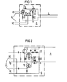
- a two-wire line ZL is connected to a four-wire line VL having a transmitting branch VS and a receiving branch VE Simultaneous decoupling of the two four-wire line branches VS, VE from each other, a transformer-free hybrid circuit G with a two-wire line terminating impedance Z2, R2 which at least approximates the characteristic impedance of the two-wire line ZL is provided.
- the hybrid G contains first the series connection of a signal current source I, to the control input of which the transmission branch VS of the four-wire line VL leads, and a first ohmic resistor R1; this series connection is the two-wire terminating impedance formed by the series connection of a second ohmic resistor R2, the resistance value of which may be at least approximately twice that of the first ohmic resistor R1, and a further impedance Z2.
- the two one terminals of the two ohmic resistors R1, R2 are directly connected to one another and to the one two-wire line core a, at least in terms of alternating current, while the two other terminals of the two ohmic resistors R1, R2 are connected to one another via the series connection of two resistors R3, R4, these two resistances of the same size and at the same time large compared to the first resistor R1 and the second resistor R2.
- the receiving branch VE of the four-wire line VL is connected between the connecting point e of the two resistances R3, R4 and the connecting point a of the two resistors R1, R2.
- the transmission signal current 2i s supplied by the current source I controlled by the transmission branch VS of the four-wire line VL is divided into the two-wire line ZL and the two-wire line termination impedance Z2, R2 to at least approximately equal parts i s ; at the same time flows through the two-wire line terminating impedance Z2, R2 of the received signal current i supplied via the two-wire line ZL from the remote station - not shown in FIG. 1, in principle also provided with a signal current source.
- a voltage occurs at the resistor R2 of the two-wire line termination impedance Z2 + R2, which is composed of a component i e ⁇ R2 proportional to the received signal current and a component i s .R2 proportional to the transmit signal current.
- the ohmic one in series with the signal current source I becomes Resistor R1 only flows through the transmission signal current 2.i s , so that here alone a transmission current-proportional voltage 2 ⁇ i s ⁇ R1 occurs.
- the reception branch VE of the four-wire line VL connected between the connection point a of the two resistors R1, R2 and the connection point e of the two resistances R3, R4 is compared with a mean value proportional to the received signal current between the voltage occurring at the resistor R2 of the two-wire line termination impedance and the resistance Receive signal corresponding to R1 of the current source branch occurring voltage.
- the parallel connection of the two-wire line terminating impedance Z2, R2 and the current source branch I, R1 can also be used as a feeder for a supply current supplied via the two-wire line ZL in the case of a direct current-impermeable two-wire line terminating impedance, so that the signal current source I is supplied by the feed current supplied via the two-wire line ZL.
- the signal current source I can be switched on its control electrode can be formed from the transmission branch VS of the four-wire line VS controlled transistor TI through which the feed current flows, as illustrated in the drawing in FIG. A signal temperature source in the hybrid circuit G according to FIG.
- the field effect transistor TI is a temperature-stable, voltage-resistant field-effect transistor TI, in the example an N-channel junction field-effect transistor, preferably with high steepness, whose source resistance has the mentioned first ohmic resistance R1 with a resistance value of for example 5O ⁇ .
- R1 first ohmic resistance
- the field effect transistor TI can be controlled from the transmission branch VS, for example from a microphone amplifier or a data source, so that the supply current is modulated accordingly and thus a corresponding transmission signal current is produced.
- the two-wire line impedance Z2, R2, which is impermeable to direct current according to FIG. 2, consists of the series connection of said second ohmic resistor R2 of, for example, 100 ⁇ and the further impedance Z2 required for further simulation of the two-wire line impedance, depending on the line type, which is advantageously provided by an RC circuit, if necessary . can be formed by an RC chain break circuit, as is also indicated in Fig.2.
- the control path of a transistor TE in the example of a depletion IG field-effect transistor with an N-channel operating as a simple source follower, at the latter Source resistance via a capacitor, the received signal for the receive branch VE of the four-wire line VL is removed.
- a negative feedback operational amplifier can also be provided without this being shown in the drawing, which has its inverting input at the received signal switching point e and its other input at the switching point a and its output to the receiving branch VE of the four-wire line VL leads; otherwise any remaining effects of the received signal on the signal current source transistor TI are then avoided.
- an adaptive transversal filter F can be provided in parallel with the resistance R3, which feeds an echo compensation signal to the received signal circuit point e to further increase the decoupling between the transmitting branch VS and the receiving branch VE of the four-wire line VL. Since it is known in principle (e.g. from FREQUENCY 28 (1974) 5, 118 ... 122 and 155 ... 161) to eliminate transmission-signal-related interference signals occurring in the receive branch of a hybrid circuit by adding or subtracting compensation signals, one is required here such echo cancellation not to be discussed in more detail.
- a circuit element D through which the supply current supplied via the two-wire line TL flows, is inserted in the supply circuit, to which a local operating voltage U B (for transmit and receive circuits of the four-wire line and for the hybrid circuit itself) can be tapped.
- This circuit element is formed in the circuit arrangement according to FIG. 2 by a zener diode; in deviation from the representation in Figure 2, the Zener diode can also be replaced by a circuit that only draws current when the operating voltage U B has reached an operating voltage setpoint.
- the hybrid circuit according to the invention is not limited to a message transmission using the same method, but can also be used in a transmission system with two-wire line transmission channels separated from one another in terms of time and / or frequency: the hybrid circuit is then with a four-wire line Transmitter branch VS for sending out transmit signal pulses at certain times and / or with a certain focus of their frequency spectrum and a four-wire line branch VE for receiving received signal pulses at other times and / or with another focus - connected to their frequency spectrum.
- the hybrid circuit can be preceded by a chain connection of a speech signal coder, for example given by a delta modulator, and a digital signal transmission circuit for transmitting transmission signal pulses, for example at certain times, and a chain connection of a corresponding one in the reception branch VE of the four-wire line VL Digital signal receiving circuit and a speech signal decoder possibly given by a delta demodulator.
- a speech signal coder for example given by a delta modulator
- a digital signal transmission circuit for transmitting transmission signal pulses, for example at certain times
- a chain connection of a corresponding one in the reception branch VE of the four-wire line VL Digital signal receiving circuit and a speech signal decoder possibly given by a delta demodulator.
- the aforementioned digital signal transmission circuit can, for example, emit pseudo-ternary half-step signal pulses, so-called half-bauded AMI (alternate mark inversion) signal pulses, for which purpose, as is suggested elsewhere (DE-P 29 16 576), may have an instantaneous values of the S e ndesignalimpulse encoded stored and controlled in accordance with the signal output by the speech coder digital signals read only memory, which encoded the corresponding instantaneous values in their Representation supplies a decoder, which forms the corresponding transmission signal pulses.
- pseudo-ternary half-step signal pulses so-called half-bauded AMI (alternate mark inversion) signal pulses, for which purpose, as is suggested elsewhere (DE-P 29 16 576)
- AMI alternate mark inversion
- the digital signal receiving circuit can contain a regenerator as it is known in principle (for example from the Siemens publication "PCM - the pulse code modulation and its application in telecommunications", page 15, figure 21) and in which a clock extractor is used a received bit clock is derived from the received signal pulses, on the basis of which the decision times are defined at which the amplitude decision about the respective status value of the relevant bit is made in the digital signal receiving circuit;
- the digital signal reception circuit can contain a reception signal converter that can be implemented, for example, with a rectifier circuit, which converts the regenerated signals into corresponding ⁇ M or PCM signals.
- the transmit bit clock can, as is suggested elsewhere (DE-AS 29 21 019), be derived from the receive bit clock and be phase-shifted by half a bit period.
- Such circuit details of the transmission branch VS and reception branch VE of the four-wire line VL are, however, no longer shown in the drawing and do not need to be pursued further here, since this is not necessary to understand the invention.
Landscapes
- Engineering & Computer Science (AREA)
- Signal Processing (AREA)
- Computer Networks & Wireless Communication (AREA)
- Cable Transmission Systems, Equalization Of Radio And Reduction Of Echo (AREA)
- Dc Digital Transmission (AREA)
- Mechanical Operated Clutches (AREA)
Priority Applications (1)
| Application Number | Priority Date | Filing Date | Title |
|---|---|---|---|
| AT81103807T ATE3487T1 (de) | 1980-05-23 | 1981-05-18 | Uebertragerfreie gabelschaltung. |
Applications Claiming Priority (2)
| Application Number | Priority Date | Filing Date | Title |
|---|---|---|---|
| DE3019835 | 1980-05-23 | ||
| DE3019835A DE3019835C2 (de) | 1980-05-23 | 1980-05-23 | Übertragerfreie Gabelschaltung |
Publications (2)
| Publication Number | Publication Date |
|---|---|
| EP0040785A1 true EP0040785A1 (fr) | 1981-12-02 |
| EP0040785B1 EP0040785B1 (fr) | 1983-05-18 |
Family
ID=6103195
Family Applications (1)
| Application Number | Title | Priority Date | Filing Date |
|---|---|---|---|
| EP81103807A Expired EP0040785B1 (fr) | 1980-05-23 | 1981-05-18 | Circuit hybride sans transformateur |
Country Status (8)
| Country | Link |
|---|---|
| US (1) | US4418249A (fr) |
| EP (1) | EP0040785B1 (fr) |
| JP (1) | JPS5713825A (fr) |
| AT (1) | ATE3487T1 (fr) |
| CA (1) | CA1171565A (fr) |
| DE (1) | DE3019835C2 (fr) |
| DK (1) | DK151997C (fr) |
| SU (1) | SU1371514A3 (fr) |
Cited By (1)
| Publication number | Priority date | Publication date | Assignee | Title |
|---|---|---|---|---|
| NL1000486C2 (en) * | 1995-06-02 | 1996-12-03 | Nederland Ptt | Fork circuit for twisted pair transmission line |
Families Citing this family (6)
| Publication number | Priority date | Publication date | Assignee | Title |
|---|---|---|---|---|
| US6243446B1 (en) | 1997-03-11 | 2001-06-05 | Inline Connections Corporation | Distributed splitter for data transmission over twisted wire pairs |
| US5010399A (en) | 1989-07-14 | 1991-04-23 | Inline Connection Corporation | Video transmission and control system utilizing internal telephone lines |
| JPH0375370U (fr) * | 1989-11-27 | 1991-07-29 | ||
| DE19828337A1 (de) * | 1998-06-25 | 1999-12-30 | Bosch Gmbh Robert | Telekommunikationsgerät |
| US6532279B1 (en) | 1999-06-11 | 2003-03-11 | David D. Goodman | High-speed data communication over a residential telephone wiring network |
| US8385538B2 (en) * | 2008-12-10 | 2013-02-26 | Utc Fire & Security Americas Corporation, Inc. | Method, system, and apparatus for a differential transformer-free hybrid circuit |
Citations (6)
| Publication number | Priority date | Publication date | Assignee | Title |
|---|---|---|---|---|
| DE1963507A1 (de) * | 1969-12-18 | 1971-06-24 | Licentia Gmbh | UEbertragerlose Gabelschaltung zur Verbindung einer Zweidraht- und einer Vierdrahtleitung |
| DE2159149A1 (de) * | 1971-11-29 | 1973-06-07 | Siemens Ag | Schaltungsanordnung fuer zentralgespeiste teilnehmerstationen mit eine widerstandsbruecke enthaltenden sprechschaltungen |
| AT354529B (de) * | 1976-02-20 | 1979-01-10 | Deutsche Telephonwerk Kabel | Schaltungsanordnung fuer eine unsymmetrische elektronische gabelanordnung, insbesondere fuer fernsprechanlagen |
| DE2807785A1 (de) * | 1978-02-23 | 1979-08-30 | Siemens Ag | Digitales nachrichtenuebertragungssystem |
| US4174470A (en) * | 1978-10-10 | 1979-11-13 | Bell Telephone Laboratories, Incorporated | Electronic hybrid |
| DE1762849B2 (de) * | 1968-09-10 | 1980-02-07 | Telefunken Patentverwertungsgesellschaft Mbh, 7900 Ulm | Übertragerfreie Brückenschaltung |
Family Cites Families (10)
| Publication number | Priority date | Publication date | Assignee | Title |
|---|---|---|---|---|
| DE1762849U (de) | 1957-12-20 | 1958-03-06 | Hermann Schwend K G | Musterkarte. |
| US3453395A (en) * | 1965-12-01 | 1969-07-01 | Gen Electric | Solid-state hybrid |
| US3529099A (en) * | 1967-05-10 | 1970-09-15 | Itt | Telephone subset with resistive hybrid network |
| GB1241037A (en) * | 1968-07-26 | 1971-07-28 | Telefongyar | A circuit arrangement |
| US3751602A (en) * | 1971-08-13 | 1973-08-07 | Bell Telephone Labor Inc | Loudspeaking telephone |
| BE792329A (fr) * | 1971-12-09 | 1973-06-06 | Int Standard Electric Corp | Circuit de transmission electronique pour poste telephonique |
| FR2404344A1 (fr) * | 1977-09-27 | 1979-04-20 | Jeumont Schneider | Equipement electronique d'abonne, a circuit de conversion deux fils-quatre fils, pour central telephonique |
| US4228323A (en) * | 1979-01-31 | 1980-10-14 | Bell Telephone Laboratories, Incorporated | Variable loop length compensated barrier circuit |
| DE2916576C3 (de) * | 1979-04-24 | 1981-12-10 | Siemens AG, 1000 Berlin und 8000 München | Digital-Fernmeldesystem für Zweidraht-Getrenntlage-Betrieb |
| DE2921019C2 (de) * | 1979-05-23 | 1981-06-19 | Siemens AG, 1000 Berlin und 8000 München | Digital-Fernmeldesystem mit mindestens einem Vierdrahtleitungsabschnitt |
-
1980
- 1980-05-23 DE DE3019835A patent/DE3019835C2/de not_active Expired
-
1981
- 1981-05-12 JP JP7028181A patent/JPS5713825A/ja active Granted
- 1981-05-18 AT AT81103807T patent/ATE3487T1/de not_active IP Right Cessation
- 1981-05-18 EP EP81103807A patent/EP0040785B1/fr not_active Expired
- 1981-05-21 CA CA000377972A patent/CA1171565A/fr not_active Expired
- 1981-05-22 SU SU813290849A patent/SU1371514A3/ru active
- 1981-05-22 US US06/266,210 patent/US4418249A/en not_active Expired - Fee Related
- 1981-05-22 DK DK226381A patent/DK151997C/da active
Patent Citations (6)
| Publication number | Priority date | Publication date | Assignee | Title |
|---|---|---|---|---|
| DE1762849B2 (de) * | 1968-09-10 | 1980-02-07 | Telefunken Patentverwertungsgesellschaft Mbh, 7900 Ulm | Übertragerfreie Brückenschaltung |
| DE1963507A1 (de) * | 1969-12-18 | 1971-06-24 | Licentia Gmbh | UEbertragerlose Gabelschaltung zur Verbindung einer Zweidraht- und einer Vierdrahtleitung |
| DE2159149A1 (de) * | 1971-11-29 | 1973-06-07 | Siemens Ag | Schaltungsanordnung fuer zentralgespeiste teilnehmerstationen mit eine widerstandsbruecke enthaltenden sprechschaltungen |
| AT354529B (de) * | 1976-02-20 | 1979-01-10 | Deutsche Telephonwerk Kabel | Schaltungsanordnung fuer eine unsymmetrische elektronische gabelanordnung, insbesondere fuer fernsprechanlagen |
| DE2807785A1 (de) * | 1978-02-23 | 1979-08-30 | Siemens Ag | Digitales nachrichtenuebertragungssystem |
| US4174470A (en) * | 1978-10-10 | 1979-11-13 | Bell Telephone Laboratories, Incorporated | Electronic hybrid |
Non-Patent Citations (1)
| Title |
|---|
| Nachrichtentechnische Zeitschrift, 22. Jahrgang, heft 11, November 1969, Berlin M. TABOR "Verbesserung der Homogenitat in Fernsprechnetzen Durch Transistor-Gebelschaltungen" seiten 668-671 + seite 670, linke spalte, zeilen 7-51; bild 5 + * |
Cited By (1)
| Publication number | Priority date | Publication date | Assignee | Title |
|---|---|---|---|---|
| NL1000486C2 (en) * | 1995-06-02 | 1996-12-03 | Nederland Ptt | Fork circuit for twisted pair transmission line |
Also Published As
| Publication number | Publication date |
|---|---|
| CA1171565A (fr) | 1984-07-24 |
| JPS6342977B2 (fr) | 1988-08-26 |
| DE3019835C2 (de) | 1983-12-01 |
| EP0040785B1 (fr) | 1983-05-18 |
| DK226381A (da) | 1981-11-24 |
| JPS5713825A (en) | 1982-01-23 |
| ATE3487T1 (de) | 1983-06-15 |
| DE3019835A1 (de) | 1981-12-03 |
| DK151997B (da) | 1988-01-18 |
| DK151997C (da) | 1988-07-18 |
| SU1371514A3 (ru) | 1988-01-30 |
| US4418249A (en) | 1983-11-29 |
Similar Documents
| Publication | Publication Date | Title |
|---|---|---|
| EP0050748B1 (fr) | Poste d'abonné, analogique/numérique | |
| DE3850201T2 (de) | Leitungsschnittstellenschaltung. | |
| DE3783803T2 (de) | Sender fuer s-bus-schnittstelle in einem dienstintegrierenden digitalnetz (isdn). | |
| DE2535900A1 (de) | Gabelschaltung | |
| DE3115892A1 (de) | "transformatorlose zweidraht-/vierdrahtgabelschaltung" | |
| DE2736136A1 (de) | Signaluebertragungsnetzwerk | |
| EP0040785B1 (fr) | Circuit hybride sans transformateur | |
| DE2826017A1 (de) | Datenfernverarbeitungsgeraet | |
| EP0448753B1 (fr) | Convertisseur deux-fils-quatre-fils | |
| EP0016472B1 (fr) | Dispositif à connexion de bifurcation pour transition de deux à quatre conducteurs dans les système de multiplexage par partage du temps | |
| DE2346984C3 (fr) | ||
| DE2111706C3 (de) | Schaltungsanordnung für eine Fernsprech-Vermittlungsanlage mit Pulsphasenmodulation | |
| DE2517977C2 (de) | Konferenzschaltung in einer Zeitmultiplexvermittlungsanlage | |
| DE4308783C1 (de) | Schaltungsanordnung zur Übertragung nachrichtentechnischer Signale | |
| DE2728854A1 (de) | Doppelt gerichtetes sprachsignal- steuergeraet | |
| EP0037518B1 (fr) | Circuit hybride sans transformateur | |
| EP0467367B1 (fr) | Circuit d'interface de ligne d'abonné pour la connexion d'une ligne d'abonné pour la transmission de signaux analogiques d'abonné à un central téléphonique numérique à multiplexage temporel | |
| DE3019882C2 (de) | Übertragerfreie Gabelschaltung | |
| DE2812198C2 (de) | Zeitmultiplex-Fernmeldesystem zum Verbinden von Zweidrahtleitungskreisen | |
| DE2628852B1 (de) | Gabelschaltung zur zweidraht-vollduplex-uebertragung von digitalsignalen | |
| AT401839B (de) | Schaltungsanordnung zum komplexen leitungsabschluss einer an eine kommunikationseinrichtung angeschlossene zweidrahtleitung | |
| EP0101610B1 (fr) | Circuit hybride actif avec dissipation de puissance réduite | |
| DE2314116C3 (de) | System zur Übertragung von Datensignalen | |
| DE963526C (de) | Sendeanordnung zur Signaluebertragung auf Fernsprechleitungen | |
| AT336091B (de) | Zeitmultiplex-fernsprechanlage |
Legal Events
| Date | Code | Title | Description |
|---|---|---|---|
| PUAI | Public reference made under article 153(3) epc to a published international application that has entered the european phase |
Free format text: ORIGINAL CODE: 0009012 |
|
| AK | Designated contracting states |
Designated state(s): AT BE CH FR GB IT NL SE |
|
| 17P | Request for examination filed |
Effective date: 19811028 |
|
| ITF | It: translation for a ep patent filed | ||
| GRAA | (expected) grant |
Free format text: ORIGINAL CODE: 0009210 |
|
| AK | Designated contracting states |
Designated state(s): AT BE CH FR GB IT LI NL SE |
|
| REF | Corresponds to: |
Ref document number: 3487 Country of ref document: AT Date of ref document: 19830615 Kind code of ref document: T |
|
| ET | Fr: translation filed | ||
| PLBE | No opposition filed within time limit |
Free format text: ORIGINAL CODE: 0009261 |
|
| STAA | Information on the status of an ep patent application or granted ep patent |
Free format text: STATUS: NO OPPOSITION FILED WITHIN TIME LIMIT |
|
| 26N | No opposition filed | ||
| PGFP | Annual fee paid to national office [announced via postgrant information from national office to epo] |
Ref country code: NL Payment date: 19890531 Year of fee payment: 9 |
|
| PGFP | Annual fee paid to national office [announced via postgrant information from national office to epo] |
Ref country code: CH Payment date: 19900824 Year of fee payment: 10 |
|
| PG25 | Lapsed in a contracting state [announced via postgrant information from national office to epo] |
Ref country code: NL Effective date: 19901201 |
|
| NLV4 | Nl: lapsed or anulled due to non-payment of the annual fee | ||
| PGFP | Annual fee paid to national office [announced via postgrant information from national office to epo] |
Ref country code: GB Payment date: 19910423 Year of fee payment: 11 |
|
| PGFP | Annual fee paid to national office [announced via postgrant information from national office to epo] |
Ref country code: AT Payment date: 19910424 Year of fee payment: 11 |
|
| PGFP | Annual fee paid to national office [announced via postgrant information from national office to epo] |
Ref country code: SE Payment date: 19910522 Year of fee payment: 11 |
|
| PGFP | Annual fee paid to national office [announced via postgrant information from national office to epo] |
Ref country code: FR Payment date: 19910527 Year of fee payment: 11 Ref country code: BE Payment date: 19910527 Year of fee payment: 11 |
|
| ITTA | It: last paid annual fee | ||
| PG25 | Lapsed in a contracting state [announced via postgrant information from national office to epo] |
Ref country code: LI Effective date: 19910531 Ref country code: CH Effective date: 19910531 |
|
| REG | Reference to a national code |
Ref country code: CH Ref legal event code: PL |
|
| PG25 | Lapsed in a contracting state [announced via postgrant information from national office to epo] |
Ref country code: GB Effective date: 19920518 Ref country code: AT Effective date: 19920518 |
|
| PG25 | Lapsed in a contracting state [announced via postgrant information from national office to epo] |
Ref country code: SE Effective date: 19920519 |
|
| PG25 | Lapsed in a contracting state [announced via postgrant information from national office to epo] |
Ref country code: BE Effective date: 19920531 |
|
| BERE | Be: lapsed |
Owner name: SIEMENS A.G. BERLIN UND MUNCHEN Effective date: 19920531 |
|
| GBPC | Gb: european patent ceased through non-payment of renewal fee |
Effective date: 19920518 |
|
| PG25 | Lapsed in a contracting state [announced via postgrant information from national office to epo] |
Ref country code: FR Effective date: 19930129 |
|
| REG | Reference to a national code |
Ref country code: FR Ref legal event code: ST |
|
| EUG | Se: european patent has lapsed |
Ref document number: 81103807.4 Effective date: 19921204 |