EP0040810A2 - Ressort à friction - Google Patents
Ressort à friction Download PDFInfo
- Publication number
- EP0040810A2 EP0040810A2 EP81103873A EP81103873A EP0040810A2 EP 0040810 A2 EP0040810 A2 EP 0040810A2 EP 81103873 A EP81103873 A EP 81103873A EP 81103873 A EP81103873 A EP 81103873A EP 0040810 A2 EP0040810 A2 EP 0040810A2
- Authority
- EP
- European Patent Office
- Prior art keywords
- lubricant
- friction spring
- spring according
- housing
- friction
- Prior art date
- Legal status (The legal status is an assumption and is not a legal conclusion. Google has not performed a legal analysis and makes no representation as to the accuracy of the status listed.)
- Granted
Links
Images


Classifications
-
- B—PERFORMING OPERATIONS; TRANSPORTING
- B61—RAILWAYS
- B61G—COUPLINGS; DRAUGHT AND BUFFING APPLIANCES
- B61G11/00—Buffers
- B61G11/02—Buffers with metal springs
- B61G11/04—Buffers with metal springs with helical springs
- B61G11/06—Buffers with metal springs with helical springs arranged to damp each other by mutual friction
-
- F—MECHANICAL ENGINEERING; LIGHTING; HEATING; WEAPONS; BLASTING
- F16—ENGINEERING ELEMENTS AND UNITS; GENERAL MEASURES FOR PRODUCING AND MAINTAINING EFFECTIVE FUNCTIONING OF MACHINES OR INSTALLATIONS; THERMAL INSULATION IN GENERAL
- F16F—SPRINGS; SHOCK-ABSORBERS; MEANS FOR DAMPING VIBRATION
- F16F13/00—Units comprising springs of the non-fluid type as well as vibration-dampers, shock-absorbers, or fluid springs
- F16F13/02—Units comprising springs of the non-fluid type as well as vibration-dampers, shock-absorbers, or fluid springs damping by frictional contact between the spring and braking means
Definitions
- the invention relates to a friction spring which consists essentially of within a spring housing, e.g. a sleeve buffer, arranged inner and outer rings is formed, these rings each interacting via conical contact surfaces and using a lubricant, preferably grease.
- a friction spring which consists essentially of within a spring housing, e.g. a sleeve buffer, arranged inner and outer rings is formed, these rings each interacting via conical contact surfaces and using a lubricant, preferably grease.
- the spring housing generally consists of two telescopically guided housing parts, each with a base plate for supporting the corresponding end of the spring.
- the sealing body consists of two shells held on the wall of the outer housing part and a sealing means, for example a ring or cord, is embedded in these shells and bears against the wall of the inner housing part. This sealant can be replaced without having to disassemble the spring case.
- a sealed spring housing is provided, according to a next embodiment of the invention it is provided that the lubricant is under pressure and that the spring housing contains a volume-compressible pressure compensation means, preferably made of polyurethane foam. This ensures a particularly uniform distribution of the lubricant regardless of the installation position and the load condition of the friction spring. Because of the volume-compressible pressure compensation means, there is practically no increase in the pressure for the lubricant during the impact process, so that the characteristic curve of the friction spring remains virtually unchanged. In addition, the pressure - parallel to the biasing force of the friction spring - advantageously ensures that the spring housing is returned to the starting position after the impact force has been absorbed.
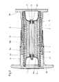
- the aforementioned spring housing is designed as a sleeve buffer for rail vehicles and accordingly consists of an outer housing part 8 and an inner housing part 9, which are telescopically guided and each provided with a base plate 8b or 9b.
- the friction spring is supported under prestress against the base plates 8b and 9b, the extension of the housing parts 8 and 9 being limited by a slotted ring 8d welded to the collar of the inner housing part 9 and welded to the open end of the outer housing part 8 remaining a slide bush 13 receives.
- the rings 1 and 2 of the friction spring are combined by hat-shaped pull pots 6 and a central screw bolt 5 shown in FIGS. 1 to 3 to form an already preloaded, easy-to-use spring column.
- this seal 7 is located in the area of the passage of the bolt 5 through the respective pull pot 6, a seal 7, which prevents the lubricant 3 from escaping from the space inside the friction spring.
- this seal 7 is arranged in a holder 6d which is connected to the pulling pot 6 by welding; Such a holder 6d can also be integrally formed on the pull pot 6.
- 5 shows a seal 7 which is fastened in a form-fitting manner to the central bore 6a of the pull pot 6 via a groove 7a at its end on the draft pot side.
- the special embodiment according to FIG. 3 requires a sealed spring housing 8, 9, for example via the sealing body 10 shown in FIG. 1, because in this case the lubricant 3 fills the remaining housing 8, 9 in addition to the space inside the friction spring and under pressure stands. This ensures a particularly uniform distribution of the lubricant 3 regardless of the installation position and the load condition of the friction spring.
- the grooves 8c and 9c shown in FIG. 3 in the base plates 8b and 9b of the housing parts 8 and 9 as well as bores 6e in the pulling pots 6 also serve for uniform filling with the lubricant 3 via a valve 12 arranged in the base plate 9b.
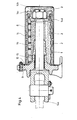
- the connecting device for rail vehicles shown in FIG. 4 in connection with the friction spring forms an encapsulated spring housing for this spring via the housing part 8 and the housing part 9 provided at the same time as a support bearing for a pull rod 14 and the sealing body 10, a bushing 15 and a bellows 16 seal the area where the tie rod 14 passes through the housing part 9.
- a bushing 15 and a bellows 16 seal the area where the tie rod 14 passes through the housing part 9.
- Fig. 1 in the space enclosed by the rings 1 and 2 of the friction spring and also in the housing part 8 an additional amount of lubricant 3 for the spring.
Landscapes
- Engineering & Computer Science (AREA)
- Mechanical Engineering (AREA)
- General Engineering & Computer Science (AREA)
- Springs (AREA)
- Mechanical Operated Clutches (AREA)
- Braking Arrangements (AREA)
- Devices For Conveying Motion By Means Of Endless Flexible Members (AREA)
- Arc-Extinguishing Devices That Are Switches (AREA)
Priority Applications (1)
| Application Number | Priority Date | Filing Date | Title |
|---|---|---|---|
| AT81103873T ATE10391T1 (de) | 1980-05-24 | 1981-05-20 | Reibungsfeder. |
Applications Claiming Priority (2)
| Application Number | Priority Date | Filing Date | Title |
|---|---|---|---|
| DE19803020026 DE3020026A1 (de) | 1980-05-24 | 1980-05-24 | Reibungsfeder |
| DE3020026 | 1980-05-24 |
Publications (3)
| Publication Number | Publication Date |
|---|---|
| EP0040810A2 true EP0040810A2 (fr) | 1981-12-02 |
| EP0040810A3 EP0040810A3 (en) | 1982-05-26 |
| EP0040810B1 EP0040810B1 (fr) | 1984-11-21 |
Family
ID=6103301
Family Applications (1)
| Application Number | Title | Priority Date | Filing Date |
|---|---|---|---|
| EP81103873A Expired EP0040810B1 (fr) | 1980-05-24 | 1981-05-20 | Ressort à friction |
Country Status (9)
| Country | Link |
|---|---|
| US (1) | US4428565A (fr) |
| EP (1) | EP0040810B1 (fr) |
| AT (1) | ATE10391T1 (fr) |
| CS (1) | CS221295B2 (fr) |
| DD (1) | DD159101A1 (fr) |
| DE (2) | DE3020026A1 (fr) |
| PL (1) | PL231162A1 (fr) |
| RO (1) | RO82165A (fr) |
| YU (1) | YU79781A (fr) |
Cited By (2)
| Publication number | Priority date | Publication date | Assignee | Title |
|---|---|---|---|---|
| EP2924172A1 (fr) | 2014-03-28 | 2015-09-30 | Delmag GmbH & Co. KG | Marteau batteur |
| CN112360917A (zh) * | 2020-09-24 | 2021-02-12 | 北京京港地铁有限公司 | 一种用于轨道交通的减震装置 |
Families Citing this family (14)
| Publication number | Priority date | Publication date | Assignee | Title |
|---|---|---|---|---|
| US4756512A (en) * | 1986-12-15 | 1988-07-12 | Miner Enterprises, Inc. | Heavy off-road large vehicle suspension strut |
| DE4030869A1 (de) * | 1990-09-29 | 1992-04-02 | Suspa Compart Ag | Reibungsdaempfer |
| US5746394A (en) * | 1995-03-15 | 1998-05-05 | The Boeing Company | Method and apparatus for damping high frequency vibrations generated by landing gear brake applications |
| US6357612B1 (en) | 1997-04-11 | 2002-03-19 | Asf-Keystone, Inc. | Rail car cushioning device and method for positioning same |
| US6279765B1 (en) * | 1998-01-20 | 2001-08-28 | Asf-Keystone, Inc. | Railcar cushioning device with internal spring |
| US6199708B1 (en) | 1999-03-05 | 2001-03-13 | Asf-Keystone, Inc. | Railcar cushioning device with internal elastomeric spring |
| US6244577B1 (en) * | 1999-07-12 | 2001-06-12 | Enidine Incorporated | Double acting mechanical shock absorber |
| US6513800B1 (en) * | 2001-07-10 | 2003-02-04 | Enidine Inc. | Mechanical double acting shock isolator |
| US7090207B2 (en) * | 2003-02-24 | 2006-08-15 | Dqp Llc | Single-end-mount seismic isolator |
| US7882902B2 (en) * | 2006-11-17 | 2011-02-08 | Weatherford/Lamb, Inc. | Top drive interlock |
| US8733744B2 (en) * | 2011-08-11 | 2014-05-27 | Miner Elastomer Products Corporation | Multipiece cushioning assembly for a telescoping shock absorbing assembly |
| DE102016118218B4 (de) | 2016-09-27 | 2022-06-30 | Bombardier Transportation Gmbh | Schienenfahrzeug mit Kupplungsvorrichtung und Verfahren zur Montage eines Schienenfahrzeugs |
| DE102019218494A1 (de) * | 2019-11-28 | 2021-06-02 | Thyssenkrupp Ag | Federaufnahme, Verfahren zur Herstellung einer Federaufnahme, Schwingungsdämpfer und Niveaueinstellvorrichtung |
| CN116905980A (zh) * | 2023-05-17 | 2023-10-20 | 西南石油大学 | 一种轴向,横向和扭转力阻尼器 |
Family Cites Families (18)
| Publication number | Priority date | Publication date | Assignee | Title |
|---|---|---|---|---|
| DE563194C (de) * | 1933-09-15 | Wilhelm Wurl | Eisenbahn-Huelsenpuffer | |
| DE878452C (de) | 1951-04-01 | 1953-06-01 | Wilhelm Wichard | Staubschutz fuer Ringfedern |
| DE1822759U (de) * | 1960-09-26 | 1960-12-01 | Phoenix Gummiwerke Ag | Zylindrische aus zwei konzentrischen baelgen bestehende staubdichtung. |
| DE1146708B (de) * | 1961-10-26 | 1963-04-04 | Oskar E Peter | Ringfeder |
| US3164263A (en) | 1962-08-27 | 1965-01-05 | Railway Transport Inst | Draft gear for automatic couplers of railway rolling stock |
| DE1882759U (de) * | 1962-12-15 | 1963-11-14 | Mann & Hummel Filter | Oelbadluftfilter fuer brennkraftmaschinen, kompressoren und sonstige luftansaugende maschinen. |
| DE1286818B (de) * | 1967-06-08 | 1969-01-09 | Ringfeder Gmbh | Reibungsfeder |
| DE1978054U (de) * | 1967-11-10 | 1968-02-01 | Hemscheidt Maschf Hermann | Hydraulischer mehrrohr-schwingungsdaempfer. |
| DE1775663C3 (de) | 1968-09-06 | 1976-01-02 | Fichtel & Sachs Ag, 8720 Schweinfurt | Schwingungsdämpfer, insbesondere mit einer zwischen Kolbenstangenende und Zylinder eingespannten Schraubenfeder |
| DD99908A3 (fr) * | 1971-11-10 | 1973-09-05 | ||
| DE2641593C3 (de) * | 1976-09-16 | 1980-06-19 | Ringfeder Gmbh, 4150 Krefeld | Verfahren zum Befullen des Druckraumes einer hydraulischen Feder- und Dampfungsvorrichtung |
| DE2657836A1 (de) * | 1976-12-21 | 1978-06-22 | Ringfeder Gmbh | Vorrichtung zur federnden aufnahme von stosskraeften |
| DE2708367A1 (de) * | 1977-02-26 | 1978-09-14 | Ringfeder Gmbh | Vorrichtung zur federnden aufnahme von stosskraeften |
| US4174098A (en) * | 1978-07-03 | 1979-11-13 | Ace Controls, Inc. | Shock absorber and mounting means therefor |
| DE2918091A1 (de) * | 1979-05-04 | 1980-11-13 | Ringfeder Gmbh | Reibungsfeder, insbesondere fuer huelsenpuffer oder zug- und stossvorrichtungen von mittelpufferkupplungen von schienenfahrzeugen |
| DE2918092A1 (de) * | 1979-05-04 | 1980-11-13 | Ringfeder Gmbh | Vorrichtung zur federnden aufnahme von kraeften, insbesondere fuer eine mittelpufferkupplung von schienenfahrzeugen |
| DE2918095A1 (de) * | 1979-05-04 | 1980-11-13 | Ringfeder Gmbh | Vorrichtung zur federnden aufnahme von kraeften, insbesondere fuer eine mittelpufferkupplung von schienenfahrzeugen |
| DE2946296C2 (de) * | 1979-11-16 | 1984-04-26 | Ringfeder Gmbh, 4150 Krefeld | Zugeinrichtung für Schienenfahrzeuge |
-
1980
- 1980-05-24 DE DE19803020026 patent/DE3020026A1/de not_active Withdrawn
-
1981
- 1981-03-26 YU YU00797/81A patent/YU79781A/xx unknown
- 1981-05-14 PL PL23116281A patent/PL231162A1/xx unknown
- 1981-05-20 DE DE8181103873T patent/DE3167284D1/de not_active Expired
- 1981-05-20 AT AT81103873T patent/ATE10391T1/de not_active IP Right Cessation
- 1981-05-20 EP EP81103873A patent/EP0040810B1/fr not_active Expired
- 1981-05-21 CS CS813785A patent/CS221295B2/cs unknown
- 1981-05-21 DD DD81230157A patent/DD159101A1/de unknown
- 1981-05-22 US US06/266,356 patent/US4428565A/en not_active Expired - Fee Related
- 1981-05-23 RO RO81104388A patent/RO82165A/fr unknown
Cited By (3)
| Publication number | Priority date | Publication date | Assignee | Title |
|---|---|---|---|---|
| EP2924172A1 (fr) | 2014-03-28 | 2015-09-30 | Delmag GmbH & Co. KG | Marteau batteur |
| US9752295B2 (en) | 2014-03-28 | 2017-09-05 | Delmag Gmbh & Co. Kg | Pile hammer |
| CN112360917A (zh) * | 2020-09-24 | 2021-02-12 | 北京京港地铁有限公司 | 一种用于轨道交通的减震装置 |
Also Published As
| Publication number | Publication date |
|---|---|
| DD159101A1 (de) | 1983-02-16 |
| RO82165A (fr) | 1983-07-07 |
| US4428565A (en) | 1984-01-31 |
| EP0040810B1 (fr) | 1984-11-21 |
| ATE10391T1 (de) | 1984-12-15 |
| DE3020026A1 (de) | 1981-12-10 |
| EP0040810A3 (en) | 1982-05-26 |
| DE3167284D1 (en) | 1985-01-03 |
| YU79781A (en) | 1983-12-31 |
| PL231162A1 (fr) | 1982-01-04 |
| RO82165B (ro) | 1983-06-30 |
| CS221295B2 (en) | 1983-04-29 |
Similar Documents
| Publication | Publication Date | Title |
|---|---|---|
| EP0040810A2 (fr) | Ressort à friction | |
| DE69425855T2 (de) | Einzelstück-Abdichtungsvorrichtung durch eine geschmierte Führung für hydraulische Stossdämpfer | |
| DE69200806T2 (de) | Vorrichtung zur Dämpfung von Schwingungen. | |
| DE10305386B3 (de) | Blow-off-Ventil für einen hydraulischen Stoßdämpfer | |
| DE69517368T3 (de) | Kompaktlager und versteifter Lagerzapfen | |
| EP1533541B1 (fr) | Amortisseur de vibrations avec amortissement dépendant de l'amplitude | |
| DE112010005137B4 (de) | Hydraulischer Stoßdämpfer | |
| DE3004307A1 (de) | Selbstpumpendes hydropneumatisches teleskop-feder-daempferelement mit innerer niveauregelung | |
| DE10315645B4 (de) | Hydraulisch dämpfendes Gummibuchsenlager für vertikale Montage | |
| DE916738C (de) | Selbstschmierendes Kapillarlager | |
| EP1870265A1 (fr) | Dispositif de ressort | |
| DE2116623A1 (de) | Kreiselbrecher mit hydraulischer Verstellung und hydropneumatischer Überlastsicherung | |
| DE2328962A1 (de) | Ausgleichseinrichtung | |
| DE60208259T2 (de) | Schwingungsdämpfer mit einer schwimmenden Kolbenstangenführung | |
| DE102012002806A1 (de) | Federbein und Gehäuse eines Federbeins | |
| DE3414821C2 (de) | Dichtungsanordnung | |
| DE7826323U1 (de) | Rollenmeissel | |
| DE69611937T2 (de) | Teleskopdämpfer mit einem laminatkanal | |
| DE3300771C1 (de) | Gasdruckdämpfer in Zweirohr-Teleskop-Bauart | |
| EP1573224A1 (fr) | Palier d'appui d'un element amortisseur de vibrations | |
| DE10228454A1 (de) | Kolben-Zylinderaggregat, insbesondere Schwingungsdämpfer | |
| EP1342922B1 (fr) | Accumulateur de pression | |
| DE102011084475A1 (de) | Achsschenkel oder ein Schwenklager einer Fahrzeug-Achse | |
| DE2924940C2 (de) | Lager für ein axial verschiebbares, um seine Längsachse verdrehbares und allseitig schwenkbares zylindrisches Kraftübertragungsglied | |
| DE3301774A1 (de) | Kraftfahrzeug-vorderachsbein |
Legal Events
| Date | Code | Title | Description |
|---|---|---|---|
| PUAI | Public reference made under article 153(3) epc to a published international application that has entered the european phase |
Free format text: ORIGINAL CODE: 0009012 |
|
| 17P | Request for examination filed |
Effective date: 19810601 |
|
| AK | Designated contracting states |
Designated state(s): AT DE FR SE |
|
| PUAL | Search report despatched |
Free format text: ORIGINAL CODE: 0009013 |
|
| AK | Designated contracting states |
Designated state(s): AT DE FR SE |
|
| GRAA | (expected) grant |
Free format text: ORIGINAL CODE: 0009210 |
|
| AK | Designated contracting states |
Designated state(s): AT DE FR SE |
|
| REF | Corresponds to: |
Ref document number: 10391 Country of ref document: AT Date of ref document: 19841215 Kind code of ref document: T |
|
| REF | Corresponds to: |
Ref document number: 3167284 Country of ref document: DE Date of ref document: 19850103 |
|
| ET | Fr: translation filed | ||
| PLBE | No opposition filed within time limit |
Free format text: ORIGINAL CODE: 0009261 |
|
| STAA | Information on the status of an ep patent application or granted ep patent |
Free format text: STATUS: NO OPPOSITION FILED WITHIN TIME LIMIT |
|
| 26N | No opposition filed | ||
| PGFP | Annual fee paid to national office [announced via postgrant information from national office to epo] |
Ref country code: AT Payment date: 19860528 Year of fee payment: 6 |
|
| PG25 | Lapsed in a contracting state [announced via postgrant information from national office to epo] |
Ref country code: AT Effective date: 19870520 |
|
| PG25 | Lapsed in a contracting state [announced via postgrant information from national office to epo] |
Ref country code: SE Effective date: 19870521 |
|
| PGFP | Annual fee paid to national office [announced via postgrant information from national office to epo] |
Ref country code: FR Payment date: 19890410 Year of fee payment: 9 |
|
| PGFP | Annual fee paid to national office [announced via postgrant information from national office to epo] |
Ref country code: DE Payment date: 19890524 Year of fee payment: 9 |
|
| PG25 | Lapsed in a contracting state [announced via postgrant information from national office to epo] |
Ref country code: FR Effective date: 19910131 |
|
| PG25 | Lapsed in a contracting state [announced via postgrant information from national office to epo] |
Ref country code: DE Effective date: 19910201 |
|
| REG | Reference to a national code |
Ref country code: FR Ref legal event code: ST |
|
| EUG | Se: european patent has lapsed |
Ref document number: 81103873.6 Effective date: 19880601 |