EP0040847A2 - Vorrichtung für Druck-Kompensation - Google Patents
Vorrichtung für Druck-Kompensation Download PDFInfo
- Publication number
- EP0040847A2 EP0040847A2 EP81104018A EP81104018A EP0040847A2 EP 0040847 A2 EP0040847 A2 EP 0040847A2 EP 81104018 A EP81104018 A EP 81104018A EP 81104018 A EP81104018 A EP 81104018A EP 0040847 A2 EP0040847 A2 EP 0040847A2
- Authority
- EP
- European Patent Office
- Prior art keywords
- pressure
- chamber
- piston
- drill bit
- compensating
- Prior art date
- Legal status (The legal status is an assumption and is not a legal conclusion. Google has not performed a legal analysis and makes no representation as to the accuracy of the status listed.)
- Granted
Links
Images


Classifications
-
- F—MECHANICAL ENGINEERING; LIGHTING; HEATING; WEAPONS; BLASTING
- F16—ENGINEERING ELEMENTS AND UNITS; GENERAL MEASURES FOR PRODUCING AND MAINTAINING EFFECTIVE FUNCTIONING OF MACHINES OR INSTALLATIONS; THERMAL INSULATION IN GENERAL
- F16C—SHAFTS; FLEXIBLE SHAFTS; ELEMENTS OR CRANKSHAFT MECHANISMS; ROTARY BODIES OTHER THAN GEARING ELEMENTS; BEARINGS
- F16C33/00—Parts of bearings; Special methods for making bearings or parts thereof
- F16C33/30—Parts of ball or roller bearings
- F16C33/66—Special parts or details in view of lubrication
- F16C33/6603—Special parts or details in view of lubrication with grease as lubricant
- F16C33/6622—Details of supply and/or removal of the grease, e.g. purging grease
-
- E—FIXED CONSTRUCTIONS
- E21—EARTH OR ROCK DRILLING; MINING
- E21B—EARTH OR ROCK DRILLING; OBTAINING OIL, GAS, WATER, SOLUBLE OR MELTABLE MATERIALS OR A SLURRY OF MINERALS FROM WELLS
- E21B10/00—Drill bits
- E21B10/08—Roller bits
- E21B10/22—Roller bits characterised by bearing, lubrication or sealing details
- E21B10/24—Roller bits characterised by bearing, lubrication or sealing details characterised by lubricating details
-
- F—MECHANICAL ENGINEERING; LIGHTING; HEATING; WEAPONS; BLASTING
- F16—ENGINEERING ELEMENTS AND UNITS; GENERAL MEASURES FOR PRODUCING AND MAINTAINING EFFECTIVE FUNCTIONING OF MACHINES OR INSTALLATIONS; THERMAL INSULATION IN GENERAL
- F16N—LUBRICATING
- F16N17/00—Lubrication of machines or apparatus working under extreme conditions
-
- F—MECHANICAL ENGINEERING; LIGHTING; HEATING; WEAPONS; BLASTING
- F16—ENGINEERING ELEMENTS AND UNITS; GENERAL MEASURES FOR PRODUCING AND MAINTAINING EFFECTIVE FUNCTIONING OF MACHINES OR INSTALLATIONS; THERMAL INSULATION IN GENERAL
- F16C—SHAFTS; FLEXIBLE SHAFTS; ELEMENTS OR CRANKSHAFT MECHANISMS; ROTARY BODIES OTHER THAN GEARING ELEMENTS; BEARINGS
- F16C2352/00—Apparatus for drilling
Definitions
- the present invention is related to an automatic denth compensating system and the incorporation of the automatic depth compensating system as an improvement in a rotary drill bit and more particularly, to an automatic depth compensating system which has at least one pressure compensating device for changing the pressure in the interior of a volume in response to pressure changes in the environment surrounding the volume and a pressure surge compensating device which compensates for positive and negative pressure surges when the pressure within the volume change is relative to the environment. Furthermore, the present invention is more particularly directed to a rotary drill bit which includes the improvement of this type of automatic depth compensating system.
- pressue compensators have beer used.
- An examnle of a pressure compensator can be found in U.S. Patent No.4 154 312 which is directed to the Barnetche bit, this patent being incorporated herein by reference.
- a daphragm is positioned between the interior and exterior of the downhole device in order to equalize the pressure between the volume inside the drill bit and the environment.
- a simple niston in a cylinder has been used instead of the bellows. This type of pressure compensator reduces the pressure differential to 0.
- pressure comnensators such as that disclosed in the Barnetche bit patent, have the disadvantage that at best. they nroduce equal nressure between the inside of the drill bit and the environment. Furthermore, generally due to hysteresis and viscosity of internal lubricants, the internal pressure is less than the external pressure. This means that at the seal in the case of the differential pressure being 0, the seal tends to dry out since no lubricant is added to the seal faces. In the case of negative internal pressure even though it is small, there will be a small amount of leakage in which the aggressive external environment will enter the seal faces thereby accelerating seal wear. Furthermore, the harmful elements of this aggressive environment will also have a damaging effect on the internal parts of the drill bit such as the bearings
- a drill bit lubrication system using a differential piston is shown in U.S. patert No. 3 244 459 .
- the differential piston includes a cylinder of two different diameters with a piston having different diameters in each of the portions of the cylinder.
- This type of differential piston will a predetermined percentage greater than the exteral pressure
- the differential piston device of Ortloff has two significant disadvantages. First since the internal pressure is a predetermined percentage gretear than the external pressure, at extreme operating pressures which are often found in well drilling such as the type with which it is used, although the percentage may be small, the absolute pressure differential between the internal and external pressure is very large.
- the present invention is directed to an automatic depth compensating system for controlling the pressure in a volume in response to pressure changes in the environment adjacent to the volume.
- the system comprises at least one pressure comnensating means positioned between the volume and the environment for changing the pressure in the volume in response to changes in the environment and a nressure surge compensating device positioned between the volume and the environment for compensating for positive and negative pressure surges when the pressure in the volume changes relative to the pressure in the environment.
- the compensating device comprises a cylinder which includes a first bore having a first cross-sectional area and a second bore'having a second cross-sectional area, the first and second bores being axially aligned.
- a first piston having a first head surface area is slidably positioned in the first bore and a second piston having a second head surface area is slidablv positioned in the second bore.
- the first and second head surface areas are different and the first and second pistons are coupled together so that they move together.
- a spring is positioned in the second bore for anplying a force to the second piston to bias the second piston in a dirertion towards the first bore.
- the spring provides a force which acts in concert with the force of the internal pressure on the second piston to thereby reduce the absolute nressure differential between the interior and exterior of the volume therebv enabling the device to operate under extreme external pressures.
- the surge compensating device comprises a cylinder and a piston in the cylinder for forming a chamber therein.
- a first check valve is positioned between the chamber and the volume with the first check valve opening to carrv fluid from the chamber to the volume when the pressure in the volume is lower than the pressure in the chamber by a first predetermined amount.
- a second check valve is positioned between the chamber and the volume with the second check valve opening to carry fluid from the volume to the chamber when the pressure in the volume is higher than the pressure in the chamber by a second Predetermined amount.
- the first predeterminedpressuredifferential is less than the second predetermined pressure differential. pressure in the chamber by a second predetermined amount.
- the first predetermined pressure differential is less than still another important aspect of the present invention is the incorporation of the automatic depth compensating svstem seal lubricating device in downhole devices which operate in aggressive environments and Furthermore, to incorporate the automatic depth compensating svstem and seal lubricating device as an improvement in a rotary drill bit having a solid cutting head such as, for example. in a Barnetche bit.
- FIG. 1 illustration in diagrammatic form, an apparatus such as a downhole device which is formed from two parts 1 and 3 the parts 1 and 3 enclose an interior space 5 which contains elements associated with the device (not shown) and a lubricant (not shown )shown)also contained within the volume or space 5 by means of a seal 5 such as an o-ring.
- Theo-ring 7 seals the volume 5from the surrounding environmentwhich in a downhole situation is an aggressive or damaging environment.
- the pressure compensatig system of the pesent invention includes a pressure compensatig device 9and a pressure surge compensatig device 11. Lubricant is placed in the interior 5 through a valve 13.
- Depth compensating device 9 is formed by a cylinder 13 having an upper portion 13a ard a lower portion 13b.
- the upper notion 13a has a diameter da and the lower portion 13b has a diameter db which is less than da.
- a piston 15 is positioned within the cylinder 13, the piston 15 having an upper head portion 15a having a diameter da located within the upper portion of the cylinder 13a.
- the piston 15 has a second head portion 15b of a diameter db which is positioned within the lower portion of the cylinder 13b.
- Piston head 15a is sealed. by means of an 0-ring seal 17a and piston head 15b is sealed by means of an 0-ring seal 17b.
- the face of the piston head 15a is exposed to the environment while the bottom face of the piston head 15b is exnosed to the lubricant in the interior of the volume or space 5.
- the upper portion of the cylinder 13 has stops 13c which nrovide upper limits for the movement of the niston 15.
- Piston heads 15a and 15b are coupled by member 15c which has a cross-sectional area which is negligible with respect to the cross-sectional area of the piston heads. This avoids air compression in the space between the piston heads 15a and 15b.
- a helical spring 19 is positioned between the bottom face of piston head 15b and stops 13d of the cylinder 13.
- the spring 19 biases the piston 15 in the direction of upper portion 13a of the cylinder 13
- a check valve 20 is placed in the bottom of pressure compensating device 9 to prevent movement of the piston 15 in response to a relatively small pressure decrease in the bore hole or increase in the interior space.
- piston 15 in response to a relatively small pressur decrease in the bore hole or increase in the interior space.
- the interior space 5 is pre-filled with a lubricant and is a+ atmospheric pressure. The lubricant is held within the space 5and is prevented from entering the space 21 between the upper and lower niston heads 15a and 15b by means of the seal 17b.
- Lubricant is added through inlets 16a, 16b and 16c until piston 15 is moved upwards and contacts stops 13c and piston ?5 contacts stops 23c. This ensures proner filling of the space 5.
- inlets l6a, 16b and 16c are closed using a nlug or similar device. As the device is lowered down a bore hole, for example, the space 21 between the piston heads 15a and 15b is sealed by means of seal 17a.
- the force Fa is opposed bv two forces; one, the force on piston head 15b as a result of the internal pressure within the space 5 and the other of the force of spring 19.
- the force from the internal pressure within the space 5 is where db is the diameter of the piston head 15b.
- the force of the spring is Fs.
- the internal pressure PI is always greater than the internal pressure PE.
- the internal pressure is greater than the external pressure by a factor equal to the square of the ratio of the diameter minus a number related to the spring force.
- the spring force Fs varies as a function of the compression of the spring.
- the external pressure will always be a constant percentage of the internal pressure. For example, if the square of the ratio of the diameters is then the external pressure will always be 0.9 or 90% of the internal pressure.
- the device When the device is used in drilling such as well or water well drilling, the device may be used at great depths and the external pressure could be as high as 9,000 psi. The internal pressure would then be 10, 000 nsi. Although, there is compensation for changes in pressure. the absolute difference between the internal and external pressure in the above example is 1 , 000 psi . Thus, the seal 7 would be subjected to a pressure of over 1 , 000 psi. A pressure differential this great could result in a failure of the seal 7.
- Pressure surge compensator 11 comprises a body member 23, the upper nortion of which 23a forms a cylinder with a piston 25 therein. Space 27 below the piston is filled with a lubricant.
- the lower portion 23b of the body 23, has two check valves 29 and 31 therein.
- niston 15 will not begin movement until the drill bit reaches a certain depth and further the movement of piston 15 in pressure compensating device 9 is subjected to a large static frictional force as a result of the seals 17a and 17b.
- a surge in pressure may not be compensated for because of the static friction force.
- the pressure surge compensater 11 provides compensation by means of check valves 29 and 31 for both positive and negative pressure surges.
- check valve 29 selected to open at about a 2 psi pressure differential
- check valve 31 is selected to open at about a 50 psi pressure differential. Since the check valves are not subject to static frictional forces. surges in pressure will be automatically compensated for without the need to overcome the forces of static friction.
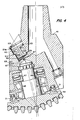
- a pressure compensating and seal lubricating device is illustrated in use with a rotarv drill having a solid conical cutting head similar to that shown in U.S. Patent No. 4 154 312.
- the dnil bit comprises a body 41 and a cutting head or cone 43 rotatably mounted therein.
- the cutting head 43 is supported in the body 41 by means of bearings 45, 47, 49 and 51.
- Pressure compensating devices 53 are positioned in the upper part of the body 41 circumferentially spaced from one another.
- Pressure surge comnensating device 55 is positioned adjacent the pressure comnensating devices 53.
- the pressure compensating devices 53 which is shown in Figure 4 comprises a cylinder 59 having a first bore 59a and a second bore 59b.
- a first piston head 61a is positioned in bore 59a
- a second piston head 61b is positioned in bore 59b, the piston heads 61a and 61b being rigidly connected to each other by a connector 63.
- This differential piston device can, of course, be a single integral element as illustrated.
- Seals 65 form a seal between the piston heads and the cylinder.
- a spring 67 biases the piston 61 in a direction towards bore 59a of the cylinder 59.
- a lubricant is added to the interior of the drill bit body 41 through channel 67 after removing plug 69. This_lubricant lubricates the bearing structure, retaining structure and seals generally indicated at 71.
- the pressure compensation and seal lubrication is accomplished in the manner described above with respect to the previously discussed embodiments.
- the pressure source compensating device 57 is of the type illustrated in Figure 3 with the check valves 29 and 31 facing the interior of the drill bit body 41.
- Each pressure compensating device 53 hasa particular pressure differential at which it initially begins movement and at which it can move no further.
- the point of initial movement is a function of the diameters da and db. the force of static friction and the force of the spring 19
- the noint at which it can move no further is when the spring 19 i s fully compressed.
- the parameters, that is the diameters da and db and the spring 19 can be selected so that the piston onerates in a particular range of pressure differentials.
- the range of operation can be extended. For example, one pressure compensating device 53 may operate in a range of 500-1 .000 psi while a second pressure compensating device may operate in a range of 1,000-2,000 psi.
- the overall range of operation is then 500-2,000 psi. Furthermore, if it is found that because of the operating conditions it is necessary to force larger amounts of lubricant through the seals, the volume of lubricant available can be increased bv increasing the number of pressure comnensating devices. In this situation, all of the pressure compensating devices may operate over the same pressure range but the volume of lubricant available will be increased because the number of pistons is increased. Furthermore; more than two pressure compensating devices can be used ; in order to both expand the range and expand the volume of lubricant displaced by the pi stons.
Landscapes
- Engineering & Computer Science (AREA)
- General Engineering & Computer Science (AREA)
- Mechanical Engineering (AREA)
- Geology (AREA)
- Life Sciences & Earth Sciences (AREA)
- Mining & Mineral Resources (AREA)
- General Life Sciences & Earth Sciences (AREA)
- Fluid Mechanics (AREA)
- Environmental & Geological Engineering (AREA)
- Geochemistry & Mineralogy (AREA)
- Physics & Mathematics (AREA)
- Earth Drilling (AREA)
- Fluid-Pressure Circuits (AREA)
- Drilling And Boring (AREA)
- Electrical Discharge Machining, Electrochemical Machining, And Combined Machining (AREA)
- Auxiliary Devices For Machine Tools (AREA)
- Lifting Devices For Agricultural Implements (AREA)
- Paper (AREA)
Priority Applications (1)
| Application Number | Priority Date | Filing Date | Title |
|---|---|---|---|
| AT81104018T ATE11322T1 (de) | 1980-05-27 | 1981-05-25 | Vorrichtung fuer druck-kompensation. |
Applications Claiming Priority (2)
| Application Number | Priority Date | Filing Date | Title |
|---|---|---|---|
| US06/153,682 US4328873A (en) | 1980-05-27 | 1980-05-27 | Automatic depth compensating system for drill bit lubrication |
| US153682 | 1980-05-27 |
Publications (3)
| Publication Number | Publication Date |
|---|---|
| EP0040847A2 true EP0040847A2 (de) | 1981-12-02 |
| EP0040847A3 EP0040847A3 (en) | 1982-01-20 |
| EP0040847B1 EP0040847B1 (de) | 1985-01-16 |
Family
ID=22548276
Family Applications (1)
| Application Number | Title | Priority Date | Filing Date |
|---|---|---|---|
| EP81104018A Expired EP0040847B1 (de) | 1980-05-27 | 1981-05-25 | Vorrichtung für Druck-Kompensation |
Country Status (8)
| Country | Link |
|---|---|
| US (1) | US4328873A (de) |
| EP (1) | EP0040847B1 (de) |
| JP (1) | JPS5936077B2 (de) |
| AT (1) | ATE11322T1 (de) |
| BR (1) | BR8103281A (de) |
| CA (1) | CA1159443A (de) |
| DE (1) | DE3168271D1 (de) |
| MX (1) | MX154023A (de) |
Cited By (2)
| Publication number | Priority date | Publication date | Assignee | Title |
|---|---|---|---|---|
| WO2012022615A1 (de) * | 2010-08-20 | 2012-02-23 | Schaeffler Technologies Gmbh & Co. Kg | Lager, speziell zur verwendung unter wasser |
| RU2513927C1 (ru) * | 2012-12-03 | 2014-04-20 | Открытое акционерное общество "Волгабурмаш" (ОАО "Волгабурмаш") | Резервуар для смазочной системы бурового шарошечного долота |
Families Citing this family (5)
| Publication number | Priority date | Publication date | Assignee | Title |
|---|---|---|---|---|
| US6802380B2 (en) | 2001-08-31 | 2004-10-12 | Halliburton Energy Services Inc. | Pressure relief system and methods of use and making |
| DE602006011120D1 (de) * | 2006-02-10 | 2010-01-28 | Omni Oil Technologies | Druckausgleichssystem |
| WO2018170038A2 (en) * | 2017-03-14 | 2018-09-20 | Antelope Oil Tool & Mfg. Co., Llc | Expansion chamber |
| CN116577134B (zh) * | 2023-04-24 | 2025-09-09 | 浙江中正岩土技术有限公司 | 一种基于压力补偿的岩土勘测系统 |
| US20260063013A1 (en) * | 2024-08-29 | 2026-03-05 | Halliburton Energy Services, Inc. | Seal energizing systems to maintain seal energization in a downhole well and methods to maintain seal energization in a downhole well |
Family Cites Families (10)
| Publication number | Priority date | Publication date | Assignee | Title |
|---|---|---|---|---|
| US2906504A (en) * | 1958-08-07 | 1959-09-29 | Jersey Prod Res Co | Lubrication of bearings |
| US3303898A (en) * | 1962-11-09 | 1967-02-14 | Mini Petrolului | Bearing sealing and lubricating device |
| US3251634A (en) * | 1963-07-01 | 1966-05-17 | Exxon Production Research Co | Drill bit bearing lubricator |
| US3244459A (en) * | 1963-07-01 | 1966-04-05 | Exxon Production Research Co | Pressure lubricated drill bit bearing |
| US3299973A (en) * | 1964-07-27 | 1967-01-24 | Smith Ind International Inc | Lubrication and sealing of well drilling bit |
| US3847234A (en) * | 1972-06-01 | 1974-11-12 | Reed Tool Co | Pressure relief device for drill bit lubrication system |
| US3844364A (en) * | 1973-10-23 | 1974-10-29 | Dresser Ind | Hydrostatic rock bit lubrication system |
| US3866695A (en) * | 1974-07-01 | 1975-02-18 | Dresser Ind | Bearing Cavity Pressure Maintenance Device For Sealed Bearing Rock Bit |
| US4154312A (en) * | 1977-05-26 | 1979-05-15 | Eduardo Barnetche | Drill bit with single cutting head |
| US4254838A (en) * | 1979-07-24 | 1981-03-10 | Eduardo Barnetche | Automatic depth compensating device |
-
1980
- 1980-05-27 US US06/153,682 patent/US4328873A/en not_active Expired - Lifetime
-
1981
- 1981-04-23 MX MX186981A patent/MX154023A/es unknown
- 1981-05-25 DE DE8181104018T patent/DE3168271D1/de not_active Expired
- 1981-05-25 EP EP81104018A patent/EP0040847B1/de not_active Expired
- 1981-05-25 AT AT81104018T patent/ATE11322T1/de not_active IP Right Cessation
- 1981-05-26 CA CA000378337A patent/CA1159443A/en not_active Expired
- 1981-05-26 BR BR8103281A patent/BR8103281A/pt unknown
- 1981-05-27 JP JP56079474A patent/JPS5936077B2/ja not_active Expired
Cited By (2)
| Publication number | Priority date | Publication date | Assignee | Title |
|---|---|---|---|---|
| WO2012022615A1 (de) * | 2010-08-20 | 2012-02-23 | Schaeffler Technologies Gmbh & Co. Kg | Lager, speziell zur verwendung unter wasser |
| RU2513927C1 (ru) * | 2012-12-03 | 2014-04-20 | Открытое акционерное общество "Волгабурмаш" (ОАО "Волгабурмаш") | Резервуар для смазочной системы бурового шарошечного долота |
Also Published As
| Publication number | Publication date |
|---|---|
| MX154023A (es) | 1987-04-01 |
| BR8103281A (pt) | 1982-02-16 |
| JPS5936077B2 (ja) | 1984-09-01 |
| CA1159443A (en) | 1983-12-27 |
| JPS5712792A (en) | 1982-01-22 |
| EP0040847A3 (en) | 1982-01-20 |
| ATE11322T1 (de) | 1985-02-15 |
| DE3168271D1 (en) | 1985-02-28 |
| US4328873A (en) | 1982-05-11 |
| EP0040847B1 (de) | 1985-01-16 |
Similar Documents
| Publication | Publication Date | Title |
|---|---|---|
| US4335791A (en) | Pressure compensator and lubricating reservoir with improved response to substantial pressure changes and adverse environment | |
| US4254839A (en) | Radial force anti-extrusion device for sealed drill string unit | |
| US9316319B2 (en) | Pressure-balanced floating seal housing assembly and method | |
| US5588491A (en) | Rotating blowout preventer and method | |
| US6250806B1 (en) | Downhole oil-sealed bearing pack assembly | |
| US4359111A (en) | Self compensating seal apparatus | |
| CA2518146C (en) | Bearing assembly for downhole mud motor | |
| US3251634A (en) | Drill bit bearing lubricator | |
| US6003605A (en) | Balanced line tubing retrievable safety valve | |
| US6416225B1 (en) | Bearing assembly for wellbore drilling | |
| US4276946A (en) | Biased lubricant compensator for an earth boring drill bit | |
| CA2102984C (en) | Sealed bearing assembly used in earth drilling | |
| JPS6361471B2 (de) | ||
| US4254838A (en) | Automatic depth compensating device | |
| US4019785A (en) | Drill bit utilizing lubricant thermal expansion and relief valve for pressure control | |
| EP0040847B1 (de) | Vorrichtung für Druck-Kompensation | |
| US12055014B2 (en) | Sealing system for downhole tool | |
| US4577705A (en) | Bellows lubricant pressurizer for sealed bearing rock bits | |
| US4262759A (en) | Combination seal and pressure relief valve for sealed drill string unit | |
| US3419093A (en) | Cutter assembly for well tools | |
| US4552228A (en) | Low pressure differential compensator | |
| US8579046B2 (en) | Pressure compensator for drill bit | |
| US3230019A (en) | Drill bit lubricator | |
| US4402495A (en) | Drill string shock absorber with pressurized lubricant system | |
| GB2064620A (en) | Drill string shock absorber with pressurized lubricant system |
Legal Events
| Date | Code | Title | Description |
|---|---|---|---|
| PUAI | Public reference made under article 153(3) epc to a published international application that has entered the european phase |
Free format text: ORIGINAL CODE: 0009012 |
|
| PUAL | Search report despatched |
Free format text: ORIGINAL CODE: 0009013 |
|
| AK | Designated contracting states |
Designated state(s): AT BE CH DE FR GB IT LU NL SE |
|
| AK | Designated contracting states |
Designated state(s): AT BE CH DE FR GB IT LU NL SE |
|
| TCNL | Nl: translation of patent claims filed | ||
| ITCL | It: translation for ep claims filed |
Representative=s name: DR. ING. A. RACHELI & C. |
|
| TCAT | At: translation of patent claims filed | ||
| 17P | Request for examination filed |
Effective date: 19820703 |
|
| ITF | It: translation for a ep patent filed | ||
| GRAA | (expected) grant |
Free format text: ORIGINAL CODE: 0009210 |
|
| AK | Designated contracting states |
Designated state(s): AT BE CH DE FR GB IT LI LU NL SE |
|
| REF | Corresponds to: |
Ref document number: 11322 Country of ref document: AT Date of ref document: 19850215 Kind code of ref document: T |
|
| REF | Corresponds to: |
Ref document number: 3168271 Country of ref document: DE Date of ref document: 19850228 |
|
| ET | Fr: translation filed | ||
| PG25 | Lapsed in a contracting state [announced via postgrant information from national office to epo] |
Ref country code: LU Free format text: LAPSE BECAUSE OF NON-PAYMENT OF DUE FEES Effective date: 19850531 |
|
| PLBE | No opposition filed within time limit |
Free format text: ORIGINAL CODE: 0009261 |
|
| STAA | Information on the status of an ep patent application or granted ep patent |
Free format text: STATUS: NO OPPOSITION FILED WITHIN TIME LIMIT |
|
| 26N | No opposition filed | ||
| PGFP | Annual fee paid to national office [announced via postgrant information from national office to epo] |
Ref country code: DE Payment date: 19900423 Year of fee payment: 10 |
|
| PGFP | Annual fee paid to national office [announced via postgrant information from national office to epo] |
Ref country code: LU Payment date: 19900425 Year of fee payment: 10 Ref country code: BE Payment date: 19900425 Year of fee payment: 10 |
|
| PGFP | Annual fee paid to national office [announced via postgrant information from national office to epo] |
Ref country code: FR Payment date: 19900430 Year of fee payment: 10 Ref country code: CH Payment date: 19900430 Year of fee payment: 10 |
|
| PGFP | Annual fee paid to national office [announced via postgrant information from national office to epo] |
Ref country code: GB Payment date: 19900502 Year of fee payment: 10 |
|
| PGFP | Annual fee paid to national office [announced via postgrant information from national office to epo] |
Ref country code: SE Payment date: 19900518 Year of fee payment: 10 |
|
| ITTA | It: last paid annual fee | ||
| PGFP | Annual fee paid to national office [announced via postgrant information from national office to epo] |
Ref country code: NL Payment date: 19900531 Year of fee payment: 10 Ref country code: AT Payment date: 19900531 Year of fee payment: 10 |
|
| PG25 | Lapsed in a contracting state [announced via postgrant information from national office to epo] |
Ref country code: GB Effective date: 19910525 Ref country code: AT Effective date: 19910525 |
|
| PG25 | Lapsed in a contracting state [announced via postgrant information from national office to epo] |
Ref country code: SE Effective date: 19910526 |
|
| PG25 | Lapsed in a contracting state [announced via postgrant information from national office to epo] |
Ref country code: LI Effective date: 19910531 Ref country code: CH Effective date: 19910531 Ref country code: BE Effective date: 19910531 |
|
| BERE | Be: lapsed |
Owner name: GONZALEZ EDUARDO BARNETCHE Effective date: 19910531 |
|
| PG25 | Lapsed in a contracting state [announced via postgrant information from national office to epo] |
Ref country code: NL Effective date: 19911201 |
|
| NLV4 | Nl: lapsed or anulled due to non-payment of the annual fee | ||
| GBPC | Gb: european patent ceased through non-payment of renewal fee | ||
| PG25 | Lapsed in a contracting state [announced via postgrant information from national office to epo] |
Ref country code: FR Effective date: 19920131 |
|
| REG | Reference to a national code |
Ref country code: CH Ref legal event code: PL |
|
| REG | Reference to a national code |
Ref country code: CH Ref legal event code: AUV Free format text: DAS OBENGENANNTE PATENT IST, MANGELS BEZAHLUNG DER 11. JAHRESGEBUEHR GELOESCHT WORDEN. |
|
| REG | Reference to a national code |
Ref country code: FR Ref legal event code: ST |
|
| PG25 | Lapsed in a contracting state [announced via postgrant information from national office to epo] |
Ref country code: DE Effective date: 19920501 |
|
| EUG | Se: european patent has lapsed |
Ref document number: 81104018.7 Effective date: 19911209 |