EP0040865B1 - Accouplement articulé pour inclinaison de jet d'eau d'irrigateurs en général - Google Patents
Accouplement articulé pour inclinaison de jet d'eau d'irrigateurs en général Download PDFInfo
- Publication number
- EP0040865B1 EP0040865B1 EP81200445A EP81200445A EP0040865B1 EP 0040865 B1 EP0040865 B1 EP 0040865B1 EP 81200445 A EP81200445 A EP 81200445A EP 81200445 A EP81200445 A EP 81200445A EP 0040865 B1 EP0040865 B1 EP 0040865B1
- Authority
- EP
- European Patent Office
- Prior art keywords
- tubular members
- apex
- ribs
- coupling
- cusp
- Prior art date
- Legal status (The legal status is an assumption and is not a legal conclusion. Google has not performed a legal analysis and makes no representation as to the accuracy of the status listed.)
- Expired
Links
- 230000008878 coupling Effects 0.000 title claims abstract description 24
- 238000010168 coupling process Methods 0.000 title claims abstract description 24
- 238000005859 coupling reaction Methods 0.000 title claims abstract description 24
- 238000004891 communication Methods 0.000 claims abstract description 4
- 238000001125 extrusion Methods 0.000 claims description 6
- 238000007789 sealing Methods 0.000 claims description 3
- 239000007788 liquid Substances 0.000 claims description 2
- 230000002262 irrigation Effects 0.000 description 4
- 238000003973 irrigation Methods 0.000 description 4
- 239000003621 irrigation water Substances 0.000 description 3
- XLYOFNOQVPJJNP-UHFFFAOYSA-N water Substances O XLYOFNOQVPJJNP-UHFFFAOYSA-N 0.000 description 3
- 238000009434 installation Methods 0.000 description 2
- 230000009471 action Effects 0.000 description 1
- 230000008901 benefit Effects 0.000 description 1
- 230000006835 compression Effects 0.000 description 1
- 238000007906 compression Methods 0.000 description 1
- 238000013016 damping Methods 0.000 description 1
- 230000007423 decrease Effects 0.000 description 1
- 239000013013 elastic material Substances 0.000 description 1
- 230000004048 modification Effects 0.000 description 1
- 238000012986 modification Methods 0.000 description 1
- 230000000007 visual effect Effects 0.000 description 1
Images

Classifications
-
- F—MECHANICAL ENGINEERING; LIGHTING; HEATING; WEAPONS; BLASTING
- F16—ENGINEERING ELEMENTS AND UNITS; GENERAL MEASURES FOR PRODUCING AND MAINTAINING EFFECTIVE FUNCTIONING OF MACHINES OR INSTALLATIONS; THERMAL INSULATION IN GENERAL
- F16L—PIPES; JOINTS OR FITTINGS FOR PIPES; SUPPORTS FOR PIPES, CABLES OR PROTECTIVE TUBING; MEANS FOR THERMAL INSULATION IN GENERAL
- F16L27/00—Adjustable joints; Joints allowing movement
- F16L27/08—Adjustable joints; Joints allowing movement allowing adjustment or movement only about the axis of one pipe
- F16L27/0849—Adjustable joints; Joints allowing movement allowing adjustment or movement only about the axis of one pipe the fluid being turned through an angle when passing from one joint element to another
-
- B—PERFORMING OPERATIONS; TRANSPORTING
- B05—SPRAYING OR ATOMISING IN GENERAL; APPLYING FLUENT MATERIALS TO SURFACES, IN GENERAL
- B05B—SPRAYING APPARATUS; ATOMISING APPARATUS; NOZZLES
- B05B15/00—Details of spraying plant or spraying apparatus not otherwise provided for; Accessories
- B05B15/60—Arrangements for mounting, supporting or holding spraying apparatus
- B05B15/65—Mounting arrangements for fluid connection of the spraying apparatus or its outlets to flow conduits
- B05B15/652—Mounting arrangements for fluid connection of the spraying apparatus or its outlets to flow conduits whereby the jet can be oriented
Definitions
- This invention relates to an articulated coupling constructed in such a manner as to allow extremely simple and rapid adjustment of the jet inclination of irrigators when these latter are in operation.
- An articulated coupling is known, of the type shown in US-A-1.067.516 to Gleason, in which the end of a pipe has the form of a spherical, or partly spherical, body portion and receives the spherical head provided at the end of the other pipe, means being provided for the angular adjustment of the two pipes.
- the main object of the present invention is to provide an articulated coupling for irrigators in general, of the type comprising two consecutive first and second tubular members in constant direct communication with each other, having profiled ends arranged to enable them to be mutually adjusted angularly about a diametrical axis of articulation, seal means between said profiled ends, and adjustment device for said two tubular members, and a connecting clamp for the tubular members, so that the coupling by means of a simple and reliable structure, allows simple and rapid adjustment of the jet inclination of the corresponding irrigator even when this latter is in operation, being completely rigid in the transversal plane.
- this object is attained in that said end of said first tubular member is profiled and comprises a cusp-shaped rib having an apex at a diameter of said end, surfaces of said cusp-shaped rib on opposite sides of said apex converging toward said apex and being in opposed facing relation to the similar cusp-shaped rib of said end of said second tubular member, coupling means connecting said tubular members together for pivotal movement with respect to each other about a fixed axis corresponding essentially to said diameter at said apex, from a first position in which surfaces of ribs of the tubular members on one side of the apex engage each other, to a position in which the surfaces of the ribs of the tubular members at the other side of the apex engage each other, deformable seal means adjacent said ends for sealing said ends throughout movement between said first and second positions, and adjustment means externally of and connected between said tubular members for selectively pivoting said tubular members about said axis to any selected position
- Said two curved tubular members 1 are disposed one following the other so that they are in constant communication with each other.
- the pair of tubular members 1 is arranged to define an elbow or curve designed to be connected between an irrigation water feed column and a propelling tube of an irrigator of known type.
- tubular members 1 could be straight to enable them to be connected into said irrigation water feed column, or between the feed column and the elbow which connects this latter to the propelling tube, or again between said elbow and the said propelling tube, or into this latter.
- each curved tubular member 1 is provided with an outer circumferential flange 2 comprising a suitable set of through orthogonal bores and designed to be connected to the corresponding element of the irrigator which is to be equipped with the present invention.
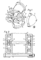
- each tubular member 1 In proximity to said ribs 14, from the surface of each tubular member 1 there branches a pair of parallel brackets 5, disposed symmetrically about the plane in which the pair of tubular members 1 lies.
- a pin 6 is rotatably mounted on the free ends of each pair of brackets 5, and is locked axially relative to said brackets 5 by means of a pair of external Seeger rings 7.
- said pin 6 can comprise an enlarged head at one end, whereas at the other end it is provided with a Seeger ring as stated heretofore.
- the cup-shaped ribs 14 each comprise two flat chamfers which for each of them define a diametrical cusp.
- the two diametrically facing cusps define the diametrical axis of articulation of the articulated joint or coupling.
- Two substantially semicircular rims 3 branch from each rib 14 at the ends of said diameter.
- Said rims 3 define, in pairs, two circular pads at the ends of the axis of articulation and having their centre thereon, these being designed to be enclosed in two lateral covers 9, which ensure the consistency of the articulated joint.
- the two covers 9 are connected together by three tie rods 10 parallel to the axis of articulation, and exert a guiding action on the two parts of the joint by virtue of the fact that their inner wall has a diameter substantially equal to the outer diameter of the rims 3.
- the tie rods 10 clearly keep the two covers 9 in contact with the rims 3 but without damping them together, so as to enable them to move relatively.
- the two rims 3 lie in the same plane, and are each diametrically connected to a base 4 which also lies in said plane and is provided with the same chamfers as the cup-shaped rib 14 from which it branches.
- each tubular member 1 On the inside of the circumferential rib 14 of each tubular member 1, i.e. at the inner mouth thereof, there is a widened shoulder 13 which, in combination with the identical widened shoulder of the other tubular member 1, defines an annular chamber housing a gasket of elastic material 11, as shown in Figure 3, on the outside of which and concentrically thereto there being provided an anti-extrusion ring 12.
- each enlarged shoulder 13 comprises an underlying channel 13a.
- the width of the anti-extrusion ring 12 is less than the corresponding dimension of the annular housing defined by the two underlying channels 13a, so that said ring enables the two tubular members 1 to be mutually adjusted angularly as it can slide inside said annular housing during said adjustment.
- the anti-extrusion ring is preferably rigid, but can also be formed from a flat annular ring of soft rubber.
- the seal member of the invention can also have a configuration of the type shown in Figure 4.
- said seal member is in the form of a double lip gasket 11 a which rests in the annular chamber defined by the enlarged shoulders 13 provided at the facing mouths of the tubular members.
- the underlying channels 13a are not provided, and externally to the double lipped gasket 11 a there is disposed an anti-extrusion ring 12a, the length of which is less than the corresponding dimension of said annular chamber.
- the cross-section of the tubular members 1 need not necessarily be circular, but can be of any other shape.
Landscapes
- Engineering & Computer Science (AREA)
- General Engineering & Computer Science (AREA)
- Mechanical Engineering (AREA)
- Joints Allowing Movement (AREA)
- Supports For Pipes And Cables (AREA)
- Vehicle Body Suspensions (AREA)
- Manipulator (AREA)
- Nozzles (AREA)
- Paper (AREA)
- Cable Accessories (AREA)
- Perforating, Stamping-Out Or Severing By Means Other Than Cutting (AREA)
- Accommodation For Nursing Or Treatment Tables (AREA)
- Catching Or Destruction (AREA)
- Butt Welding And Welding Of Specific Article (AREA)
- Lining Or Joining Of Plastics Or The Like (AREA)
- Harvester Elements (AREA)
Claims (9)
Priority Applications (1)
| Application Number | Priority Date | Filing Date | Title |
|---|---|---|---|
| AT81200445T ATE10416T1 (de) | 1980-05-23 | 1981-04-23 | Gelenkkupplung fuer die neigungsverstellung des wasserstrahles von bewaesserungseinrichtungen. |
Applications Claiming Priority (2)
| Application Number | Priority Date | Filing Date | Title |
|---|---|---|---|
| IT46840/80A IT1141708B (it) | 1980-05-23 | 1980-05-23 | Raccordo snodato particolarmente per la regolazione della inclinazione del getto degli irrigatori in genere |
| IT4684080 | 1980-05-23 |
Publications (2)
| Publication Number | Publication Date |
|---|---|
| EP0040865A1 EP0040865A1 (fr) | 1981-12-02 |
| EP0040865B1 true EP0040865B1 (fr) | 1984-11-28 |
Family
ID=11259501
Family Applications (1)
| Application Number | Title | Priority Date | Filing Date |
|---|---|---|---|
| EP81200445A Expired EP0040865B1 (fr) | 1980-05-23 | 1981-04-23 | Accouplement articulé pour inclinaison de jet d'eau d'irrigateurs en général |
Country Status (8)
| Country | Link |
|---|---|
| US (1) | US4421279A (fr) |
| EP (1) | EP0040865B1 (fr) |
| AT (1) | ATE10416T1 (fr) |
| AU (1) | AU539548B2 (fr) |
| BR (1) | BR8103127A (fr) |
| DE (1) | DE3167398D1 (fr) |
| ES (1) | ES268983Y (fr) |
| IT (1) | IT1141708B (fr) |
Families Citing this family (6)
| Publication number | Priority date | Publication date | Assignee | Title |
|---|---|---|---|---|
| IT1181150B (it) * | 1984-12-21 | 1987-09-23 | Arno Drechsel | Raccordo snodato di tipo telescopico, per la regolazione della inclinazione del getto degli irrigatori in genere, e irrigatore dotato di detto raccordo |
| DE9205712U1 (de) * | 1992-04-29 | 1992-07-09 | IWK Regler und Kompensatoren GmbH, 7513 Stutensee | Kompensator |
| JP2016003669A (ja) * | 2014-06-13 | 2016-01-12 | 株式会社東芝 | 配管部品および配管 |
| US10016776B2 (en) * | 2015-04-07 | 2018-07-10 | Arno Drechsel | Articulated joint for sprinklers |
| US10436370B2 (en) * | 2016-04-20 | 2019-10-08 | Georg Fischer Central Plastics Llc | Pipe elbows and methods of manufacture |
| CN113383697A (zh) * | 2021-07-09 | 2021-09-14 | 陈丽婷 | 一种园林灌溉装置及其灌溉方法 |
Citations (1)
| Publication number | Priority date | Publication date | Assignee | Title |
|---|---|---|---|---|
| US1067516A (en) * | 1911-12-21 | 1913-07-15 | William H Gleeson | High-pressure nozzle. |
Family Cites Families (3)
| Publication number | Priority date | Publication date | Assignee | Title |
|---|---|---|---|---|
| US960899A (en) * | 1909-08-12 | 1910-06-07 | William C Crawford | Pipe-coupling. |
| US3737179A (en) * | 1972-01-20 | 1973-06-05 | Hydrotech Services | Submarine connection for misaligned pipes |
| US4163571A (en) * | 1977-07-18 | 1979-08-07 | Durapipe Limited | Pipe couplings |
-
1980
- 1980-05-23 IT IT46840/80A patent/IT1141708B/it active
-
1981
- 1981-04-03 ES ES1981268983U patent/ES268983Y/es not_active Expired
- 1981-04-21 US US06/256,237 patent/US4421279A/en not_active Expired - Lifetime
- 1981-04-23 EP EP81200445A patent/EP0040865B1/fr not_active Expired
- 1981-04-23 DE DE8181200445T patent/DE3167398D1/de not_active Expired
- 1981-04-23 AT AT81200445T patent/ATE10416T1/de not_active IP Right Cessation
- 1981-05-12 AU AU70463/81A patent/AU539548B2/en not_active Expired
- 1981-05-20 BR BR8103127A patent/BR8103127A/pt unknown
Patent Citations (1)
| Publication number | Priority date | Publication date | Assignee | Title |
|---|---|---|---|---|
| US1067516A (en) * | 1911-12-21 | 1913-07-15 | William H Gleeson | High-pressure nozzle. |
Also Published As
| Publication number | Publication date |
|---|---|
| EP0040865A1 (fr) | 1981-12-02 |
| DE3167398D1 (en) | 1985-01-10 |
| ATE10416T1 (de) | 1984-12-15 |
| ES268983U (es) | 1983-06-16 |
| IT1141708B (it) | 1986-10-08 |
| ES268983Y (es) | 1983-12-16 |
| US4421279A (en) | 1983-12-20 |
| AU7046381A (en) | 1982-01-21 |
| IT8046840A0 (it) | 1980-05-23 |
| AU539548B2 (en) | 1984-10-04 |
| BR8103127A (pt) | 1982-02-09 |
Similar Documents
| Publication | Publication Date | Title |
|---|---|---|
| US5149146A (en) | Double knuckle joint for a wide range orientation of a liquid distributor with respect to a feeder pipe | |
| US5671885A (en) | Nutating sprinkler with rotary shaft and seal | |
| EP0040865B1 (fr) | Accouplement articulé pour inclinaison de jet d'eau d'irrigateurs en général | |
| US2971701A (en) | Universal ball-joint connector | |
| US3965925A (en) | Pinch valve | |
| US5730366A (en) | Oscillating, transverse-axis water sprinkler with see-saw spray arm and twist-positionable nozzles | |
| EP0185901B1 (fr) | Raccord du type télescopique pour l'ajustage de l'angle de trajectoire d'arroseurs et arroseur muni de ce raccord | |
| BR112017021588B1 (pt) | junta articulada para a conexão entre uma linha de fornecimento de líquido e um barril de jato de um irrigador | |
| CN213176855U (zh) | 一种旋转式水路切换结构 | |
| US10619775B2 (en) | Multi-axis rotatable coupling element for a hose or pipe | |
| GB2258023A (en) | Double ball joint | |
| US3994514A (en) | Flexible joint for an overhead irrigation system | |
| US4266730A (en) | Spray device | |
| US4183500A (en) | Control valves | |
| KR102054622B1 (ko) | 배관 굴절 연결 조인트 | |
| CN220060762U (zh) | 一种新型万向调节曲脚 | |
| US4917408A (en) | Adjustable ball fitting for fluid lines | |
| CN216896275U (zh) | 一种卡环及龙头万向接头 | |
| CN213299169U (zh) | 一种角度可调的管件接头 | |
| CN220435748U (zh) | 一种直角液压管接头 | |
| CN221423947U (zh) | 出水口具有球阀结构的分水器 | |
| CN219692584U (zh) | 基于水管与风管并排安装时的异形机械四通 | |
| CN220435717U (zh) | 一种球形万向头双水路软管 | |
| WO1991000722A1 (fr) | Jets de cures thermales reglables | |
| JPH07208669A (ja) | 自在管継手 |
Legal Events
| Date | Code | Title | Description |
|---|---|---|---|
| PUAI | Public reference made under article 153(3) epc to a published international application that has entered the european phase |
Free format text: ORIGINAL CODE: 0009012 |
|
| AK | Designated contracting states |
Designated state(s): AT BE CH DE FR GB IT LU NL SE |
|
| 17P | Request for examination filed |
Effective date: 19820501 |
|
| ITF | It: translation for a ep patent filed | ||
| GRAA | (expected) grant |
Free format text: ORIGINAL CODE: 0009210 |
|
| AK | Designated contracting states |
Designated state(s): AT BE CH DE FR GB IT LI LU NL SE |
|
| REF | Corresponds to: |
Ref document number: 10416 Country of ref document: AT Date of ref document: 19841215 Kind code of ref document: T |
|
| REF | Corresponds to: |
Ref document number: 3167398 Country of ref document: DE Date of ref document: 19850110 |
|
| ET | Fr: translation filed | ||
| PG25 | Lapsed in a contracting state [announced via postgrant information from national office to epo] |
Ref country code: LU Free format text: LAPSE BECAUSE OF NON-PAYMENT OF DUE FEES Effective date: 19850430 |
|
| PLBE | No opposition filed within time limit |
Free format text: ORIGINAL CODE: 0009261 |
|
| STAA | Information on the status of an ep patent application or granted ep patent |
Free format text: STATUS: NO OPPOSITION FILED WITHIN TIME LIMIT |
|
| 26N | No opposition filed | ||
| PGFP | Annual fee paid to national office [announced via postgrant information from national office to epo] |
Ref country code: NL Payment date: 19870430 Year of fee payment: 7 |
|
| PG25 | Lapsed in a contracting state [announced via postgrant information from national office to epo] |
Ref country code: GB Effective date: 19890423 |
|
| PG25 | Lapsed in a contracting state [announced via postgrant information from national office to epo] |
Ref country code: SE Effective date: 19890424 |
|
| PG25 | Lapsed in a contracting state [announced via postgrant information from national office to epo] |
Ref country code: LI Effective date: 19890430 Ref country code: CH Effective date: 19890430 Ref country code: BE Effective date: 19890430 |
|
| BERE | Be: lapsed |
Owner name: DRECHSEL ARNO Effective date: 19890430 |
|
| PG25 | Lapsed in a contracting state [announced via postgrant information from national office to epo] |
Ref country code: NL Effective date: 19891101 |
|
| NLV4 | Nl: lapsed or anulled due to non-payment of the annual fee | ||
| GBPC | Gb: european patent ceased through non-payment of renewal fee | ||
| REG | Reference to a national code |
Ref country code: CH Ref legal event code: PL |
|
| ITTA | It: last paid annual fee | ||
| PGFP | Annual fee paid to national office [announced via postgrant information from national office to epo] |
Ref country code: FR Payment date: 19930414 Year of fee payment: 13 |
|
| PGFP | Annual fee paid to national office [announced via postgrant information from national office to epo] |
Ref country code: AT Payment date: 19930422 Year of fee payment: 13 |
|
| PGFP | Annual fee paid to national office [announced via postgrant information from national office to epo] |
Ref country code: DE Payment date: 19930504 Year of fee payment: 13 |
|
| PG25 | Lapsed in a contracting state [announced via postgrant information from national office to epo] |
Ref country code: AT Effective date: 19940423 |
|
| PG25 | Lapsed in a contracting state [announced via postgrant information from national office to epo] |
Ref country code: FR Effective date: 19941229 |
|
| PG25 | Lapsed in a contracting state [announced via postgrant information from national office to epo] |
Ref country code: DE Effective date: 19950103 |
|
| EUG | Se: european patent has lapsed |
Ref document number: 81200445.5 Effective date: 19900412 |
|
| REG | Reference to a national code |
Ref country code: FR Ref legal event code: ST |