EP0041078A2 - Four à plasma fonctionnant avec des mélanges de gaz - Google Patents
Four à plasma fonctionnant avec des mélanges de gaz Download PDFInfo
- Publication number
- EP0041078A2 EP0041078A2 EP80108157A EP80108157A EP0041078A2 EP 0041078 A2 EP0041078 A2 EP 0041078A2 EP 80108157 A EP80108157 A EP 80108157A EP 80108157 A EP80108157 A EP 80108157A EP 0041078 A2 EP0041078 A2 EP 0041078A2
- Authority
- EP
- European Patent Office
- Prior art keywords
- gas
- plasma torch
- plasma
- additional
- arc
- Prior art date
- Legal status (The legal status is an assumption and is not a legal conclusion. Google has not performed a legal analysis and makes no representation as to the accuracy of the status listed.)
- Granted
Links
- 239000000203 mixture Substances 0.000 title claims abstract description 14
- 239000007789 gas Substances 0.000 claims abstract description 65
- 238000006243 chemical reaction Methods 0.000 claims abstract description 9
- QVGXLLKOCUKJST-UHFFFAOYSA-N atomic oxygen Chemical compound [O] QVGXLLKOCUKJST-UHFFFAOYSA-N 0.000 claims abstract description 7
- 239000001301 oxygen Substances 0.000 claims abstract description 7
- 229910052760 oxygen Inorganic materials 0.000 claims abstract description 7
- UFHFLCQGNIYNRP-UHFFFAOYSA-N Hydrogen Chemical compound [H][H] UFHFLCQGNIYNRP-UHFFFAOYSA-N 0.000 claims abstract description 4
- 239000001257 hydrogen Substances 0.000 claims abstract description 4
- 229910052739 hydrogen Inorganic materials 0.000 claims abstract description 4
- 238000002844 melting Methods 0.000 claims description 14
- 230000008018 melting Effects 0.000 claims description 14
- IJGRMHOSHXDMSA-UHFFFAOYSA-N Atomic nitrogen Chemical compound N#N IJGRMHOSHXDMSA-UHFFFAOYSA-N 0.000 claims description 6
- 229910052757 nitrogen Inorganic materials 0.000 claims description 3
- 239000000956 alloy Substances 0.000 claims description 2
- 229910045601 alloy Inorganic materials 0.000 claims description 2
- 229910052751 metal Inorganic materials 0.000 claims description 2
- 239000002184 metal Substances 0.000 claims description 2
- 150000002739 metals Chemical class 0.000 claims description 2
- 239000000463 material Substances 0.000 abstract description 9
- 230000003628 erosive effect Effects 0.000 abstract description 4
- 239000000654 additive Substances 0.000 abstract description 3
- 230000000996 additive effect Effects 0.000 abstract description 3
- 229920000642 polymer Polymers 0.000 abstract 1
- XKRFYHLGVUSROY-UHFFFAOYSA-N Argon Chemical compound [Ar] XKRFYHLGVUSROY-UHFFFAOYSA-N 0.000 description 4
- 238000010309 melting process Methods 0.000 description 3
- WFKWXMTUELFFGS-UHFFFAOYSA-N tungsten Chemical compound [W] WFKWXMTUELFFGS-UHFFFAOYSA-N 0.000 description 3
- 229910052721 tungsten Inorganic materials 0.000 description 3
- 239000010937 tungsten Substances 0.000 description 3
- 229910052786 argon Inorganic materials 0.000 description 2
- 239000007769 metal material Substances 0.000 description 2
- 230000001590 oxidative effect Effects 0.000 description 2
- RYGMFSIKBFXOCR-UHFFFAOYSA-N Copper Chemical compound [Cu] RYGMFSIKBFXOCR-UHFFFAOYSA-N 0.000 description 1
- 229910000831 Steel Inorganic materials 0.000 description 1
- 239000010406 cathode material Substances 0.000 description 1
- 150000001875 compounds Chemical class 0.000 description 1
- 238000001816 cooling Methods 0.000 description 1
- 239000000498 cooling water Substances 0.000 description 1
- 229910052802 copper Inorganic materials 0.000 description 1
- 239000010949 copper Substances 0.000 description 1
- -1 hydrogen or nitrogen Chemical class 0.000 description 1
- 238000005272 metallurgy Methods 0.000 description 1
- 238000000034 method Methods 0.000 description 1
- RVTZCBVAJQQJTK-UHFFFAOYSA-N oxygen(2-);zirconium(4+) Chemical compound [O-2].[O-2].[Zr+4] RVTZCBVAJQQJTK-UHFFFAOYSA-N 0.000 description 1
- 239000002893 slag Substances 0.000 description 1
- 239000010959 steel Substances 0.000 description 1
- 239000000161 steel melt Substances 0.000 description 1
- 239000000126 substance Substances 0.000 description 1
- XLYOFNOQVPJJNP-UHFFFAOYSA-N water Substances O XLYOFNOQVPJJNP-UHFFFAOYSA-N 0.000 description 1
- 229910001928 zirconium oxide Inorganic materials 0.000 description 1
Images
Classifications
-
- H—ELECTRICITY
- H05—ELECTRIC TECHNIQUES NOT OTHERWISE PROVIDED FOR
- H05H—PLASMA TECHNIQUE; PRODUCTION OF ACCELERATED ELECTRICALLY-CHARGED PARTICLES OR OF NEUTRONS; PRODUCTION OR ACCELERATION OF NEUTRAL MOLECULAR OR ATOMIC BEAMS
- H05H1/00—Generating plasma; Handling plasma
- H05H1/24—Generating plasma
- H05H1/26—Plasma torches
- H05H1/32—Plasma torches using an arc
- H05H1/34—Details, e.g. electrodes, nozzles
- H05H1/3405—Arrangements for stabilising or constricting the arc, e.g. by an additional gas flow
-
- H—ELECTRICITY
- H05—ELECTRIC TECHNIQUES NOT OTHERWISE PROVIDED FOR
- H05H—PLASMA TECHNIQUE; PRODUCTION OF ACCELERATED ELECTRICALLY-CHARGED PARTICLES OR OF NEUTRONS; PRODUCTION OR ACCELERATION OF NEUTRAL MOLECULAR OR ATOMIC BEAMS
- H05H1/00—Generating plasma; Handling plasma
- H05H1/24—Generating plasma
- H05H1/26—Plasma torches
- H05H1/32—Plasma torches using an arc
- H05H1/34—Details, e.g. electrodes, nozzles
- H05H1/3478—Geometrical details
Definitions
- the invention relates to the field of metallurgy, in particular to the melting of metals and alloys in plasma melting furnaces, in which high-power plasma torches are used.
- the high-performance plasma melting torches previously used for melting or remelting metallic materials use technically pure argon as the working gas.
- This working gas ensures on the one hand the protection of the highly heated tungsten cathode inside the burner against burn-off and essentially determines the composition of the furnace atmosphere above the melting material and thus the basic electrical parameters of the plasma column, such as the voltage gradient along the column, the arc voltage and the arc temperature of the plasma column. This resulted in considerations of influencing these electrical arc parameters by adding diatomic gases, e.g. increasing the burner output at constant current by increasing arc voltages or influencing the melting process by including chemical reactions between the melting material and a furnace chamber atmosphere specifically set via the working gas mixture.
- the aim of the invention is to create a plasma burner operated by means of gas mixtures, which works safely at high power.
- the invention has for its object to develop a plasma torch that allows additional gases of different types to be supplied to the plasma arc, in order to determine the electrical arc characteristics and, on the other hand, the chemical flow via the composition of the furnace chamber atmosphere in connection with the high plasma arc temperature To allow reactions between the melting material and the furnace space atmosphere or the melting material, its slag covering and the furnace space atmosphere to take place without neglecting the necessary protection of the highly heated tungsten rod cathode against inadmissible cathode erosion.
- the additional gas is supplied to the plasma torch by means of a ring line from which the gas line pipes lead through the interior of the plasma torch.
- the gas line pipes are arranged symmetrically on a pitch circle around the nozzle opening and inclined at an angle of 35 to 45 ° with respect to the longitudinal axis of the plasma torch.
- the interface between the plasma arc and additional gas is advantageously at a distance of 25.0 to 45.0 mm in front of the surface of the rod-shaped cathode.
- the choice of the additional gas depends on the intended gas influence on the melting process.
- Molecular gases such as hydrogen or nitrogen are selected to increase the voltage gradient along the plasma arc column and thus to increase the performance of the plasma arc with a constant arc current without chemical reaction with the melting material. If a targeted course of chemical reaction of the additional gas with the melting material is to be achieved, oxygen or oxygen-containing gas mixtures are used as the additional gas. Insert bodies can be arranged in the openings of the additional gas outlet in order to achieve a higher speed of the additional gas.
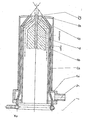
- the accompanying drawing shows a partial longitudinal section of the plasma torch according to the invention: At the connection-side end of the plasma torch known from the basic principle, a ring line 1, on which the gas connection stub 2 is located, is arranged in the area of the cooling water inlet 4.
- a series of gas line pipes 3 lead along the water cooling gap 5 into the interior of the plasma torch.
- the additional gas reaches the nozzle opening 10 of the copper nozzle 6 via the additional gas outlet 9.
- the openings of the additional gas outlets 9 are designed to be inclined to a pitch circle of 35 to 45 ° symmetrically with respect to the longitudinal axis of the plasma torch to the nozzle opening 10. In this way it is achieved that the interface between plasma arc and additional gas in one Ab stood from 25.0 to 45.0 mm in front of the surface of the rod-shaped cathode 7, so that no erosion occurs.
- the cathode 7 itself is cooled via the cathode block 8 and is protected by the argon flow, which is not influenced by the additional gas at this point.
- the choice of the type of additional gas and the amount of gas are determined by the intended influence of gas on the melting process.
- Molecular gases that do not form any chemical compounds, such as hydrogen or nitrogen, with the melting material, for example steel, are selected for the purpose of increasing the voltage gradient along the plasma arc column and thus increasing the performance of the plasma arc with a constant arc current.
- additive gases of a suitable composition are selected.
- Oxygen or O 2 -containing gas mixtures are used to carry out the fresh process.
- the amount of additional gas supplied to the plasma torch is determined by the intended use and adjusted via the gas pressure. To achieve sufficient gas velocities at the additional gas outlets 9, the cross sections of these openings can be varied by arranging insert bodies (not shown in the drawing).
Landscapes
- Physics & Mathematics (AREA)
- Engineering & Computer Science (AREA)
- Plasma & Fusion (AREA)
- Spectroscopy & Molecular Physics (AREA)
- Geometry (AREA)
- Plasma Technology (AREA)
- Vertical, Hearth, Or Arc Furnaces (AREA)
- Manufacture And Refinement Of Metals (AREA)
- Refinement Of Pig-Iron, Manufacture Of Cast Iron, And Steel Manufacture Other Than In Revolving Furnaces (AREA)
- Arc Welding In General (AREA)
- Feeding And Controlling Fuel (AREA)
Applications Claiming Priority (2)
| Application Number | Priority Date | Filing Date | Title |
|---|---|---|---|
| DD221458 | 1980-05-30 | ||
| DD80221458A DD151401A1 (de) | 1980-05-30 | 1980-05-30 | Mittels gasgemischen betriebener plasmabrenner |
Publications (3)
| Publication Number | Publication Date |
|---|---|
| EP0041078A2 true EP0041078A2 (fr) | 1981-12-09 |
| EP0041078A3 EP0041078A3 (en) | 1982-08-11 |
| EP0041078B1 EP0041078B1 (fr) | 1986-03-12 |
Family
ID=5524427
Family Applications (1)
| Application Number | Title | Priority Date | Filing Date |
|---|---|---|---|
| EP80108157A Expired EP0041078B1 (fr) | 1980-05-30 | 1980-12-23 | Four à plasma fonctionnant avec des mélanges de gaz |
Country Status (8)
| Country | Link |
|---|---|
| US (1) | US4469932A (fr) |
| EP (1) | EP0041078B1 (fr) |
| JP (1) | JPS5734699A (fr) |
| AT (1) | ATE18621T1 (fr) |
| DD (1) | DD151401A1 (fr) |
| DE (1) | DE3071496D1 (fr) |
| ES (1) | ES267303Y (fr) |
| YU (1) | YU332980A (fr) |
Families Citing this family (45)
| Publication number | Priority date | Publication date | Assignee | Title |
|---|---|---|---|---|
| US4572942A (en) * | 1982-08-03 | 1986-02-25 | Church John G | Gas-metal-arc welding process |
| FI905886A7 (fi) * | 1989-03-31 | 1990-11-29 | Leningradsky Politekhnichesky Inst | Plasmakäsittelymenetelmä ja -laite |
| US5093602A (en) * | 1989-11-17 | 1992-03-03 | Charged Injection Corporation | Methods and apparatus for dispersing a fluent material utilizing an electron beam |
| US5088997A (en) * | 1990-03-15 | 1992-02-18 | Valleylab, Inc. | Gas coagulation device |
| US5208448A (en) * | 1992-04-03 | 1993-05-04 | Esab Welding Products, Inc. | Plasma torch nozzle with improved cooling gas flow |
| US5686050A (en) * | 1992-10-09 | 1997-11-11 | The University Of Tennessee Research Corporation | Method and apparatus for the electrostatic charging of a web or film |
| US5387842A (en) * | 1993-05-28 | 1995-02-07 | The University Of Tennessee Research Corp. | Steady-state, glow discharge plasma |
| US5669583A (en) * | 1994-06-06 | 1997-09-23 | University Of Tennessee Research Corporation | Method and apparatus for covering bodies with a uniform glow discharge plasma and applications thereof |
| US5938854A (en) * | 1993-05-28 | 1999-08-17 | The University Of Tennessee Research Corporation | Method and apparatus for cleaning surfaces with a glow discharge plasma at one atmosphere of pressure |
| US5955174A (en) * | 1995-03-28 | 1999-09-21 | The University Of Tennessee Research Corporation | Composite of pleated and nonwoven webs |
| CA2197978A1 (fr) | 1995-06-19 | 1996-12-20 | Paul D. Spence | Methodes et electrodes de decharge pour production de plasmas a une pression d'une atmosphere et materiaux ainsi traites |
| US5852927A (en) * | 1995-08-15 | 1998-12-29 | Cohn; Daniel R. | Integrated plasmatron-turbine system for the production and utilization of hydrogen-rich gas |
| US5887554A (en) * | 1996-01-19 | 1999-03-30 | Cohn; Daniel R. | Rapid response plasma fuel converter systems |
| AU7823300A (en) | 1999-06-08 | 2001-01-31 | Bechtel Bwxt Idaho, Llc | Plasma reforming and partial oxidation of hydrocarbon fuel vapor to produce synthesis gas and/or hydrogen gas |
| US20030047146A1 (en) * | 2001-09-10 | 2003-03-13 | Daniel Michael J. | Plasmatron-internal combustion engine system having an independent electrical power source |
| US7014930B2 (en) * | 2002-01-25 | 2006-03-21 | Arvin Technologies, Inc. | Apparatus and method for operating a fuel reformer to generate multiple reformate gases |
| US6959542B2 (en) * | 2002-01-25 | 2005-11-01 | Arvin Technologies, Inc. | Apparatus and method for operating a fuel reformer to regenerate a DPNR device |
| US6976353B2 (en) * | 2002-01-25 | 2005-12-20 | Arvin Technologies, Inc. | Apparatus and method for operating a fuel reformer to provide reformate gas to both a fuel cell and an emission abatement device |
| US7021048B2 (en) * | 2002-01-25 | 2006-04-04 | Arvin Technologies, Inc. | Combination emission abatement assembly and method of operating the same |
| US6651597B2 (en) * | 2002-04-23 | 2003-11-25 | Arvin Technologies, Inc. | Plasmatron having an air jacket and method for operating the same |
| AU2003228608A1 (en) * | 2002-04-24 | 2003-11-10 | Arvin Technologies, Inc. | Apparatus and method for regenerating a particulate filter of an exhaust system of an internal combustion engine |
| US20040020447A1 (en) * | 2002-08-05 | 2004-02-05 | William Taylor | Method and apparatus for advancing air into a fuel reformer by use of an engine vacuum |
| US20040020188A1 (en) * | 2002-08-05 | 2004-02-05 | Kramer Dennis A. | Method and apparatus for generating pressurized air by use of reformate gas from a fuel reformer |
| US20040020191A1 (en) * | 2002-08-05 | 2004-02-05 | Kramer Dennis A. | Method and apparatus for advancing air into a fuel reformer by use of a turbocharger |
| DE10393043T5 (de) * | 2002-08-12 | 2005-08-04 | Arvin Technologies, Inc., Troy | Verfahren und Vorrichtung zum Steuern des Sauerstoff/Kohlenstoff-Verhältnisses eines Kraftstoff-Reformers |
| US20040050345A1 (en) * | 2002-09-17 | 2004-03-18 | Bauer Shawn D. | Fuel reformer control system and method |
| US6758035B2 (en) * | 2002-09-18 | 2004-07-06 | Arvin Technologies, Inc. | Method and apparatus for purging SOX from a NOX trap |
| US20040052693A1 (en) * | 2002-09-18 | 2004-03-18 | Crane Samuel N. | Apparatus and method for removing NOx from the exhaust gas of an internal combustion engine |
| US6702991B1 (en) | 2002-11-12 | 2004-03-09 | Arvin Technologies, Inc. | Apparatus and method for reducing power consumption of a plasma fuel reformer |
| US6715452B1 (en) | 2002-11-13 | 2004-04-06 | Arvin Technologies, Inc. | Method and apparatus for shutting down a fuel reformer |
| US6903259B2 (en) * | 2002-12-06 | 2005-06-07 | Arvin Technologies, Inc. | Thermoelectric device for use with fuel reformer and associated method |
| US6843054B2 (en) * | 2003-01-16 | 2005-01-18 | Arvin Technologies, Inc. | Method and apparatus for removing NOx and soot from engine exhaust gas |
| US20040139730A1 (en) * | 2003-01-16 | 2004-07-22 | William Taylor | Method and apparatus for directing exhaust gas and reductant fluid in an emission abatement system |
| US20040144030A1 (en) * | 2003-01-23 | 2004-07-29 | Smaling Rudolf M. | Torch ignited partial oxidation fuel reformer and method of operating the same |
| US6851398B2 (en) * | 2003-02-13 | 2005-02-08 | Arvin Technologies, Inc. | Method and apparatus for controlling a fuel reformer by use of existing vehicle control signals |
| US20040216378A1 (en) * | 2003-04-29 | 2004-11-04 | Smaling Rudolf M | Plasma fuel reformer having a shaped catalytic substrate positioned in the reaction chamber thereof and method for operating the same |
| US7244281B2 (en) * | 2003-10-24 | 2007-07-17 | Arvin Technologies, Inc. | Method and apparatus for trapping and purging soot from a fuel reformer |
| US7285247B2 (en) * | 2003-10-24 | 2007-10-23 | Arvin Technologies, Inc. | Apparatus and method for operating a fuel reformer so as to purge soot therefrom |
| US7776280B2 (en) * | 2005-05-10 | 2010-08-17 | Emcon Technologies Llc | Method and apparatus for selective catalytic reduction of NOx |
| US7698887B2 (en) * | 2005-06-17 | 2010-04-20 | Emcon Technologies Llc | Method and apparatus for determining local emissions loading of emissions trap |
| US20060283176A1 (en) * | 2005-06-17 | 2006-12-21 | Arvinmeritor Emissions Technologies Gmbh | Method and apparatus for regenerating a NOx trap and a particulate trap |
| US20070095053A1 (en) * | 2005-10-31 | 2007-05-03 | Arvin Technologies, Inc. | Method and apparatus for emissions trap regeneration |
| US8529249B2 (en) * | 2007-09-25 | 2013-09-10 | The United States Of America As Represented By The Administrator Of The National Aeronautics And Space Administration | Flame holder system |
| US9296061B2 (en) | 2013-02-06 | 2016-03-29 | Messer Cutting Systems Inc. | Systems and methods for thermally working a workpiece |
| US9984860B1 (en) * | 2016-11-04 | 2018-05-29 | The United States Of America, As Represented By The Secretary Of The Navy | Apparatus and method for augmenting the volume of atmospheric pressure plasma jets |
Family Cites Families (10)
| Publication number | Priority date | Publication date | Assignee | Title |
|---|---|---|---|---|
| US3106631A (en) * | 1961-04-21 | 1963-10-08 | Union Carbide Corp | Arc torch device |
| US3534388A (en) * | 1968-03-13 | 1970-10-13 | Hitachi Ltd | Plasma jet cutting process |
| US3604889A (en) * | 1969-05-08 | 1971-09-14 | North American Rockwell | Plasma-generating method and means |
| US3865173A (en) * | 1969-05-08 | 1975-02-11 | North American Rockwell | Art of casting metals |
| JPS5220425B1 (fr) * | 1969-09-04 | 1977-06-03 | ||
| US3900762A (en) * | 1971-07-06 | 1975-08-19 | Sheer Korman Associates | Method and apparatus for projecting materials into an arc discharge |
| JPS4834045A (fr) * | 1971-09-06 | 1973-05-15 | ||
| JPS5335544B2 (fr) * | 1972-07-18 | 1978-09-27 | ||
| JPS5116379B2 (fr) * | 1973-07-20 | 1976-05-24 | ||
| GB1487926A (en) * | 1976-10-06 | 1977-10-05 | Rikagaku Kenkyusho | Plasma arc torch operating method |
-
1980
- 1980-05-30 DD DD80221458A patent/DD151401A1/de not_active IP Right Cessation
- 1980-12-23 DE DE8080108157T patent/DE3071496D1/de not_active Expired
- 1980-12-23 AT AT80108157T patent/ATE18621T1/de not_active IP Right Cessation
- 1980-12-23 EP EP80108157A patent/EP0041078B1/fr not_active Expired
- 1980-12-30 YU YU03329/80A patent/YU332980A/xx unknown
-
1981
- 1981-04-30 JP JP6433381A patent/JPS5734699A/ja active Pending
- 1981-05-29 ES ES1981267303U patent/ES267303Y/es not_active Expired
-
1982
- 1982-09-29 US US06/427,374 patent/US4469932A/en not_active Expired - Fee Related
Also Published As
| Publication number | Publication date |
|---|---|
| ATE18621T1 (de) | 1986-03-15 |
| EP0041078B1 (fr) | 1986-03-12 |
| ES267303Y (es) | 1983-09-16 |
| DE3071496D1 (en) | 1986-04-17 |
| US4469932A (en) | 1984-09-04 |
| EP0041078A3 (en) | 1982-08-11 |
| YU332980A (en) | 1983-12-31 |
| JPS5734699A (en) | 1982-02-25 |
| DD151401A1 (de) | 1981-10-14 |
| ES267303U (es) | 1983-03-16 |
Similar Documents
| Publication | Publication Date | Title |
|---|---|---|
| EP0041078B1 (fr) | Four à plasma fonctionnant avec des mélanges de gaz | |
| DE102004049445C5 (de) | Plasmabrenner | |
| DE2912843A1 (de) | Plasmabrenner, plasmabrenneranordnung und verfahren zur plasmaerzeugung | |
| DE4022111A1 (de) | Plasmabrenner fuer uebertragenen lichtbogen | |
| DE1565891A1 (de) | Lichtbogenofen | |
| DE2241972A1 (de) | Verfahren und vorrichtung zur thermischen bearbeitung und verarbeitung hochschmelzender materialien | |
| DD208826A5 (de) | Einrichtung zur herstellung von stahl | |
| DE2511204C2 (de) | Verfahren und Vorrichtung zum Lichtbogenschweißen | |
| DE2429924A1 (de) | Einrichtung zur plasmabearbeitung stromleitender werkstoffe und deren betriebsverfahren | |
| DD259293A5 (de) | Plasmabrenner | |
| DE1940040A1 (de) | Plasmabrenner | |
| EP0122910A1 (fr) | Procédé de fonctionnement d'une installation métallurgique | |
| DE102016219350A1 (de) | Düsenschutzkappe, Lichtbogenplasmabrenner mit dieser Düsenschutzkappe sowie eine Verwendung des Lichtbogenplasmabrenners | |
| DE2256050C3 (de) | Plasmastrahlgenerator | |
| AT257964B (de) | Verfahren zur Reduktion von Metalloxyden | |
| DE102007041329A1 (de) | Plasmabrenner mit axialer Pulvereindüsung | |
| DE2513098A1 (de) | Plasmabrenner fuer lichtbogenofen | |
| DE1440628B2 (de) | Lichtbogenbrenner fuer einen lichtbogenofen | |
| DE2643369A1 (de) | Elektrodeneinheit einer elektrischen entladeeinrichtung | |
| EP0104359B1 (fr) | Procédé et appareil pour la production de gaz chaud | |
| DE2526613A1 (de) | Verfahren und vorrichtung zum erhitzen von gasen | |
| DE1075765B (de) | Lichtbogenbrenner mit nicht abschmelzender Elektrode und gasumhülltem, eingeschnürtem Lichtbogen | |
| DE1070308B (de) | Verfahren zum Schweißen, Schneiden u. dgl. mittels eines gasum'hüllten Lichtbogens unid eines Hilfslichrb'ogens; Zus. z. Anim. U 4034 (DAS 1066676). 3Ü. 10. 57. V. St. Amerika | |
| DE2332070B2 (de) | Verfahren und Vorrichtung zum Plasma-MIG-Schweißen | |
| DE1765564C2 (de) | Verfahren zum Stabilisieren des Lichtbogens eines Lichtbogenbrenners |
Legal Events
| Date | Code | Title | Description |
|---|---|---|---|
| PUAI | Public reference made under article 153(3) epc to a published international application that has entered the european phase |
Free format text: ORIGINAL CODE: 0009012 |
|
| AK | Designated contracting states |
Designated state(s): AT BE CH DE FR GB IT SE |
|
| 17P | Request for examination filed |
Effective date: 19811209 |
|
| PUAL | Search report despatched |
Free format text: ORIGINAL CODE: 0009013 |
|
| AK | Designated contracting states |
Designated state(s): AT BE CH DE FR GB IT SE |
|
| ITF | It: translation for a ep patent filed | ||
| GRAA | (expected) grant |
Free format text: ORIGINAL CODE: 0009210 |
|
| AK | Designated contracting states |
Kind code of ref document: B1 Designated state(s): AT BE CH DE FR GB IT LI SE |
|
| REF | Corresponds to: |
Ref document number: 18621 Country of ref document: AT Date of ref document: 19860315 Kind code of ref document: T |
|
| REF | Corresponds to: |
Ref document number: 3071496 Country of ref document: DE Date of ref document: 19860417 |
|
| ET | Fr: translation filed | ||
| ITTA | It: last paid annual fee | ||
| PLBE | No opposition filed within time limit |
Free format text: ORIGINAL CODE: 0009261 |
|
| STAA | Information on the status of an ep patent application or granted ep patent |
Free format text: STATUS: NO OPPOSITION FILED WITHIN TIME LIMIT |
|
| 26N | No opposition filed | ||
| PGFP | Annual fee paid to national office [announced via postgrant information from national office to epo] |
Ref country code: AT Payment date: 19921021 Year of fee payment: 13 |
|
| PGFP | Annual fee paid to national office [announced via postgrant information from national office to epo] |
Ref country code: FR Payment date: 19921026 Year of fee payment: 13 |
|
| PGFP | Annual fee paid to national office [announced via postgrant information from national office to epo] |
Ref country code: GB Payment date: 19921204 Year of fee payment: 13 |
|
| PGFP | Annual fee paid to national office [announced via postgrant information from national office to epo] |
Ref country code: BE Payment date: 19921209 Year of fee payment: 13 |
|
| PGFP | Annual fee paid to national office [announced via postgrant information from national office to epo] |
Ref country code: SE Payment date: 19921217 Year of fee payment: 13 |
|
| PGFP | Annual fee paid to national office [announced via postgrant information from national office to epo] |
Ref country code: CH Payment date: 19921229 Year of fee payment: 13 |
|
| PGFP | Annual fee paid to national office [announced via postgrant information from national office to epo] |
Ref country code: DE Payment date: 19930224 Year of fee payment: 13 |
|
| REG | Reference to a national code |
Ref country code: CH Ref legal event code: PFA Free format text: SAECHSISCHE EDELSTAHLWERKE GMBH |
|
| REG | Reference to a national code |
Ref country code: FR Ref legal event code: TP |
|
| ITPR | It: changes in ownership of a european patent |
Owner name: CAMBIO RAGIONE SOCIALE;SACHSISCHE EDELSTAHLWERKE G |
|
| PG25 | Lapsed in a contracting state [announced via postgrant information from national office to epo] |
Ref country code: GB Effective date: 19931223 Ref country code: AT Effective date: 19931223 |
|
| PG25 | Lapsed in a contracting state [announced via postgrant information from national office to epo] |
Ref country code: SE Effective date: 19931224 |
|
| PG25 | Lapsed in a contracting state [announced via postgrant information from national office to epo] |
Ref country code: LI Effective date: 19931231 Ref country code: CH Effective date: 19931231 Ref country code: BE Effective date: 19931231 |
|
| BERE | Be: lapsed |
Owner name: SACHSISCHE EDELSTAHLWERKE G.M.B.H. FREITAL Effective date: 19931231 |
|
| GBPC | Gb: european patent ceased through non-payment of renewal fee |
Effective date: 19931223 |
|
| PG25 | Lapsed in a contracting state [announced via postgrant information from national office to epo] |
Ref country code: FR Effective date: 19940831 |
|
| REG | Reference to a national code |
Ref country code: CH Ref legal event code: PL |
|
| PG25 | Lapsed in a contracting state [announced via postgrant information from national office to epo] |
Ref country code: DE Effective date: 19940901 |
|
| REG | Reference to a national code |
Ref country code: FR Ref legal event code: ST |
|
| EUG | Se: european patent has lapsed |
Ref document number: 80108157.1 Effective date: 19940710 |