EP0041252A1 - Conduite de chauffage avec un arrêt de chaleur - Google Patents
Conduite de chauffage avec un arrêt de chaleur Download PDFInfo
- Publication number
- EP0041252A1 EP0041252A1 EP81104131A EP81104131A EP0041252A1 EP 0041252 A1 EP0041252 A1 EP 0041252A1 EP 81104131 A EP81104131 A EP 81104131A EP 81104131 A EP81104131 A EP 81104131A EP 0041252 A1 EP0041252 A1 EP 0041252A1
- Authority
- EP
- European Patent Office
- Prior art keywords
- pipe
- tube
- corrugated
- projections
- smooth
- Prior art date
- Legal status (The legal status is an assumption and is not a legal conclusion. Google has not performed a legal analysis and makes no representation as to the accuracy of the status listed.)
- Granted
Links
- 238000010438 heat treatment Methods 0.000 claims abstract description 19
- 238000009413 insulation Methods 0.000 claims abstract description 13
- 229920002457 flexible plastic Polymers 0.000 claims abstract 5
- 239000008236 heating water Substances 0.000 claims abstract 2
- 238000005253 cladding Methods 0.000 claims description 19
- 239000004033 plastic Substances 0.000 claims description 5
- 229920003023 plastic Polymers 0.000 claims description 5
- 238000007373 indentation Methods 0.000 claims description 3
- 239000000463 material Substances 0.000 abstract description 4
- 239000002131 composite material Substances 0.000 abstract 1
- 238000013461 design Methods 0.000 description 8
- 238000004519 manufacturing process Methods 0.000 description 6
- 238000012546 transfer Methods 0.000 description 6
- 239000004698 Polyethylene Substances 0.000 description 4
- -1 polypropylene Polymers 0.000 description 4
- 229920003020 cross-linked polyethylene Polymers 0.000 description 3
- 239000004703 cross-linked polyethylene Substances 0.000 description 3
- 229920000573 polyethylene Polymers 0.000 description 3
- 239000010865 sewage Substances 0.000 description 3
- 238000012549 training Methods 0.000 description 3
- 238000010276 construction Methods 0.000 description 2
- 238000000034 method Methods 0.000 description 2
- 229920001083 polybutene Polymers 0.000 description 2
- 239000004743 Polypropylene Substances 0.000 description 1
- 238000005452 bending Methods 0.000 description 1
- 230000015572 biosynthetic process Effects 0.000 description 1
- 238000011161 development Methods 0.000 description 1
- 238000003780 insertion Methods 0.000 description 1
- 230000037431 insertion Effects 0.000 description 1
- 238000009434 installation Methods 0.000 description 1
- 238000005259 measurement Methods 0.000 description 1
- 239000002184 metal Substances 0.000 description 1
- 239000004570 mortar (masonry) Substances 0.000 description 1
- 210000002445 nipple Anatomy 0.000 description 1
- 230000035515 penetration Effects 0.000 description 1
- 229920001155 polypropylene Polymers 0.000 description 1
- QQONPFPTGQHPMA-UHFFFAOYSA-N propylene Natural products CC=C QQONPFPTGQHPMA-UHFFFAOYSA-N 0.000 description 1
- 125000004805 propylene group Chemical group [H]C([H])([H])C([H])([*:1])C([H])([H])[*:2] 0.000 description 1
Images

Classifications
-
- F—MECHANICAL ENGINEERING; LIGHTING; HEATING; WEAPONS; BLASTING
- F16—ENGINEERING ELEMENTS AND UNITS; GENERAL MEASURES FOR PRODUCING AND MAINTAINING EFFECTIVE FUNCTIONING OF MACHINES OR INSTALLATIONS; THERMAL INSULATION IN GENERAL
- F16L—PIPES; JOINTS OR FITTINGS FOR PIPES; SUPPORTS FOR PIPES, CABLES OR PROTECTIVE TUBING; MEANS FOR THERMAL INSULATION IN GENERAL
- F16L59/00—Thermal insulation in general
- F16L59/06—Arrangements using an air layer or vacuum
- F16L59/075—Arrangements using an air layer or vacuum the air layer or the vacuum being delimited by longitudinal channels distributed around the circumference of a tube
Definitions
- the invention relates to a thermally insulated heating pipe according to the preamble of claim 1.
- Such heating pipes are becoming increasingly popular for building heating. They are characterized by easy installation under or in the screed, low production costs, good thermal insulation and high mechanical protection. They primarily serve to connect radiators with each other and - primarily - with heating devices or a distributor. Heating pipes with the features of the preamble of claim 1 are e.g. known from German utility model 70 04 901.
- conduits are manufactured by inserting a pre-extruded, sufficiently heat-resistant, smooth-walled inner tube - for example made of polybutene, propylene, cross-linked polyethylene - into a separately extruded corrugated tube made of plastic, in which it is then freely stretchable with play.
- the pipes improved by the invention are distinguished by considerably better thermal insulation.
- the invention intends to further significantly improve the thermal insulation of the conduits according to the preamble of claim 1. This is achieved according to the invention by the design according to the characterizing part of claim 1.
- the design according to the invention not only the heat conduction is reduced to a minimum by contacting the corrugated pipe to the outside. It also largely prevents heat transfer by convection. The penetration of mortar into the outer troughs of the corrugated pipe is prevented.
- the thermal insulation is formed by the cylindrical air jacket between the cladding tube and the inner tube, which is often divided by the corrugated tube and which are held and centered at a distance from the corrugated tube.
- the air jacket is divided by the corrugated tube in the radial direction.
- An air flow in the air jacket is at least very difficult in the axial direction.
- German utility model 78 27 481 to surround sewage pipes of large diameter made of plastic to increase strength with a corrugated pipe which is connected to the sewage pipe at short intervals and not with all inner shaft back on the sewage pipe, but only with, for example, every fourth inner shaft back.
- the corrugated tube can be one with an annular wave back; the wave ridges can also be helical. Normally, the formation with an annular wave back course is preferred.
- the corrugated tube provided with a cladding tube can be produced by a known method. Most simply, this is done by the cladding tube is herumextrudiert around the extruded corrugated pipe by means of a Querspritzko p fes.
- the two extruders for the corrugated tube and the cladding tube can be connected directly one behind the other.
- the protrusions which protrude outwards can be formed, for example, by protrusions protruding outwards from the outer wave troughs or also in that a wave trough is replaced by a wave ridge projecting outwards from the two adjacent normal wave ridges.
- Analog can also the Vor jump arrangement to be formed inwards.
- the training is according to claim 2. This is easier and also affects the Festig - ness of the corrugated pipe less.
- the projections are preferred according to claim 3.
- the production of the tool for the production of the corrugated tube is simpler, at least in the case of a ring-shaped shaft back.
- the axial spacing of the projections from one another an embodiment according to claim 7 is preferred.
- the general rule here is that the axial spacing of the projections from one another can be greater when the projections are arranged inwards than when the projections are arranged outwards, since in the latter the relatively flexible outer cladding tube attaches too easily to the corrugated tube if the axial spacing is too great.
- the protrusions protruding outwards are preferably offset by half an axial pitch of the protrusions compared to the protrusions protruding inwards, since this ensures the least direct heat transfer between the outer cladding tube and the inner smooth tube.
- the heating pipe shown in Fig. 1 has a e.g. polypropylene extruded, smooth-walled inner tube 2, which is surrounded by a corrugated tube 3, for example made of hard polyethylene. To this extent, the heating pipe 1 is known.
- the inside width 1 of the corrugated pipe is increased in the invention, so that the latter is about 4 to 5 mm larger than the outer diameter of the inner pipe 2.
- the flexibility of the inner pipe 2 is at appropriate intervals, for example three outer diameters of the smooth-walled inner tube 2 each have an outer wel lental 4, which in this respect is identical to an inner corrugated ridge, increases inwards so that these inner ring ribs 4, which run at a substantial distance from one another and of reduced clearance, guide the inner tube 2 centrally, which is now corrugated to the other inner corrugated ridges or outer troughs Tube can no longer be applied, whereby the direct heat transfer is significantly reduced.
- the clear width L released by an inner annular rib 4 is only about 2 mm larger than the outer diameter of the smooth tube 2, so that it can be inserted easily even over considerable lengths, if one e.g. at the leading end in an appropriate manner or a guide tip is inserted into this end, the rear end of which continuously merges into the outer circumference of the inner tube 2.
- the majority of the inner tube 2 is kept at a distance from the corrugated tube 3 by the design according to the invention, so that not only heat transfer from tube to tube is prevented, but also a particularly large amount of air Gas insulation room with low thermal conductivity is created.
- the corrugated tube 3 is also overmoulded on the outside with a substantially smooth-walled cladding tube 5, preferably made of polyethylene, which fits snugly against the outer back of the corrugation of the tube 3, which in this embodiment is annular.
- the cladding tube 5 can be glued or welded to the back against which it rests.
- the full contact of the cladding tube 5 is brought about when extruding it onto the corrugated tube 3, in that a certain negative pressure is maintained between the corrugated tube and the cladding tube 5. This technique is well known.
- the cladding tube 5 also makes air circulation between the outer troughs of the corrugated tube 3 and the surroundings of the heating pipe 1 impossible. This further improves the thermal insulation.
- the clear width L within the inner ring projections 4 is still around 10% larger than the outer diameter of the inner tube. With a correspondingly precise production, however, this game can still be considerably reduced. However, it must be ensured that the dimension L is larger than the largest outer diameter of the inner tube 2.
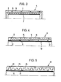
- the heating pipe 6 shown in Fig. 3 has a smooth-walled inner tube 7, for example made of cross-linked polyethylene, which is surrounded by a corrugated tube 8, for example made of non-cross-linked polyethylene, the clear width of which is 2 mm larger than the outer diameter of the inner tube 7.
- an annular outer rib 9 of the corrugated tube 8 is raised on its entire circumference outwards, as shown in the drawing.
- the raised ribs 9 can, for example, project beyond the adjacent normal ribs of the corrugated tube 8 by approximately 10% of the outside diameter of the corrugated tube.
- a sheath tube 10 is extruded around the corrugated tube 8 thus formed, in the same way as in the previously described example, which only bears on the outside of the ribs 9 in the manner shown in FIG. 3. Very good thermal insulation is also produced in this way. With such a design, however, the distance between the projections formed by the ribs 9 must be less in the axial direction than is possible with a design according to FIGS. 1 and 2, since otherwise there is a risk of the relatively soft outer cladding tube 10 being put on, which is expedient also consists of polyethylene, would be too large.
- the heating pipe 12 shown in Fig. 4 has a smooth inner tube 13, for example made of polybutene, which is surrounded by a corrugated tube 14, for example made of PVC.
- the corrugated tube 14 has approximately the same axial spacing as the corrugated tube 8 of the heating pipe 6 increased to the outside, as is the case with the tube 6 formed ring fins 15, against which a cladding tube 16 made of suitable plastic rests so that it is otherwise at a distance from corrugated tube 14 runs, as can be seen from Fig. 4.
- annular rib 17 which reduces the inside width of corrugated tube 14 at the corresponding points, for example by 2 mm, so that the inside width in the area of the inner ring ribs 17 is only 1 to 2 mm larger than the outer diameter of the inner tube 13.
- the line pipe 20 shown in FIG. 5 differs from the pipe 12 essentially only in that in the pipe 20 the axial pitch of the inner and outer ribs 21, 22 of the corrugated pipe 24 is increased to approximately three outer diameters of the inner pipe 23 and in that the inner ribs 21 are offset against the outer ribs 22 in the axial direction by half an axial pitch.
- the path of the heat flowing in the corrugated tube 24 from the inner tube 23 into the cladding tube 25 is very long and the heat transfer is correspondingly low.
- the rings can also be replaced by rows of outer or inner warts, the number of inner warts to replace an inner guide rib 4 or 17, can, of course, be significantly less than the number of outer nipples that are to replace an outer rib 9 or 15.
- the proportion of material in the area of the corrugated cladding tube is to be kept low by the largest possible shaft division.
- the specified outer diameter, the shaft height, the crest compressive strength and the flexibility limit the shaft division upwards.
Landscapes
- Engineering & Computer Science (AREA)
- General Engineering & Computer Science (AREA)
- Mechanical Engineering (AREA)
- Rigid Pipes And Flexible Pipes (AREA)
- Thermal Insulation (AREA)
Applications Claiming Priority (2)
| Application Number | Priority Date | Filing Date | Title |
|---|---|---|---|
| DE19803021045 DE3021045A1 (de) | 1980-06-03 | 1980-06-03 | Waermegedaemmtes leitungsrohr |
| DE3021045 | 1980-06-03 |
Publications (2)
| Publication Number | Publication Date |
|---|---|
| EP0041252A1 true EP0041252A1 (fr) | 1981-12-09 |
| EP0041252B1 EP0041252B1 (fr) | 1983-06-15 |
Family
ID=6103870
Family Applications (1)
| Application Number | Title | Priority Date | Filing Date |
|---|---|---|---|
| EP81104131A Expired EP0041252B1 (fr) | 1980-06-03 | 1981-05-29 | Conduite de chauffage avec un arrêt de chaleur |
Country Status (3)
| Country | Link |
|---|---|
| EP (1) | EP0041252B1 (fr) |
| DE (2) | DE3021045A1 (fr) |
| DK (1) | DK241681A (fr) |
Cited By (6)
| Publication number | Priority date | Publication date | Assignee | Title |
|---|---|---|---|---|
| FR2703431A1 (fr) * | 1993-03-30 | 1994-10-07 | Hutchinson | Gaine d'isolation thermique pour canalisation et son procédé de fabrication. |
| EP0795710A1 (fr) * | 1996-03-15 | 1997-09-17 | Witzenmann GmbH Metallschlauch-Fabrik Pforzheim | Conduite ondulée pour medium sous pression |
| EP1403578A1 (fr) * | 2002-09-30 | 2004-03-31 | Fränkische Rohrwerke Gebr. Kirchner GmbH + Co KG | Tuyau d'un système de chauffage à grande distance |
| FR2859266A1 (fr) * | 2003-09-03 | 2005-03-04 | Tubest Sa | Tubulure a isolation thermique et sonore renforcee |
| EP1681503A1 (fr) * | 2005-01-14 | 2006-07-19 | Tubest Flexible Solutions | Tubulaire rigide à isolation thermique et sonore renforcée |
| ITVI20110045A1 (it) * | 2011-03-10 | 2012-09-11 | Fitt Spa | Assieme tubo per impianti idraulici di piscine, vasche o similari |
Families Citing this family (11)
| Publication number | Priority date | Publication date | Assignee | Title |
|---|---|---|---|---|
| DE3225517C2 (de) * | 1982-07-08 | 1985-01-03 | Felten & Guilleaume Energietechnik GmbH, 5000 Köln | Flexibles Fernwärme-Leitungsrohr mit Anschlußarmaturen als Abzweig- bzw. Hausanschlußschnorchel |
| DE19854521C1 (de) * | 1998-11-26 | 2000-06-08 | Muendener Gummiwerk Gmbh | Isolierte Schlauchleitung |
| DE10150689A1 (de) * | 2001-10-17 | 2003-04-30 | Ina Kuehnendahl | Folie zur Wärmeisolierung eines Produktes |
| US8733405B2 (en) | 2005-03-14 | 2014-05-27 | Advanced Drainage Systems, Inc. | Corrugated pipe with outer layer |
| CA2622692C (fr) | 2007-02-26 | 2015-10-06 | Advanced Drainage Systems, Inc. | Matrice de tuyau double paroi a rapport defini |
| CA2622695C (fr) | 2007-02-26 | 2015-11-03 | Advanced Drainage Systems, Inc. | Appareil et methode de voie d'acheminement de filiere d'extrusion pour tubes |
| US8820801B2 (en) | 2007-11-16 | 2014-09-02 | Advanced Drainage System, Inc. | Multi-wall corrugated pipe couplings and methods |
| US8820800B2 (en) | 2007-11-16 | 2014-09-02 | Advanced Drainage Systems, Inc. | Multi-wall corrugated pipe couplings and methods |
| US8114324B2 (en) | 2008-10-14 | 2012-02-14 | Advanced Drainage Systems, Inc. | Apparatus and method for pressing an outer wall of pipe |
| US7988438B2 (en) | 2008-02-11 | 2011-08-02 | Advanced Drainage Systems, Inc. | Extrusion die vacuum seals |
| US8550807B2 (en) | 2008-05-28 | 2013-10-08 | Advanced Drainage Systems, Inc. | In-mold punch apparatus and methods |
Citations (2)
| Publication number | Priority date | Publication date | Assignee | Title |
|---|---|---|---|---|
| AT326428B (de) * | 1971-12-20 | 1975-12-10 | Kabel Und Metallwerke Getehoff | Rohrleitung zur fortleitung flüssiger oder gasförmiger medien |
| US4037626A (en) * | 1975-09-15 | 1977-07-26 | Standard Oil Company (Indiana) | High strength composite pipe structure having leakproof joints |
Family Cites Families (2)
| Publication number | Priority date | Publication date | Assignee | Title |
|---|---|---|---|---|
| DE7004901U (de) * | 1970-02-12 | 1970-07-23 | Pruefling Dipl Ing Gerhard | Isolierte und geschuetzte flexible rohrleitung aus kunststoff. |
| DE7827481U1 (de) * | 1978-09-15 | 1980-03-20 | Ziegel- Und Kunststoffwerke Heinrich Oltmanns, 2905 Edewecht | Leitungsrohr aus kunststoff |
-
1980
- 1980-06-03 DE DE19803021045 patent/DE3021045A1/de not_active Withdrawn
-
1981
- 1981-05-29 DE DE8181104131T patent/DE3160433D1/de not_active Expired
- 1981-05-29 EP EP81104131A patent/EP0041252B1/fr not_active Expired
- 1981-06-02 DK DK241681A patent/DK241681A/da not_active Application Discontinuation
Patent Citations (2)
| Publication number | Priority date | Publication date | Assignee | Title |
|---|---|---|---|---|
| AT326428B (de) * | 1971-12-20 | 1975-12-10 | Kabel Und Metallwerke Getehoff | Rohrleitung zur fortleitung flüssiger oder gasförmiger medien |
| US4037626A (en) * | 1975-09-15 | 1977-07-26 | Standard Oil Company (Indiana) | High strength composite pipe structure having leakproof joints |
Cited By (7)
| Publication number | Priority date | Publication date | Assignee | Title |
|---|---|---|---|---|
| FR2703431A1 (fr) * | 1993-03-30 | 1994-10-07 | Hutchinson | Gaine d'isolation thermique pour canalisation et son procédé de fabrication. |
| EP0687850A1 (fr) * | 1993-03-30 | 1995-12-20 | Hutchinson | Gaine d'isolation thermique pour canalisation et son procédé de fabrication |
| EP0795710A1 (fr) * | 1996-03-15 | 1997-09-17 | Witzenmann GmbH Metallschlauch-Fabrik Pforzheim | Conduite ondulée pour medium sous pression |
| EP1403578A1 (fr) * | 2002-09-30 | 2004-03-31 | Fränkische Rohrwerke Gebr. Kirchner GmbH + Co KG | Tuyau d'un système de chauffage à grande distance |
| FR2859266A1 (fr) * | 2003-09-03 | 2005-03-04 | Tubest Sa | Tubulure a isolation thermique et sonore renforcee |
| EP1681503A1 (fr) * | 2005-01-14 | 2006-07-19 | Tubest Flexible Solutions | Tubulaire rigide à isolation thermique et sonore renforcée |
| ITVI20110045A1 (it) * | 2011-03-10 | 2012-09-11 | Fitt Spa | Assieme tubo per impianti idraulici di piscine, vasche o similari |
Also Published As
| Publication number | Publication date |
|---|---|
| DE3021045A1 (de) | 1981-12-10 |
| DK241681A (da) | 1981-12-04 |
| EP0041252B1 (fr) | 1983-06-15 |
| DE3160433D1 (en) | 1983-07-21 |
Similar Documents
| Publication | Publication Date | Title |
|---|---|---|
| EP0041252B1 (fr) | Conduite de chauffage avec un arrêt de chaleur | |
| DE10018382B4 (de) | Flexibles Rohr für ein Endoskop | |
| DE1901069A1 (de) | Koaxiale Mehrfachrohranordnung | |
| EP0111248B1 (fr) | Tuyau souple à double paroi | |
| EP0385465B2 (fr) | Procédé de fabrication d'un égout en matière plastique | |
| EP0231446A1 (fr) | Tuyau ondulé en plastique avec manchon incorporé | |
| EP0118945B1 (fr) | Faisceau flexible de tubes et méthode de fabrication de ce faisceau | |
| EP0531750A2 (fr) | Procédé pour le soudage de tuyaux en matière thermoplastique | |
| DE3744510A1 (de) | Rohrverbindungs-element | |
| EP0111271B1 (fr) | Tuyau en plastique, particulièrement pour eaux usées | |
| DE102005037183B3 (de) | Beheizbare Fluidleitung | |
| EP0318434B1 (fr) | Dispositif d'extrusion pour la fabrication d'un tube en plastique | |
| EP2060843A2 (fr) | Tuyau isolé thermiquement et son procédé de fabrication | |
| DE4224743C1 (de) | Kabelschutzrohr | |
| DE202006003590U1 (de) | Beheizbarer Wellschlauch | |
| DE3151845A1 (de) | Wellrohr mit zugentlastung und verfahren zu dessen herstellung aus kunststoff | |
| EP0009105A1 (fr) | Conduite tubulaire en matière plastique | |
| DE2819359C3 (de) | Rohrverbindungsteil aus flexiblem Kunststoff für den Anschluß eines gewellten Rohres | |
| DE2708593A1 (de) | Zusammengesetztes rohr aus verschiedenen kunststoffen und verfahren zu dessen herstellung | |
| EP0985867B1 (fr) | Tuyau ondulé en plastique et combinaison de ce tuyau avec un manchon | |
| EP0583596B1 (fr) | Tuyau de drainage | |
| DE10032308B4 (de) | Wellrohr sowie Verfahren zur Herstellung eines Wellrohres | |
| EP4023919B1 (fr) | Conduite de fluide | |
| AT375496B (de) | Kabelkanalrohranordnung | |
| DE102005031210B4 (de) | Befestigungsvorrichtung für ein Luftleitungssystem |
Legal Events
| Date | Code | Title | Description |
|---|---|---|---|
| PUAI | Public reference made under article 153(3) epc to a published international application that has entered the european phase |
Free format text: ORIGINAL CODE: 0009012 |
|
| 17P | Request for examination filed |
Effective date: 19810827 |
|
| AK | Designated contracting states |
Designated state(s): AT BE CH DE FR LU NL SE |
|
| GRAA | (expected) grant |
Free format text: ORIGINAL CODE: 0009210 |
|
| AK | Designated contracting states |
Designated state(s): DE |
|
| REF | Corresponds to: |
Ref document number: 3160433 Country of ref document: DE Date of ref document: 19830721 |
|
| PLBI | Opposition filed |
Free format text: ORIGINAL CODE: 0009260 |
|
| 26 | Opposition filed |
Opponent name: HEGLER, WILHELM Effective date: 19840309 |
|
| PGFP | Annual fee paid to national office [announced via postgrant information from national office to epo] |
Ref country code: DE Payment date: 19840628 Year of fee payment: 4 |
|
| RDAG | Patent revoked |
Free format text: ORIGINAL CODE: 0009271 |
|
| STAA | Information on the status of an ep patent application or granted ep patent |
Free format text: STATUS: PATENT REVOKED |
|
| 27W | Patent revoked |
Effective date: 19840819 |