EP0041268A1 - Soupape de dégazage pour récipients fermés hermétiquement - Google Patents
Soupape de dégazage pour récipients fermés hermétiquement Download PDFInfo
- Publication number
- EP0041268A1 EP0041268A1 EP81104217A EP81104217A EP0041268A1 EP 0041268 A1 EP0041268 A1 EP 0041268A1 EP 81104217 A EP81104217 A EP 81104217A EP 81104217 A EP81104217 A EP 81104217A EP 0041268 A1 EP0041268 A1 EP 0041268A1
- Authority
- EP
- European Patent Office
- Prior art keywords
- container
- membrane
- valve body
- vent valve
- sealing
- Prior art date
- Legal status (The legal status is an assumption and is not a legal conclusion. Google has not performed a legal analysis and makes no representation as to the accuracy of the status listed.)
- Withdrawn
Links
Images






Classifications
-
- B—PERFORMING OPERATIONS; TRANSPORTING
- B65—CONVEYING; PACKING; STORING; HANDLING THIN OR FILAMENTARY MATERIAL
- B65D—CONTAINERS FOR STORAGE OR TRANSPORT OF ARTICLES OR MATERIALS, e.g. BAGS, BARRELS, BOTTLES, BOXES, CANS, CARTONS, CRATES, DRUMS, JARS, TANKS, HOPPERS, FORWARDING CONTAINERS; ACCESSORIES, CLOSURES, OR FITTINGS THEREFOR; PACKAGING ELEMENTS; PACKAGES
- B65D77/00—Packages formed by enclosing articles or materials in preformed containers, e.g. boxes, cartons, sacks or bags
- B65D77/22—Details
- B65D77/225—Pressure relief-valves incorporated in a container wall, e.g. valves comprising at least one elastic element
Definitions
- the invention relates to a vent valve for hermetically sealed containers, in particular for foods that emit gases within the sealed container.
- vent valves for hermetically sealed containers are known. All known vent valves have an elastic seal, which consists essentially of a deformable plate. In all known vent valves, the escaping gas particles act on the membrane so that it is raised.
- the airtightness of the containers is not ensured at the stage in which a balance is established between the external air pressure and the internal gas pressure, for example at the end of a gas outflow.
- vent valves on rigid or soft hermetically sealed containers have the aim of letting the gas generated inside these sealed containers escape and at the same time prevent air from entering the venting device from the outside.
- the seal at the end of gas outflow is in a critical phase when the internal pressure of the container approaches the size of the external atmospheric pressure.
- the invention has for its object to provide a vent valve that maintains the tightness of the container, especially in the critical phase of pressure equalization.
- This object is achieved in that the sealing membrane is lifted from its sealing seat by a tensile force acting from the outside on the peripheral edge of the membrane.
- the tensile force which acts on the peripheral edge of the sealing membrane from the outside and which lifts the membrane from its sealing seat is preferably caused by the deformation. tion of an elastic valve body, in which gas particles to be separated out, which arise inside the closed container, are collected.
- the gas particles which are pre-stored within the swelling hollow valve body and which escape later, allow the sealing element to go back again in the valve according to the invention.
- the hemispherical valve body in the form of a capsule or a dome of the hollow sealing element swells out leave the gas on. After the gas has been released, it contracts again and maintains the tightness of the container due to the balance between internal and external pressure.
- the vent valve according to the invention is not operated directly by the excess pressure prevailing in the interior of the container, which arises from the gas which is to emerge from the container, but by the swelling of a deformable valve body which can deform elastically outwards and in which the Gas particles that are to escape from the interior of the sealed container are collected.
- the seal does not operate by pressure directed from the inside out, but by an external tensile force acting along the outer peripheral edge of the seal.
- the force acting from the outside on the outer edge of the seal is stronger than the direct influence of the gas to be excreted when it acts on the inner wall of the sealing element to the outside.
- the sealing membrane does not open due to an internal pressure, but is pulled and raised from the outside. For this, the elastic prestorage swells of the E to ntlwillungsventils.
- the lower lip of the pre-storage chamber is attached along the outer edge of the sealing membrane to raise the membrane and allow gas to escape.
- the gas discharge takes place only when it is swollen within the prestorage compartment by the pressure from the resulting inside of the airtight container gas of the elastic valve body to the outside, so that the edge of the elastic membrane is drawn sen according off ⁇ and from the airtight layer takes off.
- the vent valve according to the invention has several advantages over the known valves.
- the opening .. of the valve increases depending on the hemispherical capsule of the elastic valve body, the effective surface area being larger than the inner surface area of the sealing membrane.
- the force acting on the sealing element is concentrated at the edge of the seal and is not evenly distributed over the sealing membrane, as a result of which an effective lifting upwards is achieved.
- the vent valve according to the invention has advantages in functional terms and in terms of safety. Due to its special shape of the elastic valve body, it acts during the closing of the valve before the balance between external and internal pressure has been restored. As a result, the immediate restoration of the airtightness of the container is absolutely guaranteed and prevents the airtightness of the container or its contents from being endangered by the escaping gas. As the gas begins to flow out, the elastic pre-storage body begins to lower and the ventilation membrane immediately rests on its sealing seat, with which it closes the container before a balance between internal and external pressure can occur.
- the vent valve according to the invention has the advantage that the gas flow allows the seal to be lowered within the valve body and the gas seal to close again.
- the vent valve according to the invention with a pre-storage chamber is provided with an elastic valve body in the form of a hemispherical capsule or dome, which swells and thereby allows gas to escape. After the gas escapes, it collapses again and maintains the airtightness of the container before the internal and external pressures align.
- the vent valve according to the invention for hermetically sealed containers accordingly has advantages in terms of function and safety that are greater than the advantages of the known valves.
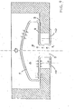
- FIG. 1 shows in cross section the wall of an annular recess machined out of an airtight container (not shown).
- a central through opening 7 is provided at the bottom of the annular recess.
- Fig. 1 further shows a vent valve not yet attached to the airtight container, which is essentially mushroom-shaped in cross-section and has a hollow valve body 2, a hollow straight shaft 11 and at its lower end an annular clamping plate provided with outlets 10.
- Fig. 2 shows the vent valve used in the recess of the airtight container.
- the annular sealing membrane 4 provided on the underside of the valve body 2 sits on the bottom of the recess and seals the container in an airtight manner in connection with a sealing seat 3.
- the vent valve is held by the clamping plate 12, which with its outer edge 6 comprises the recess on the inside. If there is no excess pressure in the container due to the gas forming, the upper side 9 of the valve body 2 has a slightly concave curvature.
- the edge region 5 of the through opening 7 is bordered on the outside by the membrane and on the inside by the edge 6 of the clamping plate 12. This ensures both the secure fit of the vent valve on the container and the airtightness of the container.
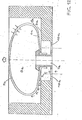
- Fig. 3 it is shown how the top 9 of the valve body 2 has swelled from its concave curvature in a straight plane.
- a gas develops in the container which, since it cannot escape from the container, accumulates in the pre-storage chamber 8 formed by the valve body 2. Since this creates an overpressure in the container, the valve body 2 swells, whereby the upper side 9 is raised.
- Fig. 5 it can be seen that the pre-storage chamber 8 of the valve body 2 is filled with gas particles 3, so that the top 9 of the valve body has deformed further outwards. Now the edge of the top 9 pulls the outer edge 13 of the membrane 4 upward, so that the membrane 4 stands out from the sealing seat 3. Because of the excess pressure acting in the container, gas particles flow out of the container through the outlets 10, which is represented by arrows 14.
- valve body 2 has shrunk again, since some of the gas particles previously located in the pre-storage chamber 8 have escaped through the outlets 10. As a result, the excess pressure in the valve body 2 was reduced. The upper side 9 of the valve body has lowered again and at the same time the sealing membrane 4 has again placed on the sealing seat 3. The valve therefore closed and the airtightness of the container was restored before a complete pressure equalization between inside and outside pressure could occur. In the event of renewed gas accumulation within the container, the pre-storage chamber 8 would fill up again with gas particles, the excess pressure would cause the valve body 2 to swell until the membrane lifts off from its sealing seat and gas could escape through the passages 10.
- Fig. 7 shows a vent valve on a container under vacuum.
- the upper side of the valve body has placed on the membrane 4 under the prevailing greater external pressure and this is pressed onto the sealing seat 3, sealing the container airtight.
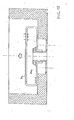
- FIG. 8 shows an annular recess 1a on an airtight container, in the central area of which a central pin provided with an undercut is provided.
- the central pin is provided with a central through hole 7a and in addition to the central pin, passages 10a are formed in the bottom of the recess.
- a vent valve not yet attached to the container has a valve body 2a and a cylindrical center shaft 11a.
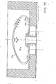
- Fig. 9 shows the vent valve which is mounted in the recess of the container.
- the outer edge area of the annular sealing membrane 4a formed on the underside of the valve body 2a is seated on a sealing seat 3a in the recess.
- the inner edge of the membrane 4a engages under the undercut, which is provided on the upper edge of the central shaft of the recess.
- the wall 11a of the stem of the vent valve lies against the outer wall of the central stem 5a of the recess.
- F ig. 14 shows a vent valve on a container under negative pressure.
- the upper side 9a of the sealing body lies on the membrane 4a, which rests firmly on the sealing seat 3a and closes the container airtight to the outside.
- vent valve according to the invention for airtight containers can be used both on containers that are under atmospheric pressure or on containers that are under vacuum.
- the invention includes all vent valves which have an elastic valve body in the form of a hollow capsule or dome, which form a pre-storage chamber.
Landscapes
- Engineering & Computer Science (AREA)
- Mechanical Engineering (AREA)
- Self-Closing Valves And Venting Or Aerating Valves (AREA)
- Packages (AREA)
- Closures For Containers (AREA)
Applications Claiming Priority (2)
| Application Number | Priority Date | Filing Date | Title |
|---|---|---|---|
| IT03442/80A IT1194936B (it) | 1980-06-03 | 1980-06-03 | Valvola di sfiato per contenitori ermetici |
| IT344280 | 1980-06-03 |
Publications (1)
| Publication Number | Publication Date |
|---|---|
| EP0041268A1 true EP0041268A1 (fr) | 1981-12-09 |
Family
ID=11107448
Family Applications (1)
| Application Number | Title | Priority Date | Filing Date |
|---|---|---|---|
| EP81104217A Withdrawn EP0041268A1 (fr) | 1980-06-03 | 1981-06-02 | Soupape de dégazage pour récipients fermés hermétiquement |
Country Status (4)
| Country | Link |
|---|---|
| EP (1) | EP0041268A1 (fr) |
| JP (1) | JPS578666A (fr) |
| ES (1) | ES8306237A1 (fr) |
| IT (1) | IT1194936B (fr) |
Cited By (2)
| Publication number | Priority date | Publication date | Assignee | Title |
|---|---|---|---|---|
| EP1097883A3 (fr) * | 1999-11-02 | 2004-06-30 | Office Ozawa co., Ltd. | Un sac d'accomodation |
| US20090277453A1 (en) * | 2005-07-19 | 2009-11-12 | Map Medizin-Technologie Gmbh | Forehead-Contacting Device for a Breathing Mask and Method for Making the Same |
Citations (6)
| Publication number | Priority date | Publication date | Assignee | Title |
|---|---|---|---|---|
| DE346651C (de) * | 1920-10-14 | 1922-01-05 | Ernst Stengele | Selbsttaetig regelnde Verschlussvorrichtung fuer Frischhaltungsgefaesse |
| FR644766A (fr) * | 1927-08-31 | 1928-10-13 | Système de fermeture ou de bouchage pour récipients destinés à contenir de grandes quantités de liquides et plus particulièrement des vins | |
| FR2000577A1 (fr) * | 1968-01-23 | 1969-09-12 | Goglio Spa Luigi Milano | |
| DE2824175A1 (de) * | 1978-06-02 | 1979-12-06 | Draegerwerk Ag | Anzeigevorrichtung fuer die dichtigkeit der verpackung fuer unter vakuum aufzubewahrende gegenstaende, insbesondere atemschutzgeraete |
| GB2031847A (en) * | 1978-10-17 | 1980-04-30 | Ica Spa | Container venting means |
| EP0011544A1 (fr) * | 1978-11-09 | 1980-05-28 | Derigon Industries, société anonyme | Valve de sécurité pour emballage |
-
1980
- 1980-06-03 IT IT03442/80A patent/IT1194936B/it active
-
1981
- 1981-02-20 ES ES499665A patent/ES8306237A1/es not_active Expired
- 1981-06-02 EP EP81104217A patent/EP0041268A1/fr not_active Withdrawn
- 1981-06-03 JP JP8553881A patent/JPS578666A/ja active Pending
Patent Citations (6)
| Publication number | Priority date | Publication date | Assignee | Title |
|---|---|---|---|---|
| DE346651C (de) * | 1920-10-14 | 1922-01-05 | Ernst Stengele | Selbsttaetig regelnde Verschlussvorrichtung fuer Frischhaltungsgefaesse |
| FR644766A (fr) * | 1927-08-31 | 1928-10-13 | Système de fermeture ou de bouchage pour récipients destinés à contenir de grandes quantités de liquides et plus particulièrement des vins | |
| FR2000577A1 (fr) * | 1968-01-23 | 1969-09-12 | Goglio Spa Luigi Milano | |
| DE2824175A1 (de) * | 1978-06-02 | 1979-12-06 | Draegerwerk Ag | Anzeigevorrichtung fuer die dichtigkeit der verpackung fuer unter vakuum aufzubewahrende gegenstaende, insbesondere atemschutzgeraete |
| GB2031847A (en) * | 1978-10-17 | 1980-04-30 | Ica Spa | Container venting means |
| EP0011544A1 (fr) * | 1978-11-09 | 1980-05-28 | Derigon Industries, société anonyme | Valve de sécurité pour emballage |
Cited By (4)
| Publication number | Priority date | Publication date | Assignee | Title |
|---|---|---|---|---|
| EP1097883A3 (fr) * | 1999-11-02 | 2004-06-30 | Office Ozawa co., Ltd. | Un sac d'accomodation |
| US20090277453A1 (en) * | 2005-07-19 | 2009-11-12 | Map Medizin-Technologie Gmbh | Forehead-Contacting Device for a Breathing Mask and Method for Making the Same |
| US8439040B2 (en) * | 2005-07-19 | 2013-05-14 | Resmed R&D Germany Gmbh | Forehead-contacting device for a breathing mask and method for making the same |
| US9242063B2 (en) | 2005-07-19 | 2016-01-26 | Resmed R&D Germany Gmbh | Forehead-contacting device for a breathing mask and method for making the same |
Also Published As
| Publication number | Publication date |
|---|---|
| ES499665A0 (es) | 1982-09-01 |
| IT1194936B (it) | 1988-09-28 |
| IT8003442A0 (it) | 1980-06-03 |
| ES8306237A1 (es) | 1982-09-01 |
| JPS578666A (en) | 1982-01-16 |
Similar Documents
| Publication | Publication Date | Title |
|---|---|---|
| EP0190169B1 (fr) | Recipient muni d'un obturateur | |
| EP0069264B1 (fr) | Valve de surpression notamment pour récipients d'emballage flexibles | |
| DE69811978T2 (de) | Verschlussstopfen für elektrische Speicherbatterie | |
| DE2625153A1 (de) | Wellenabdichtung | |
| DE3714388A1 (de) | Saugnapf | |
| DE1657139C3 (de) | Verschlußkappe zum hermetischen Verschließen eines Behälters | |
| EP1198700B1 (fr) | Chambre de detection de fuites sur des feuilles | |
| DE4438192C2 (de) | Druckbegrenzungsventil für ein Luftfederbein eines Kraftfahrzeuges | |
| EP1109684B1 (fr) | Dispositif d'amortissement pneumatique a fermeture automatique | |
| DD257759A5 (de) | Melkbecher fuer melkanlagen | |
| DE19907709B4 (de) | Über-/Unterdrucklüftungseinrichtung für einen Brennstofflagertank | |
| EP1036261B1 (fr) | Couvercle de fermeture | |
| DE4413322C2 (de) | Entlüftungs-Druckregelventil für ein Brennkraftmaschinen-Kurbelgehäuse | |
| WO2005047112A1 (fr) | Systeme pour faire le vide dans un recipient pour denrees alimentaires et recipient muni d'un couvercle approprie | |
| DE4121321A1 (de) | Kraftstoffbehaelter fuer ein kraftfahrzeug | |
| DE19705036B4 (de) | Überdruckventil für einen Behälter | |
| DE3830448A1 (de) | Rueckschlagventil | |
| DE2557777C3 (de) | Einrichtung zur Volumenverringerung eines betretbaren Folienbehältnisses | |
| DE2931429C2 (de) | Einrichtung zur unblutigen Blutdruckmessung | |
| DE3740159A1 (de) | Stellantrieb | |
| DE1600870C3 (de) | Ventil mit Druckmittelantrieb, einem Faltenbalg und einem Rückschlagventil an diesem | |
| DE2215574C3 (de) | VerschluBdeckel | |
| DE102006047705A1 (de) | Sicherheitseinrichtung für eine Austrittsöffnung eines Vakuumbehälters | |
| DE2822131A1 (de) | Membranrueckschlagventil | |
| DE3345599A1 (de) | Rueckschlagventil |
Legal Events
| Date | Code | Title | Description |
|---|---|---|---|
| PUAI | Public reference made under article 153(3) epc to a published international application that has entered the european phase |
Free format text: ORIGINAL CODE: 0009012 |
|
| AK | Designated contracting states |
Designated state(s): AT BE CH DE FR GB |
|
| 18D | Application deemed to be withdrawn |
Effective date: 19821113 |
|
| RIN1 | Information on inventor provided before grant (corrected) |
Inventor name: RAPPARINI, GINO |