EP0041408A2 - Lampe à décharge - Google Patents
Lampe à décharge Download PDFInfo
- Publication number
- EP0041408A2 EP0041408A2 EP81302524A EP81302524A EP0041408A2 EP 0041408 A2 EP0041408 A2 EP 0041408A2 EP 81302524 A EP81302524 A EP 81302524A EP 81302524 A EP81302524 A EP 81302524A EP 0041408 A2 EP0041408 A2 EP 0041408A2
- Authority
- EP
- European Patent Office
- Prior art keywords
- discharge lamp
- glass bead
- bead portion
- current supply
- small
- Prior art date
- Legal status (The legal status is an assumption and is not a legal conclusion. Google has not performed a legal analysis and makes no representation as to the accuracy of the status listed.)
- Granted
Links
Images
Classifications
-
- H—ELECTRICITY
- H01—ELECTRIC ELEMENTS
- H01J—ELECTRIC DISCHARGE TUBES OR DISCHARGE LAMPS
- H01J61/00—Gas-discharge or vapour-discharge lamps
- H01J61/02—Details
- H01J61/04—Electrodes; Screens; Shields
- H01J61/045—Thermic screens or reflectors
Definitions
- the present invention relates to a discharge lamp, and more particularly, but not exclusively, to a short arc type rare gas discharge lamp which operates on a relatively large current.
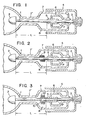
- FIG. 1 illustrates the general arrangement of an example of this type of discharge lamp.
- An electrode 2 is attached to the inner end of a current supply rod 1, the outer end of which is connected to a cylindrical metal base 4 through an intermediate lead 3.
- a sealing structure for the discharge lamp is composed of a glass bead portion 5 provided on the surface of the current supply rod 1, a graded seal glass portion 6 and a stem 7. In order to support the heavy electrode 2, a portion of the stem 7 is drawn into a small-diametered portion 7'.
- the current supply rod 1 and the electrode 2 are supported by the glass bead portion 5 and the small-diametered portion 7'.
- Figure 1 (and 2 and 3) the small-diametered portion 7' of the stem 7, and the adjacent portion of the current supply rod 1, are shown for the sake of clarity to be largely spaced apart. In practice, however they are maintained in very closely spaced relation and in loose contact with each other. In this way the current supply rod 1 may thermally expand relatively freely) whilst at the same time being supported.
- the small-diametered portion 7' is formed by drawing the stem 7 after heating it by means of a burner. In this case, a space 8 is provided.in the stem 7 between the small-diametered portion 7' and the glass bead portion 5 so as not to exert a bad thermal influence on the latter.
- the current supply rod 1 is heated by Joule heat or the like, resulting in the glass bead portion 5 being also heated.
- a discharge lamp in which a heat-radiator member is mounted on a current supply rod between a small-diametered portion of a stem and a bead portion.
- a preferred embodiment of the present invention provides a short arc type rare gas discharge lamp which is designed to effectively keep low the temperature of its glass bead portion whilst at the same time permitting the distance between the glass bead portion and the electrode to be reduced or kept short.
- Fig. 2 is explanatory of an embodiment of the present invention, the major part of which is identical with the prior art embodiment of Fig. 1,
- Reference numeral 9 indicates a tungsten wire closely wound in two layers on the current supply rod 1 between the glass bead portion 5 and the small-diametered portion 7' of the stem 7.
- FIG. 3 is explanatory of another embodiment of the present invention.
- Reference numeral 10 designates a cylindrical metal member firmly fixed on the current supply rod 1 between the glass bead portion 5 and the small-diametered portion 7'.
- the cylindrical metal member 10 has formed on the outer peripheral surface thereof disc-shaped radiation fins 10'.
- heat conveyed to the tungsten wire 9 or the radiation fins 10' is effectively radiated in the space 8.
- the temperature of the glass bead portion could be lowered about 60 o C.
- the temperature measurement point is indicated by P.
- the present invention employs lowering the temperature of the glass bead portion 5 by making positive use of the space 8 which is formed in the vicinity of the glass bead portion 5, and by mounting a radiating member 9 or 10" on the current supply rod 1 between the glass bead portion 5 and the small-diametered portion 7' of the stem 7.
- a discharge lamp in which the distance L between the electrode 2 and the glass bead portion 5 may be smaller than in a prior art discharge lamp.
- L is drawn equal in all cases merely for convenience.
- the radiating member 9 or 10' is disposed in space 8 which has not been utilized in the past, the overall length of the lamp may be reduced or kept short with practically no necessity of changing the external appearance and the shape of the lamp. Accordingly, the present invention may be of great utility in practical use.
Landscapes
- Vessels And Coating Films For Discharge Lamps (AREA)
- Discharge Lamps And Accessories Thereof (AREA)
Applications Claiming Priority (2)
| Application Number | Priority Date | Filing Date | Title |
|---|---|---|---|
| JP7927980U JPS6336607Y2 (fr) | 1980-06-09 | 1980-06-09 | |
| JP79279/80 | 1980-06-09 |
Publications (3)
| Publication Number | Publication Date |
|---|---|
| EP0041408A2 true EP0041408A2 (fr) | 1981-12-09 |
| EP0041408A3 EP0041408A3 (en) | 1981-12-16 |
| EP0041408B1 EP0041408B1 (fr) | 1985-08-28 |
Family
ID=13685420
Family Applications (1)
| Application Number | Title | Priority Date | Filing Date |
|---|---|---|---|
| EP81302524A Expired EP0041408B1 (fr) | 1980-06-09 | 1981-06-08 | Lampe à décharge |
Country Status (5)
| Country | Link |
|---|---|
| EP (1) | EP0041408B1 (fr) |
| JP (1) | JPS6336607Y2 (fr) |
| DE (1) | DE3172015D1 (fr) |
| DK (1) | DK157640C (fr) |
| ES (1) | ES258846Y (fr) |
Cited By (3)
| Publication number | Priority date | Publication date | Assignee | Title |
|---|---|---|---|---|
| GB2274350A (en) * | 1992-12-16 | 1994-07-20 | Gen Electric | Means for supporting and sealing the lead structure of a lamp |
| WO2007036518A3 (fr) * | 2005-09-28 | 2008-02-14 | Patent Treuhand Ges Fuer Elektrische Gluehlampen Mbh | Lampe a decharge |
| CN101584023B (zh) * | 2006-12-22 | 2011-12-28 | 奥斯兰姆有限公司 | 灯装置和用于制造灯装置的方法 |
Families Citing this family (1)
| Publication number | Priority date | Publication date | Assignee | Title |
|---|---|---|---|---|
| US5011577A (en) * | 1989-06-08 | 1991-04-30 | Jwi Ltd. | Pressure control forming section |
Family Cites Families (4)
| Publication number | Priority date | Publication date | Assignee | Title |
|---|---|---|---|---|
| US534443A (en) * | 1895-02-19 | Combined blacking-case and chair | ||
| US3315116A (en) * | 1965-10-22 | 1967-04-18 | Norman C Beese | High intensity short-arc lamp having bi-metallic electrode leads |
| US3970883A (en) * | 1975-04-07 | 1976-07-20 | Varian Associates | Arc lamp with movable electrode |
| NL7506655A (nl) * | 1975-06-05 | 1976-12-07 | Philips Nv | Korte-boog ontladingslamp. |
-
1980
- 1980-06-09 JP JP7927980U patent/JPS6336607Y2/ja not_active Expired
-
1981
- 1981-06-04 DK DK248481A patent/DK157640C/da not_active IP Right Cessation
- 1981-06-05 ES ES1981258846U patent/ES258846Y/es not_active Expired
- 1981-06-08 EP EP81302524A patent/EP0041408B1/fr not_active Expired
- 1981-06-08 DE DE8181302524T patent/DE3172015D1/de not_active Expired
Cited By (5)
| Publication number | Priority date | Publication date | Assignee | Title |
|---|---|---|---|---|
| GB2274350A (en) * | 1992-12-16 | 1994-07-20 | Gen Electric | Means for supporting and sealing the lead structure of a lamp |
| GB2274350B (en) * | 1992-12-16 | 1996-10-30 | Gen Electric | Discharge lamp |
| WO2007036518A3 (fr) * | 2005-09-28 | 2008-02-14 | Patent Treuhand Ges Fuer Elektrische Gluehlampen Mbh | Lampe a decharge |
| CN101273435B (zh) * | 2005-09-28 | 2010-05-19 | 电灯专利信托有限公司 | 放电灯 |
| CN101584023B (zh) * | 2006-12-22 | 2011-12-28 | 奥斯兰姆有限公司 | 灯装置和用于制造灯装置的方法 |
Also Published As
| Publication number | Publication date |
|---|---|
| DK157640B (da) | 1990-01-29 |
| DK248481A (da) | 1981-12-10 |
| EP0041408B1 (fr) | 1985-08-28 |
| JPS574160U (fr) | 1982-01-09 |
| JPS6336607Y2 (fr) | 1988-09-28 |
| ES258846U (es) | 1982-03-16 |
| ES258846Y (es) | 1982-11-01 |
| DE3172015D1 (en) | 1985-10-03 |
| DK157640C (da) | 1990-07-02 |
| EP0041408A3 (en) | 1981-12-16 |
Similar Documents
| Publication | Publication Date | Title |
|---|---|---|
| US4598194A (en) | Quartz infra-red lamps | |
| JP2002063870A (ja) | 赤外線放射装置 | |
| US3619697A (en) | Mercury vapor discharge lamp and pressure-regulating means therefor | |
| US4281267A (en) | High intensity discharge lamp with coating on arc discharge tube | |
| US2339166A (en) | Circular electric lamp | |
| US4156831A (en) | Fluorescent lamp having heater circuit disconnect device | |
| EP0041408B1 (fr) | Lampe à décharge | |
| US3286118A (en) | Electric incandescent lamps | |
| JP3562247B2 (ja) | 赤外線電球 | |
| US4857709A (en) | Electric cooking unit having an electric lamp with a helical filament contact with the lamp vessel wall | |
| JPH02181358A (ja) | 白熱電気ランプおよびその製造方法 | |
| US3275874A (en) | Electrically energized heat radiator | |
| US2188298A (en) | Seal for evacuated devices | |
| US2622222A (en) | Infrared heating and cooking lamp | |
| US4433271A (en) | High pressure discharge lamp | |
| JPS5866253A (ja) | 高輝度放電ランプ | |
| JP2004502278A (ja) | 押圧封止部内で緊締されたフィラメント脚部を有するハロゲン白熱ランプ | |
| US2116681A (en) | Electric lamp | |
| US2346654A (en) | Heating filament circuit | |
| JP4099702B2 (ja) | 電球形蛍光ランプおよび照明装置 | |
| US4835443A (en) | High voltage hard glass halogen capsule | |
| US2524455A (en) | Mount assembly for sun lamps | |
| EP0316986A1 (fr) | Unité de cuisson électrique et appareil de cuisson électrique muni d'une telle unité | |
| US3265922A (en) | Electric lamp | |
| EP0271857B1 (fr) | Filament incandescent bispiralé compact muni de supports |
Legal Events
| Date | Code | Title | Description |
|---|---|---|---|
| PUAI | Public reference made under article 153(3) epc to a published international application that has entered the european phase |
Free format text: ORIGINAL CODE: 0009012 |
|
| PUAL | Search report despatched |
Free format text: ORIGINAL CODE: 0009013 |
|
| AK | Designated contracting states |
Designated state(s): DE GB IT NL |
|
| AK | Designated contracting states |
Designated state(s): DE GB IT NL |
|
| 17P | Request for examination filed |
Effective date: 19820520 |
|
| RBV | Designated contracting states (corrected) |
Designated state(s): DE GB IT NL |
|
| ITF | It: translation for a ep patent filed | ||
| GRAA | (expected) grant |
Free format text: ORIGINAL CODE: 0009210 |
|
| AK | Designated contracting states |
Designated state(s): DE GB IT NL |
|
| REF | Corresponds to: |
Ref document number: 3172015 Country of ref document: DE Date of ref document: 19851003 |
|
| PLBE | No opposition filed within time limit |
Free format text: ORIGINAL CODE: 0009261 |
|
| STAA | Information on the status of an ep patent application or granted ep patent |
Free format text: STATUS: NO OPPOSITION FILED WITHIN TIME LIMIT |
|
| 26N | No opposition filed | ||
| ITTA | It: last paid annual fee | ||
| PGFP | Annual fee paid to national office [announced via postgrant information from national office to epo] |
Ref country code: DE Payment date: 19920616 Year of fee payment: 12 |
|
| PGFP | Annual fee paid to national office [announced via postgrant information from national office to epo] |
Ref country code: NL Payment date: 19920630 Year of fee payment: 12 |
|
| PGFP | Annual fee paid to national office [announced via postgrant information from national office to epo] |
Ref country code: GB Payment date: 19930309 Year of fee payment: 13 |
|
| PG25 | Lapsed in a contracting state [announced via postgrant information from national office to epo] |
Ref country code: NL Effective date: 19940101 |
|
| NLV4 | Nl: lapsed or anulled due to non-payment of the annual fee | ||
| PG25 | Lapsed in a contracting state [announced via postgrant information from national office to epo] |
Ref country code: DE Effective date: 19940301 |
|
| PG25 | Lapsed in a contracting state [announced via postgrant information from national office to epo] |
Ref country code: GB Effective date: 19940608 |
|
| GBPC | Gb: european patent ceased through non-payment of renewal fee |
Effective date: 19940608 |