EP0041437B1 - Verfahren und Anordnung zur Differenzierung eines elektrischen analogen Signals - Google Patents
Verfahren und Anordnung zur Differenzierung eines elektrischen analogen Signals Download PDFInfo
- Publication number
- EP0041437B1 EP0041437B1 EP81400824A EP81400824A EP0041437B1 EP 0041437 B1 EP0041437 B1 EP 0041437B1 EP 81400824 A EP81400824 A EP 81400824A EP 81400824 A EP81400824 A EP 81400824A EP 0041437 B1 EP0041437 B1 EP 0041437B1
- Authority
- EP
- European Patent Office
- Prior art keywords
- analog
- digital
- value
- signal
- difference
- Prior art date
- Legal status (The legal status is an assumption and is not a legal conclusion. Google has not performed a legal analysis and makes no representation as to the accuracy of the status listed.)
- Expired
Links
Images
Classifications
-
- G—PHYSICS
- G01—MEASURING; TESTING
- G01P—MEASURING LINEAR OR ANGULAR SPEED, ACCELERATION, DECELERATION, OR SHOCK; INDICATING PRESENCE, ABSENCE, OR DIRECTION, OF MOVEMENT
- G01P3/00—Measuring linear or angular speed; Measuring differences of linear or angular speeds
- G01P3/62—Devices characterised by the determination or the variation of atmospheric pressure with height to measure the vertical components of speed
-
- G—PHYSICS
- G06—COMPUTING OR CALCULATING; COUNTING
- G06J—HYBRID COMPUTING ARRANGEMENTS
- G06J1/00—Hybrid computing arrangements
Definitions
- the present invention relates to a method and a device for obtaining the derivative of an analog electrical signal varying slowly as a function of a parameter.
- the invention applies very particularly, although not exclusively, to the very precise calculation of the vertical speeds of aircraft cabins, with a view to regulating them in pressure variation, or after correction, in upward or downward speed.
- the device according to the invention is therefore particularly suitable for processing signals from barometric pressure sensors, that is to say from analog electrical signal pressure transducers.
- the former do not provide usable information for slow pressure variations and are mainly used as flight indicators, especially in simple design aircraft.
- the latter use analog electrical pressure transducers and said signal is derived using an R.C. circuit and an amplifier to provide a vertical speed signal.
- the accuracy of the signal supplied is insufficient to indicate slow variations intended to be used for the internal pressure regulation of a pressurized aircraft cabin.
- the present invention overcomes these drawbacks thanks to a combination of digital and analog technology making it possible to obtain a very high resolution.
- the corresponding electronic device comprises means for sampling and analog-digital conversion of the input signal Y (t), means for taking into memory several successive values of Y (t) under binary form, means for calculating ⁇ Y and means for digital-analog conversion providing an output voltage proportional to the value of the derivative.
- the present invention implements a different method and device.
- the report is thus obtained in digital form.
- the formation of said first and second analog differences is accompanied by a high gain amplification.
- analog value P 12 is obtained by conver digital-analog value of the most significant bits of said first digital code representative of the analog value P l .
- the invention can be implemented for obtaining the derivative of any analog electrical signal P, a function of any variable t.
- the analog electrical signal P it is advantageous for the analog electrical signal P to be representative of the pressure outside or inside an aircraft as a function of the altitude of the latter, this altitude being itself a function of time t.
- a device for implementing the invention is associated with a generator of the analog electrical signal P and comprises means for analog-digital conversion of said signal P, means for storing several successive values of said signal P and means for calculating differences between different values of said signal P, and is remarkable in that it comprises a multiplexer with two inputs and a single output provided with controlled connection means between each of said inputs and said output, one of said inputs of multiplexer receiving the signal P from said generator; a comparator, the output of which is connected to the other input of said multiplexer and the input of which also receives the signal P from the generator; an analog-digital converter whose input is connected to the output of said multiplexer; a first memory intended to receive from said analog-digital converter at least the most significant bits of the first digital value representative of the analog value P l ; a digital-analog converter which is in permanent connection with said first memory and whose output is combined with the other input of said comparator; a second memory intended to receive from said analog-digital converter said second digital value representative of said
- Said comparator is advantageously formed by a high gain differential amplifier, determined by the value of two resistors, one of which is mounted between the input, connected to the digital analog converter, and the output of said differential amplifier, while the other of said resistors is mounted in the link between said digital-analog converter and said differential amplifier.
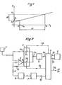
- the device according to the invention comprises a sensor-transducer 1, capable of delivering an analog electrical signal P, representative of a pressure, for example an atmospheric pressure varying according to the altitude from 0 to 3000 m.
- the signal P varies for example from 10 millivolts per millibar and, for example, the pressure varies from one millibar per second.
- the device of FIG. 2 is for example mounted on board an aircraft.
- the signal P supplied by the sensor 1 has the value P 1
- the signal P takes a different value P 2 .
- the output of the sensor 1 is connected in parallel, on the one hand, to a first input 2a of a multiplexer circuit 2 and, on the other hand, to the positive input of a differential amplifier 3, the gain of which is by example equal to 256, i.e. 2 8 .
- the multiplexer 2 is shown diagrammatically as comprising two switches 2c and 2d in parallel with each other and respectively in series between two inputs 2a and 2b of the multiplexer 2 and the single output 2e of the latter.
- the output of the differential amplifier 3 is connected to the input 2b of the multiplexer 2, while the output 2e of the latter is connected to an analog-digital converter 4, for example 12 bits, whose output is connected by a link 5a to a microprocessor 5, by links 5b and 5c, the microprocessor 5 is able to control the switches 2c and 2d.
- the microprocessor 5 is linked to a memory 6.
- memory 7 is connected to the microprocessor 5 by a link 5f.
- the output of memory 7 is connected to a digital-analog converter, for example to 8 bits, whose output is connected to the negative input of the differential amplifier 3 by a resistor 9.
- a resistor 10 is mounted between the output and the negative input of the differential amplifier 3.
- the resistors 9 and 10 make it possible to determine the gain of the differential amplifier 3.
- the operating process of the device according to the invention comprises three successive and respectively repetitive sequences, controlled by the clock and counting means of the microprocessor 5.
- the first operating sequence occurs at time t 1 , and, at this time, the microprocessor closes the switch 2c and opens the switch 2d (thanks to the links 5b and 5c), so that the value P 1 is transferred directly to the converter 4, which digitizes it with a resolution of 12 bits and transmits to the microprocessor 5 the corresponding digital value.
- This microprocessor selects the eight most significant bits of this 12-bit digital value representative of the value P 1 and transfers them, via the link 5f, into memory 7, where they remain stored until the end of the process.
- the digital-analog converter 8 transforms these eight bits into an analog value P 12 , applied to the negative input of the differential amplifier 3, by means of the resistor 9. Thanks to memory 7, the analog value P 12 remains permanently until the end of the process, on the output of converter 8.
- ⁇ P represents the error introduced by the device on the value P and due to the double conversion (by the converters 4 and 8) and by the intermediate storage (in memory 7).
- the microprocessor 5 opens the switch 2c and closes the switch 2d, so that the difference signal 8P is transmitted to the converter 4 which digitizes it, after which said microprocessor 5 enters memory 6 (via link 5d) the 12-bit value representative of ⁇ P. Then, the microprocessor 5 opens the switch 2d, the switch 2c also remaining open.
- the switches 2d and 2c are thus kept open for a time space ⁇ t, for example equal to 1 second, leading to the instant t 2 .
- the microprocessor 5 At the end of the time space ⁇ t, that is to say at time t 2 , begins the third sequence, the microprocessor 5 then closing the switch 2d.
- the positive input of the differential amplifier 3 receives, from sensor 1, the value P 2 , while the negative input of said amplifier always receives the value P 12 of converter 8.
- the output of the differential amplifier 3 therefore appears the difference P 2 -P 12 , which is digitized by the converter 4, then transmitted to the microprocessor 5.
- the microprocessor can provide the report that is to say the speed of variation of the pressure P as a function of time t.
- ⁇ P the maximum pressure variation being of the order of 1 millibar per second
- ⁇ P will always be less than the 256 th part of P, taking into account the fact that ⁇ t is of the order of 1 second.
Landscapes
- Physics & Mathematics (AREA)
- Engineering & Computer Science (AREA)
- General Physics & Mathematics (AREA)
- Theoretical Computer Science (AREA)
- Computer Hardware Design (AREA)
- Mathematical Physics (AREA)
- Automation & Control Theory (AREA)
- Evolutionary Computation (AREA)
- Fuzzy Systems (AREA)
- Software Systems (AREA)
- Analogue/Digital Conversion (AREA)
Claims (9)

Applications Claiming Priority (2)
| Application Number | Priority Date | Filing Date | Title |
|---|---|---|---|
| FR8012381 | 1980-06-04 | ||
| FR8012381A FR2484110A1 (fr) | 1980-06-04 | 1980-06-04 | Procede et dispositif pour la derivation d'un signal electrique analogique |
Publications (2)
| Publication Number | Publication Date |
|---|---|
| EP0041437A1 EP0041437A1 (de) | 1981-12-09 |
| EP0041437B1 true EP0041437B1 (de) | 1984-02-22 |
Family
ID=9242686
Family Applications (1)
| Application Number | Title | Priority Date | Filing Date |
|---|---|---|---|
| EP81400824A Expired EP0041437B1 (de) | 1980-06-04 | 1981-05-22 | Verfahren und Anordnung zur Differenzierung eines elektrischen analogen Signals |
Country Status (6)
| Country | Link |
|---|---|
| US (1) | US4409667A (de) |
| EP (1) | EP0041437B1 (de) |
| BR (1) | BR8103572A (de) |
| CA (1) | CA1165886A (de) |
| DE (1) | DE3162354D1 (de) |
| FR (1) | FR2484110A1 (de) |
Families Citing this family (1)
| Publication number | Priority date | Publication date | Assignee | Title |
|---|---|---|---|---|
| CH685265A5 (de) * | 1992-07-09 | 1995-05-15 | Arnold Heinrich Quinke | Akzelerometer. |
Family Cites Families (4)
| Publication number | Priority date | Publication date | Assignee | Title |
|---|---|---|---|---|
| US3590229A (en) * | 1968-03-28 | 1971-06-29 | Electronics Lab Inc | Digital differentiator |
| DE2401936A1 (de) * | 1973-01-17 | 1974-07-18 | Auray Didier | Vorrichtung zum berechnen der aufeinanderfolgenden ableitungen einer funktion einer variablen, insbesondere fuer die regelung oder steuerung der funktion |
| US3978414A (en) * | 1975-03-25 | 1976-08-31 | American Optical Corporation | Apparatus and method for taking the derivative of a slowly varying electrical signal |
| US4071901A (en) * | 1976-11-08 | 1978-01-31 | Rockwell International Corporation | Analog-to-digital conversion means and associated lag compensated apparatus |
-
1980
- 1980-06-04 FR FR8012381A patent/FR2484110A1/fr active Granted
-
1981
- 1981-05-21 US US06/265,812 patent/US4409667A/en not_active Expired - Fee Related
- 1981-05-22 EP EP81400824A patent/EP0041437B1/de not_active Expired
- 1981-05-22 DE DE8181400824T patent/DE3162354D1/de not_active Expired
- 1981-05-26 CA CA000378372A patent/CA1165886A/fr not_active Expired
- 1981-06-03 BR BR8103572A patent/BR8103572A/pt unknown
Also Published As
| Publication number | Publication date |
|---|---|
| DE3162354D1 (en) | 1984-03-29 |
| EP0041437A1 (de) | 1981-12-09 |
| FR2484110A1 (fr) | 1981-12-11 |
| FR2484110B1 (de) | 1983-08-26 |
| BR8103572A (pt) | 1982-03-02 |
| US4409667A (en) | 1983-10-11 |
| CA1165886A (fr) | 1984-04-17 |
Similar Documents
| Publication | Publication Date | Title |
|---|---|---|
| EP0187081B1 (de) | Verfahren und Verarbeitungskette des analogischen Ausgangssignals eines Sensors | |
| CA2619564C (fr) | Procede pour numeriser une grandeur analogique, dispositif de numerisation mettant en oeuvre ce procede et detecteur de rayonnements electromagnetiques integrant un tel dispositif | |
| EP0293310B1 (de) | Verfahren zum Kalibrieren eines elektronischen Drehmomentschlüssels | |
| WO1989005738A1 (fr) | Codage de la valeur de plusieurs grandeurs mesurees dans un pneumatique | |
| EP0018858A1 (de) | Verfahren und Vorrichtung zur Berechnung und Regelung der Optimalisierung der Frühverstellung des Zündzeitpunktes | |
| FR2485856A1 (fr) | Systeme d'acquisition de donnees et convertisseur analogique-numerique | |
| EP2959300B1 (de) | Sensor mit einem elektrostatischen pendelartigen beschleunigungsmesser und verfahren zur steuerung solch eines sensors | |
| FR2580070A1 (de) | ||
| EP0019540B1 (de) | Vorrichtung zum Messen einer Flüssigkeitshöhe | |
| FR2787880A1 (fr) | Dispositif et procede de mesure ultrasonore de debit de fluide comportant un convertisseur analogique numerique sigma-delta passe bande | |
| EP0041437B1 (de) | Verfahren und Anordnung zur Differenzierung eines elektrischen analogen Signals | |
| FR2600159A1 (fr) | Dispositif de mesure de forces, notamment pour systeme de pesee | |
| EP0540407A2 (de) | Vorrichtung zum Messen von Parametern, insbesondere Parametern mit Bezug auf Flugzeug- oder Fahrzeugräder | |
| FR2496361A1 (fr) | Convertisseur numerique/analogique. | |
| FR2465210A1 (fr) | Systeme de determination du volume d'un espace ferme | |
| EP0053786B1 (de) | Widerstandsmesskreis | |
| FR2510330A1 (fr) | Procede et dispositif pour l'echantillonnage d'un signal sinusoidal de frequence determinee par un signal de frequence multiple de cette frequence determinee | |
| FR2605731A1 (fr) | Procede de mesure du niveau d'un liquide dans un reservoir et dispositif pour sa mise en oeuvre | |
| EP0404642B1 (de) | Vorrichtung zur Fernübertragung einer Drehbewegung | |
| JP2703469B2 (ja) | ディジタル式放射線計測装置 | |
| FR2536854A1 (fr) | Dispositif de mesure de la temperature | |
| EP0580461B1 (de) | Anordnung zur Umwandlung einer elektrischen Grösse in einer Frequenz mit der Möglichkeit zur Autokalibrierung dieser Umwandlung | |
| EP4567437B1 (de) | Messung der phase einer komplexen impedanz durch schwellenwert | |
| EP0352587A2 (de) | Elektronisches Wägegerät | |
| FR2637985A1 (fr) | Procede et appareil de mesure d'impedances resistives, notamment pour la mesure des temperatures |
Legal Events
| Date | Code | Title | Description |
|---|---|---|---|
| PUAI | Public reference made under article 153(3) epc to a published international application that has entered the european phase |
Free format text: ORIGINAL CODE: 0009012 |
|
| AK | Designated contracting states |
Designated state(s): BE CH DE GB IT NL SE |
|
| 17P | Request for examination filed |
Effective date: 19811021 |
|
| ITF | It: translation for a ep patent filed | ||
| GRAA | (expected) grant |
Free format text: ORIGINAL CODE: 0009210 |
|
| AK | Designated contracting states |
Designated state(s): BE CH DE GB IT LI NL SE |
|
| REF | Corresponds to: |
Ref document number: 3162354 Country of ref document: DE Date of ref document: 19840329 |
|
| PLBE | No opposition filed within time limit |
Free format text: ORIGINAL CODE: 0009261 |
|
| STAA | Information on the status of an ep patent application or granted ep patent |
Free format text: STATUS: NO OPPOSITION FILED WITHIN TIME LIMIT |
|
| 26N | No opposition filed | ||
| NLT1 | Nl: modifications of names registered in virtue of documents presented to the patent office pursuant to art. 16 a, paragraph 1 |
Owner name: AEROSPATIALE SOCIETE NATIONALE INDUSTRIELLE TE PAR |
|
| PGFP | Annual fee paid to national office [announced via postgrant information from national office to epo] |
Ref country code: CH Payment date: 19900426 Year of fee payment: 10 |
|
| PGFP | Annual fee paid to national office [announced via postgrant information from national office to epo] |
Ref country code: SE Payment date: 19900430 Year of fee payment: 10 |
|
| PGFP | Annual fee paid to national office [announced via postgrant information from national office to epo] |
Ref country code: GB Payment date: 19900501 Year of fee payment: 10 |
|
| PGFP | Annual fee paid to national office [announced via postgrant information from national office to epo] |
Ref country code: DE Payment date: 19900521 Year of fee payment: 10 |
|
| ITTA | It: last paid annual fee | ||
| PGFP | Annual fee paid to national office [announced via postgrant information from national office to epo] |
Ref country code: NL Payment date: 19900531 Year of fee payment: 10 |
|
| PGFP | Annual fee paid to national office [announced via postgrant information from national office to epo] |
Ref country code: BE Payment date: 19900712 Year of fee payment: 10 |
|
| PG25 | Lapsed in a contracting state [announced via postgrant information from national office to epo] |
Ref country code: GB Effective date: 19910522 |
|
| PG25 | Lapsed in a contracting state [announced via postgrant information from national office to epo] |
Ref country code: SE Effective date: 19910523 |
|
| PG25 | Lapsed in a contracting state [announced via postgrant information from national office to epo] |
Ref country code: LI Effective date: 19910531 Ref country code: CH Effective date: 19910531 Ref country code: BE Effective date: 19910531 |
|
| BERE | Be: lapsed |
Owner name: SOC. NATIONALE INDUSTRIELLE AEROSPATIALE Effective date: 19910531 |
|
| PG25 | Lapsed in a contracting state [announced via postgrant information from national office to epo] |
Ref country code: NL Effective date: 19911201 |
|
| NLV4 | Nl: lapsed or anulled due to non-payment of the annual fee | ||
| GBPC | Gb: european patent ceased through non-payment of renewal fee | ||
| REG | Reference to a national code |
Ref country code: CH Ref legal event code: PL |
|
| PG25 | Lapsed in a contracting state [announced via postgrant information from national office to epo] |
Ref country code: DE Effective date: 19920303 |
|
| EUG | Se: european patent has lapsed |
Ref document number: 81400824.9 Effective date: 19911209 |