EP0041468A2 - Zum Herstellen kolloidaler Gemische geeignete Einrichtung - Google Patents
Zum Herstellen kolloidaler Gemische geeignete Einrichtung Download PDFInfo
- Publication number
- EP0041468A2 EP0041468A2 EP81630040A EP81630040A EP0041468A2 EP 0041468 A2 EP0041468 A2 EP 0041468A2 EP 81630040 A EP81630040 A EP 81630040A EP 81630040 A EP81630040 A EP 81630040A EP 0041468 A2 EP0041468 A2 EP 0041468A2
- Authority
- EP
- European Patent Office
- Prior art keywords
- stirrer
- mixing container
- agitator
- power consumption
- water
- Prior art date
- Legal status (The legal status is an assumption and is not a legal conclusion. Google has not performed a legal analysis and makes no representation as to the accuracy of the status listed.)
- Granted
Links
Images
Classifications
-
- B—PERFORMING OPERATIONS; TRANSPORTING
- B01—PHYSICAL OR CHEMICAL PROCESSES OR APPARATUS IN GENERAL
- B01F—MIXING, e.g. DISSOLVING, EMULSIFYING OR DISPERSING
- B01F23/00—Mixing according to the phases to be mixed, e.g. dispersing or emulsifying
- B01F23/50—Mixing liquids with solids
- B01F23/53—Mixing liquids with solids using driven stirrers
-
- B—PERFORMING OPERATIONS; TRANSPORTING
- B01—PHYSICAL OR CHEMICAL PROCESSES OR APPARATUS IN GENERAL
- B01F—MIXING, e.g. DISSOLVING, EMULSIFYING OR DISPERSING
- B01F27/00—Mixers with rotary stirring devices in fixed receptacles; Kneaders
- B01F27/80—Mixers with rotary stirring devices in fixed receptacles; Kneaders with stirrers rotating about a substantially vertical axis
- B01F27/805—Mixers with rotary stirring devices in fixed receptacles; Kneaders with stirrers rotating about a substantially vertical axis wherein the stirrers or the receptacles are moved in order to bring them into operative position; Means for fixing the receptacle
-
- B—PERFORMING OPERATIONS; TRANSPORTING
- B01—PHYSICAL OR CHEMICAL PROCESSES OR APPARATUS IN GENERAL
- B01F—MIXING, e.g. DISSOLVING, EMULSIFYING OR DISPERSING
- B01F27/00—Mixers with rotary stirring devices in fixed receptacles; Kneaders
- B01F27/80—Mixers with rotary stirring devices in fixed receptacles; Kneaders with stirrers rotating about a substantially vertical axis
- B01F27/90—Mixers with rotary stirring devices in fixed receptacles; Kneaders with stirrers rotating about a substantially vertical axis with paddles or arms
-
- B—PERFORMING OPERATIONS; TRANSPORTING
- B01—PHYSICAL OR CHEMICAL PROCESSES OR APPARATUS IN GENERAL
- B01F—MIXING, e.g. DISSOLVING, EMULSIFYING OR DISPERSING
- B01F35/00—Accessories for mixers; Auxiliary operations or auxiliary devices; Parts or details of general application
- B01F35/20—Measuring; Control or regulation
- B01F35/21—Measuring
- B01F35/212—Measuring of the driving system data, e.g. torque, speed or power data
-
- B—PERFORMING OPERATIONS; TRANSPORTING
- B01—PHYSICAL OR CHEMICAL PROCESSES OR APPARATUS IN GENERAL
- B01F—MIXING, e.g. DISSOLVING, EMULSIFYING OR DISPERSING
- B01F35/00—Accessories for mixers; Auxiliary operations or auxiliary devices; Parts or details of general application
- B01F35/45—Closures or doors specially adapted for mixing receptacles; Operating mechanisms therefor
- B01F35/451—Closures or doors specially adapted for mixing receptacles; Operating mechanisms therefor by rotating them about an axis parallel to the plane of the opening
-
- B—PERFORMING OPERATIONS; TRANSPORTING
- B01—PHYSICAL OR CHEMICAL PROCESSES OR APPARATUS IN GENERAL
- B01F—MIXING, e.g. DISSOLVING, EMULSIFYING OR DISPERSING
- B01F2101/00—Mixing characterised by the nature of the mixed materials or by the application field
- B01F2101/28—Mixing cement, mortar, clay, plaster or concrete ingredients
-
- B—PERFORMING OPERATIONS; TRANSPORTING
- B01—PHYSICAL OR CHEMICAL PROCESSES OR APPARATUS IN GENERAL
- B01F—MIXING, e.g. DISSOLVING, EMULSIFYING OR DISPERSING
- B01F27/00—Mixers with rotary stirring devices in fixed receptacles; Kneaders
- B01F27/05—Stirrers
- B01F27/11—Stirrers characterised by the configuration of the stirrers
- B01F27/112—Stirrers characterised by the configuration of the stirrers with arms, paddles, vanes or blades
- B01F27/1125—Stirrers characterised by the configuration of the stirrers with arms, paddles, vanes or blades with vanes or blades extending parallel or oblique to the stirrer axis
Definitions
- the present invention relates to a device for producing colloidal mixtures, in particular pourable or sprayable colloidal water-cement mixtures, which may contain additives, and a method for operating them.
- colloidal water-cement mixtures for the production of colloidal concrete, be it on a pure water-cement basis or in the presence of aggregates, requires specific mixing plants.
- such mixtures are made by generally introducing energy into the intimately mixed components of the mixture.
- the individual cement particles are largely wetted and the mixture can be converted into a colloidal state, i.e. a state in which neither liquid water nor solid cement particles are present as such, but an intimately mixed one. homogeneous mixture that exists in a single phase.
- the applicant also described a process in her LU 81.524, the characteristics of which consist in the fact that in a mixer a proportion of 25-60% water based on the amount of cement is set in a rotary motion by means of a stirrer in such a way that the peripheral speed on the outside diameter of the Stirrer mi, n 1500 m / minute is that the mixer is filled with cement, that the rotational movement of the stirrer is maintained or throttled to at most half the circumferential speed and the mixture contains up to 2 parts of sand per amount of cement. with a degree of moisture of 5-15% so that the sand reaches the center of the funnel-shaped profile of the mixture formed by the stirring.
- Colloidal water-cement mixtures produced in this way, with or without additions, are used in particular for coating shaped parts made of steel, such as conduit pipes, boilers, containers and the like. They can also be used to inexpensively replace the expensive paints, paints, varnishes or plastic coatings used to protect against corrosion, for example on the basis of organic polymers.
- One of the main advantages of these mixtures is that the steel molded parts to be coated do not have any surface treatment, e.g. by sandblasting, which is a high factor in the calculation of the cost of conventional corrosion protection.
- the mix can rise and set on the wall of the mixer, while a cavity forms around the stirrer blades which these rotate ineffectively.
- the aim of the invention is to propose a device which allows the production of colloidal mixtures according to the knowledge obtained in the procedure and which allows contradicting conditions to be met in some cases.
- the device according to the invention which mainly understands a mixing container, a water and a solids supply device and a paddle stirrer, and which is characterized in that a drive unit, preferably arranged above the mixing container, with the stirrer fixed over egg. ne shaft is connected, which has a tightly fitting at the lower end and open at the upper end of the protective casing, the water supply pipe is aimed in the open part of the protective casing and that the mixing container can be raised and lowered so that in the highest position the ratio between, total diameter of the paddle stirrer and that of the mixing container in the middle paddle level is 1: 1.15 to 1: 2.
- the idea on which the invention is based is based on the observation that the best results with regard to the quality of the colloid mixture produced can be achieved if the material to be mixed takes the form of a standing wave in the course of the mixing and stirring process in the container, the profile of which resembles that of a lemniscate remind. Within this form, the material particles experience an acceleration that leads to extensive disintegration; the latter is responsible for the occurrence of colloidation at all.
- This acceleration of the particles can be adjusted accordingly bring about high stirring speed, but it should be noted that exceeding a certain speed limit, which depends on the respective condition of the material, the configuration of the mixing container and the design of the stirrer, in particular the blades, leads to the mixture on the container wall rises and sets, while a cavity forms in the agitator blades, in which they rotate ineffectively.
- the stirrer belonging to the device according to the invention has one or more series of blades of the same dimensions which are arranged in planes perpendicular to the stirring axis and at a distance from one another, the blades belonging to one series being at an angle to the blades of the adjacent series -measured by approximately 60 °, each wing has an inclination of approximately 12 ° to the plane in question and counter to the direction of rotation of the stirrer and the height between wings belonging to adjacent series corresponds at least to the thickness of a wing.
- a multi-level stirrer offers the advantage that the acceleration of A further acceleration, which starts from an already relatively high value, is connected downstream to a first value.
- the protective jacket surrounding the stirrer shaft.
- the container is lowered and moved horizontally, the emptied one or even one Insert and open the new container, start the stirrer and introduce the water for the next batch.
- the fact that the protective jacket is firmly attached to the stirrer shaft and therefore also rotates causes a skid effect, which contributes to keeping the shaft and the gear unit clean.
- the device according to the invention also has an advantage, which manifests itself in the procedure for the production of colloidal mixtures and in particular in relation to the question of determining the end point. For determining the point in time at which the mixture is fully colloided and after which further stirring is no longer necessary contributes to product quality and only increases the risk of setting, it is sufficient to track the power consumption of the stirrer drive.
- the stirrer is operated at a peripheral speed on the outside diameter of at least 500 and preferably 1500 m / min. It could be shown that before reaching the colloidal state, i.e. at. Presence of a solid phase in addition to a liquid phase in the mixture, the power consumption of the electric drive is irregular, the fluctuations being able to be observed on an ammeter, in particular if the latter has a running display indicator. The fluctuations come to an abrupt end at a certain point in time, which indicates that there is a colloidal single-phase system in the container. At this point and not after a certain stirring time has elapsed, it is advisable to stop stirring immediately and to process the colloided product further.
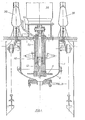
- FIG. 1 a possible embodiment of the device according to the invention
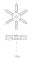
- FIG. 2 show a preferred embodiment of an agitator according to the invention.
- the container (1) which can have a hinged bottom part (2) for access to the agitator (10).
- the container (1) can be raised and lowered on suitable lifting devices (20).
- the agitator (10) shows a one-story wing design (11).
- On the shaft (12) of the agitator (10) is the protective jacket (13) open in the upper part.
- the water supply device (14) is aimed at the open upper part of the jacket (13): the electric motor (30) is equipped with a measuring device (not shown) which allows the power consumption and in particular its fluctuations to be tracked. It is easily possible to couple the measuring device to a module that visually and / or acutely indicates when the power consumption is without fluctuations and then switches off the agitator if necessary.
- a fluid coupling (not shown) is connected between the stirrer and the drive.
- Fig. 2 you can see a two-tier agitator, each with 3 blades per level.
- the wings are offset by 120 ° in each plane; the two wing series are in turn offset by 60 °.
Landscapes
- Chemical & Material Sciences (AREA)
- Chemical Kinetics & Catalysis (AREA)
- Dispersion Chemistry (AREA)
- Mixers Of The Rotary Stirring Type (AREA)
Abstract
Description
- Die vorliegende Erfindung betrifft eine Einrichtung zum Herstellen kolloidaler Gemische, insbesondere vergiess- bzw. verspritzbarer kolloidaler Wasser-Zement-Gemische, die Zuschläge enthalten können, sowie ein Verfahren zu deren Betreiben.
- Die Entwicklung kolloidaler Wasser-Zement-Gemische zum Herstellen von kolloidalem Beton, sei es auf reiner Wasser-Zement-Basis, oder in Gegenwart von Zuschlägen, erfordert spezifische Mischanlagen. In der Tat werden solche Gemische hergestellt, indem man generell in die innig miteinander vermengten Gemisch-Komponenten Energie einleitet. Unter dem Einfluss der eingeleiteten Energie werden die einzelnen Zementpartikel weitgehend benetzt und man kann das Gemisch in einen kolloidalen Zustand überführen, in einen Zustand also, in welchem weder flüssiges Wasser, noch feste Zementpartikel als solche vorliegen, sondern ein innig vermengtes,. homogenes Gemisch, das in einer einzigen Phase existi.ert.
- Das Einleiten von Energie in ein anfänglich vorliegendes ZweiPhasen-System, bestehend aus Wasser sowie darin suspendiertem festen Zement, wird selbstverständlich am besten vermittels eines geeigneten Rührers vollzogen.
- So kann man bspw. gemäss den in der DE-OS 27 18 236 beschriebenen Verfahren in einem Mischer Zement und Wasser in einem Verhältnis von 0,25-0,6 während eines Zeitraumes von etwa 2 Minuten mit einer Rührer-Umfangsgeschwindigkeit von etwa 300 m/Minute vormischen und dann mindestens 8 Minuten lang einer Massenbeschleunigung von mindestens 2 g (g = 9,81 m/sec2) aussetzen.
- Weiter hat die Anmelderin in ihrer LU 81.524 ein Verfahren beschrieben, dessen Merkmale darin bestehen, dass man in einem Mischer einen auf die Zementmenge bezogenen Anteil von 25-60 % Wasser mittels eines Rührers in eine Drehbewegung solcher Art versetzt, dass die Umfangsgeschwindigkeit am Aussendurchmesser des Rührers mi,n 1500 m/Minute beträgt, dass man den Mischer mit Zement beschickt, dass man die Drehbewegung des Rührers beibehält oder auf höchstens die Hälfte der Umfangsgeschwindigkeit drosselt und dem Gemisch einen Anteil von bis zu 2 Teilen Sand pro Zementmenge. mit einem Feuchtigkeitsgrad von 5-15 % so zuführt, dass der Sand in das Zentrum des durch das Rühren gebildeten trichterförmigen Profils des Mischgutes gelangt.
- Es wurde festgestellt, dass die Zugabe von Sand überraschenderweise bewirkt, dass weniger hochwertige Zemente, die sich wohl gut kolloidieren lassen aber des öfteren Gemische ohne ausrei.chendes Haftvermögen ergeben, unter den erfindungsgemässen Bedingungen verwendet werden können, was unbestreitbare Vorteile sowohl in Punkto Gestehungskosten als auch hinsichtlich der Versorgung an Rohstoffen mit sich bringt.
- Solcherart hergestellte kolloidale Wasser-Zement-Gemische, mit oder ohne Zuschläge, dienen insbesondere zum Beschi-chten von Formteilen aus Stahl, wie Leitungsrohren, Kesseln, Behältern u.dgl. Sie können auch dazu herangezogen werden die teuren zum Schutz gegen Korrosion verwendeten Anstriche, Farben, Lacke oder Kunststoffüberzüge bspw. auf der Basis organischer Polymerer, preisgünstig zu ersetzen. Hierbei besteht einer der Hauptvorteile dieser Gemische darin, dass die zu beschichteten Formteile aus Stahl keiner Oberflächenbehandlung, z.B. durch Sandstrahlen, bedürfen , die einen hohen Faktor bei der Berechnung der Gestehungskosten für den konventionellen Korrosionsschutz darstellt.
- Allerdings ist erwiesen, dass bereits geringfügige Abweichungen von den einzelnen Verfahrensbedingungen, wie z.B. eine zu hohe oder zu niedrige Sandfeuchtigkeit, oder eine nicht verfahrensgerechte Zuführung des Sandes zum Scheitern des Herstellungsprozesses führen.
- So kann im Fall einer nicht verfahrensgerechten Zugabe des Sandteiles das Mischgut an der Wandung des Mischers hochsteigen und abbinden, während sich um die Rührerflügel ein Hohlraum bildet in welchem diese wirkungslos rotieren.
- Weiter darf man, um ein frühzeitiges Abbinden des Mischgutes zu vermei.den, die Mischzeit nicht überschreiten; gleichzeitig ist es notwendig, das Mischen und Rühren möglichst lange und intensiv zu betreiben, da dies die unabdingbare Voraussetzung zur Kolloidierung selbst darstellt.
- Das Ziel der Erfindung besteht darin, eine Einrichtung vorzuschlagen, die die Herstellung kolloidaler Gemische gemäss den gewonnenen Erkenntni.ssen in der Verfahrensweise erlaubt und die zum Teil widersprüchlichen Bedingungen zu erfüllen gestattet.
- Dieses Ziel wird voll erreicht durch die erfindungsgemässe Einrichtung, die in der Hauptsache einen Mischbehälter, eine Wassersowie eine Feststoffzufuhr-Vorrichtung und einen Flügel-Rührer begreift und die dadurch gekennzeichnet ist, dass ein vorzugsweise über dem Mischbehälter angeordnetes Antriebaggregat mit dem Rührer feststehend über ei.ne Welle verbunden ist, die einen am unteren Ende fest anliegenden und am oberen Ende offenen Schutzmantel aufweist, wobei das Wasserzufuhrrohr in den offenen Teil des Schutzmantels zielt und dass der Mischbehälter heb- und senkbar so angeordnet ist, dass in Höchststellung das Verhältnis zwischen, Gesamtdurchmesser des Flügel-Rührers und dem des Mischbehälters in der mittleren Flügelebene 1:1,15 bis 1:2 beträgt.
- Die der Erfindung zugrundeliegende Idee stützt sich auf die Beobachtung, dass die besten Resultate hinsichtlich der Qualität des hergestellten Kolloidgemisches dann zu erzielen sind, wenn das Mischgut im Verlauf des Misch- und Rührvorganges im Behälter die Form einer stehenden Welle annimmt, deren Profil an eine Lemniskate erinnert. Innerhalb dieser Form erfahren die Materialteilchen eine Beschleunigung, die zu einer weitgehenden Desintegration führt; letztere ist dafür verantwortlich, dass es überhaupt zu einer Kolloidierüng kommt.
- Diese Beschleunigung der Teilchen kann man durch eine entsprechend hohe Rührgeschwindigkeit herbeiführen, wobei jedoch zu beachten ist, dass das Ueberschreiten einer gewissen Geschwindigkeitsgrenze, die vom jeweiligen Zustand des Materials, von der Konfiguration des Mischbehälters und von der Ausbildung des Rühreres, insbesondere der Flügel abhängt, dazu führt, dass das Mischgut an der Behälterwand hochsteigt und abbindet, während sich um die Rührerflügel ein Hohlraum bildet, in welchem diese wirkungslos rotieren.
- Geht man davon aus, dass konventionelle Rührer mit geneigten Flügeln eine bestimmte Beschleunigung der Teilchen bewirken, so ist es erfindungsgemäss sinnvoll, sich nicht durch das oben erwähnte Geschwindigkeitsmaximum eingrenzen zu lassen, sondern ein Mehr an Beschleunigung dadurch herbeizuführen, dass man mehrere Beschleuniger vorsieht, deren Einzelwirkungen kumulativ sind.
- Aus diesem Grunde weist der zu der erfindungsgemässen Vorrichtung gehörende Rührer eine bzw. mehrere in zur Rührachse- senkrechten Ebenen und mit einem Abstand zueinander angeordnete Serien von Flügeln gleicher Abmessungen auf, wobei die zu einer Serie gehörenden Flügel gegenüber den Flügeln der benachbarten Serie um ein Winkel-mass von annähernd 60° versetzt sind, jeder Flügel zur besagten Ebene und entgegen der Rührer-Drehrichtung eine Neigung von annähernd 12° aufweist und der Höhenstand zwischen zu benachbarten Serien gehörenden Flügeln zumindest dem Dickenmass eines Flügels entspricht.
- Während bei Verwendung eines einstöckigen Rührers, also eines Rührers, der eine gewisse Anzahl Flügel aufweist die alle in einer Ebene liegen, der Beschleunigungseffekt ledi.glich Funktion der Drehzahl und des Flügel-Neigungswinkels ist, bietet ein mehrstöckiger Rührer den Vorteil, dass der Beschleunigung von Null auf einen ersten Wert eine weitere Beschleunigung nachgeschaltet ist, die von einem bereits relativ hohen Wert ausgeht.
- Zum Schutz des Rührwerkes vor Verschmutzungen durch abgebundene Kolloidgemischreste, bzw. zur Erleichterung der Reinigung, dient erfindungsgemäss der die Rührerwelle umgebende Schutzmantel.
- In der Tat genügt es, wie erfindungsgemäss vorgesehen, das Wasser in den Mantel zu leiten um zu bewirken, dass das Rührwerk von Verunreinigungen befreit bzw. freigehalten wird und zwar wird man nach erfolgter Kolloidierung den Behälter absenken und horizontal verfahren, den entleerten oder auch einen neuen Behälter ein-und auffahren, den Rührer in Bewegung setzen und das Wasser für die nächste Charge einführen. Di.e Tatsache dass der Schutzmantel an de Rührerwelle fest anliegt und daher mitdreht, bewirkt einen Schleudereffekt, der zur Reinhaltung der Welle sowie des Getriebes beiträgt.
- Die erfindungsgemässe Einrichtung besitzt ferner eine Vorzug, der sich in der Verfahrensweise bei der Herstellung kolloidaler Gemische und insbesondere in Bezug auf die Frage der" Endpunktbestimmung äussert. Zur Bestimmung des Zeitpunktes, zu welchem das Gemisch voll durchkolloidiert ist und nach welchem ein weiteres Rühren nichts mehr zur Produktqualität beiträgt und nur die Gefahr eines Abbindens vergrössert, genügt es in der Tat, die Leistungsaufnahme des Rührerantriebes zu verfolgen.
- Der Rührer wird erfindungsgemäss mit einer Umfangsgeschwindigkeit am Aussendurchmesser von zumindest 500 und vorzugsweise 1500 m/min betrieben. Es konnte erwiesen werden, dass vor Erreichen des kolloidalen Zustandes, d.h. bei. Anwesenheit einer Fest- neben einer Flüssigphase im Gemisch, die Leistungsaufnahme des elektrischen Antriebs unregelmässig ist, wobei die Schwankungen an einem Amperemeter beobachtet werden können, insbesondere wenn letzterer eine laufende Schrei.beranzeige aufweist. Die Schwankungen nehmen zu einem bestimmten Zeitpunkt ein jähes Ende, was darauf hinweist, dass sich im Behälter ein kolloidales Einphasensystem befindet. Zu diesem Zeitpunkt und nicht etwa nach Ablaufen einer bestimmten Rührzeit empfielt es sich, das Rühren sofort abzustellen und das kolloidierte Produkt weiterzuverarbeiten.
- Zur bildhaften Darstellung dienen die Zeichnungen die in nicht einschränkender Weise in Fig.1 eine mögliche Ausführungsform der erfindungsgemässen Vorrichtung, und in Fig.2 eine bevorzugte Anführungsform eines erfindungsgemässen Rührwerkes zeigen.
- Man erkennt den Behälter ( 1 ), der zwecks Zugang zum Rührwerk (10) eine aufklappbare Bodenpartie ( 2 ) aufweisen kann. Der Behälter ( 1 ) ist heb- und senkbar an geeigneten Hubvorrichtungen (20) angeordnet. Das Rührwerk (10) zeigt eine einstöckige Flügelausführung (11). An der Welle (12) des Rührwerks (10) befindet sich der in der Obenpartie offene Schutzmantel (13). In die offene Obenpartie des Mantels (13) zielt die Wasserzufuhr-Vorrichtung (14): Der Elektromotor (30) ist mit einer nicht dargestellten Messvorrichtung ausgerüstet, die es erlaubt, die Leistungsaufnahme und insbesondere deren Schwankungen zu verfolgen. Es ist ohne weiteres möglich, die Messvorrichtung mit einem Modul zu kopplen, das optisch und/oder akutisch anzeigt wann die Leistungsaufnahme ohne Schwankungen verläuft und das Rührwerk dann ggf. abschaltet. Zur Verringerung des insbesondere bei mehrstöckigen, breiten Rührern auftretenden hohen Anfahrmomentes wird eine nicht gezeigte Flüssigkeitskupplung zwischen Rührwerk und Antrieb geschaltet.
- In Fig.2 erkennt man ein zweitstöckiges Rührwerk, das je 3 Flügel pro Ebene aufweist. In jeder Ebene sind die Flügel um 120° gegeneinander versetzt; die beiden Flügelserien sind wiederum um 60° gegeneinander versetzt.
- Die erfindungsgemässe Einrichtung bietet gegenüber bekannten Einrichtungen Vorteile, die sich in 2 Weisen äussern können:
- Erstens ist es möglich kolloidale Gemische herzustellen indem man die für konventionelle Vorrichtungen notwendigen und oft kritischen Rührgeschwindigkeit bequem und risikolos herabsetzen kann. Dies ergibt auch Ersparnisse, was die apparative Ausrüstung insbesondere die Nennleistung des Motors anbelangt, der das Rührwerk antreibt.
- Zweitens ist es möglich, die üblichen Rührgeschwindigkeiten ohne Bedenken weit unter die kritische Geschwindigkeit zu senken und gleichzeitig die Dauer des Kolloidierprozesses drastisch herabzusetzen. Dies trägt dazu bei, dass bei optimaler Qualität des Endproduktes jedes Risiko eines vorzei.tigen Abbindens des Materials ausgeschaltet wird.
Claims (5)
Priority Applications (1)
| Application Number | Priority Date | Filing Date | Title |
|---|---|---|---|
| AT81630040T ATE27564T1 (de) | 1980-06-04 | 1981-05-26 | Zum herstellen kolloidaler gemische geeignete einrichtung. |
Applications Claiming Priority (4)
| Application Number | Priority Date | Filing Date | Title |
|---|---|---|---|
| LU82500 | 1980-06-04 | ||
| LU82500A LU82500A1 (de) | 1980-06-04 | 1980-06-04 | Zur herstellung kolloidaler gemische geeignete einrichtung |
| LU82988A LU82988A1 (de) | 1980-12-08 | 1980-12-08 | Zum herstellen kolloidaler gemische geeignete einrichtung und verfahren zu deren betreiben |
| LU82988 | 1980-12-08 |
Publications (3)
| Publication Number | Publication Date |
|---|---|
| EP0041468A2 true EP0041468A2 (de) | 1981-12-09 |
| EP0041468A3 EP0041468A3 (en) | 1984-09-05 |
| EP0041468B1 EP0041468B1 (de) | 1987-06-03 |
Family
ID=26640266
Family Applications (1)
| Application Number | Title | Priority Date | Filing Date |
|---|---|---|---|
| EP81630040A Expired EP0041468B1 (de) | 1980-06-04 | 1981-05-26 | Zum Herstellen kolloidaler Gemische geeignete Einrichtung |
Country Status (4)
| Country | Link |
|---|---|
| US (1) | US4464055A (de) |
| EP (1) | EP0041468B1 (de) |
| CA (1) | CA1187481A (de) |
| DE (1) | DE3176225D1 (de) |
Cited By (2)
| Publication number | Priority date | Publication date | Assignee | Title |
|---|---|---|---|---|
| EP0188738A3 (de) * | 1985-01-23 | 1987-08-26 | Röben Kolloid Entwicklung GmbH & Co. KG | Verfahren zur Behandlung eines fliessfähigen, eine flüssige Phase enthaltenden Gemisches |
| EP0237042A1 (de) * | 1986-03-11 | 1987-09-16 | Klaus Burk | Mischvorrichtung und Mischwerkzeug sowie deren Verwendung |
Families Citing this family (13)
| Publication number | Priority date | Publication date | Assignee | Title |
|---|---|---|---|---|
| CH695239C1 (de) * | 2000-01-21 | 2009-11-30 | Rosenmund Vta Ag | Einrichtung zum Behandeln von Stoffen. |
| DE3306071A1 (de) * | 1983-02-22 | 1984-08-23 | Wilfried Dipl.-Ing. 4930 Detmold Hacheney | Vorrichtung zum herstellen hochwertiger feststoff-fluessigkeits-gemische |
| DE3502071A1 (de) * | 1985-01-23 | 1986-07-24 | Battenfeld Maschinenfabriken Gmbh, 5882 Meinerzhagen | Ruehrwerk |
| DE3529185A1 (de) * | 1985-01-25 | 1986-07-31 | Herfeld, Friedrich Walter, Dr., 5982 Neuenrade | Mischer |
| US5246287A (en) * | 1986-10-28 | 1993-09-21 | British Nuclear Fuels Plc | Colloidal grout mixing apparatus and method |
| GB8625715D0 (en) * | 1986-10-28 | 1986-12-03 | British Nuclear Fuels Plc | Colloidal grout mixing apparatus |
| US5664699A (en) * | 1995-04-04 | 1997-09-09 | Simpson Technologies Corporation | Core sand preparation apparatus |
| RU2186679C1 (ru) * | 2001-01-16 | 2002-08-10 | Федеральное государственное унитарное предприятие Конструкторское бюро химавтоматики | Смесительная установка |
| DE10103260A1 (de) * | 2001-01-25 | 2002-08-22 | Thyssen Henschel Industrietech | Druckentlastungssystem für Mischerbehälter, insbesondere zylindrische Containermischer für pulver-, grieß- und/oder granulatförmige Stoffe |
| CN107794847A (zh) * | 2017-05-08 | 2018-03-13 | 南宁市益诚安防设备有限公司 | 一种新型桥梁维护设备 |
| CN109529655B (zh) * | 2018-12-28 | 2024-04-16 | 长安大学 | 一种一体化集料处理装置 |
| CN111424673B (zh) * | 2020-04-09 | 2021-06-15 | 江苏鸿基节能新技术股份有限公司 | 一种用于保护基坑周边环境的变形控制装置 |
| DK181241B1 (da) * | 2021-06-14 | 2023-05-26 | Automation Steel Aps | Blandeapparat |
Family Cites Families (11)
| Publication number | Priority date | Publication date | Assignee | Title |
|---|---|---|---|---|
| US2269736A (en) * | 1940-09-06 | 1942-01-13 | Leon Finch Ltd | Dispensing device |
| US2368402A (en) * | 1941-02-10 | 1945-01-30 | Chain Belt Co | Mechanism for introducing water into concrete mixers |
| US2684273A (en) * | 1951-12-14 | 1954-07-20 | United States Steel Corp | Agitator unit |
| US3151847A (en) * | 1962-03-19 | 1964-10-06 | Day J H Co | Vertical mixer construction |
| FR1350650A (fr) * | 1962-09-04 | 1964-01-31 | Appareil d'humidification notamment pour produits argileux | |
| FR1516623A (fr) * | 1966-03-22 | 1968-03-08 | Dispositif pour la fabrication de mélanges colloïdaux de matériaux de construction | |
| DE1571606A1 (de) * | 1966-04-18 | 1970-07-23 | Rudolf Kalich | Verfahren und Vorrichtung zum Herstellen von Zementleim |
| US3520519A (en) * | 1968-09-30 | 1970-07-14 | Us Navy | Agitator for mixing high viscosity materials |
| FR2182610B1 (de) * | 1972-03-13 | 1978-03-03 | Leger Jean | |
| GB1594264A (en) * | 1977-04-12 | 1981-07-30 | Baker Perkins Holdings Ltd | Batch mixing installation |
| US4288263A (en) * | 1978-02-08 | 1981-09-08 | Saint Gobain Industries | Process for making plaster board |
-
1981
- 1981-05-19 CA CA000377792A patent/CA1187481A/en not_active Expired
- 1981-05-26 DE DE8181630040T patent/DE3176225D1/de not_active Expired
- 1981-05-26 EP EP81630040A patent/EP0041468B1/de not_active Expired
- 1981-06-02 US US06/269,825 patent/US4464055A/en not_active Expired - Fee Related
Cited By (2)
| Publication number | Priority date | Publication date | Assignee | Title |
|---|---|---|---|---|
| EP0188738A3 (de) * | 1985-01-23 | 1987-08-26 | Röben Kolloid Entwicklung GmbH & Co. KG | Verfahren zur Behandlung eines fliessfähigen, eine flüssige Phase enthaltenden Gemisches |
| EP0237042A1 (de) * | 1986-03-11 | 1987-09-16 | Klaus Burk | Mischvorrichtung und Mischwerkzeug sowie deren Verwendung |
Also Published As
| Publication number | Publication date |
|---|---|
| EP0041468B1 (de) | 1987-06-03 |
| DE3176225D1 (en) | 1987-07-09 |
| CA1187481A (en) | 1985-05-21 |
| US4464055A (en) | 1984-08-07 |
| EP0041468A3 (en) | 1984-09-05 |
Similar Documents
| Publication | Publication Date | Title |
|---|---|---|
| EP0041468B1 (de) | Zum Herstellen kolloidaler Gemische geeignete Einrichtung | |
| DE3546501C2 (de) | ||
| DE2229895A1 (de) | Verfahren zur Herstellung eines komplexen, salzsäurelöslichen Alkali/Aluminiumsilikat-Materials und dessen Verwendung zur Entfernung von Feststoffen aus wässrigen Dispersionen | |
| DE2209850A1 (de) | Vorrichtung zum Mischen von Stoffen | |
| DE2437231B2 (de) | Vorrichtung zum erzeugen eines luftporenhaltigen moertels | |
| DE2929263A1 (de) | Verfahren zur vermischung von stoffteilchen | |
| CN208584665U (zh) | 一种建筑行业用水泥搅拌装置 | |
| DE69222460T2 (de) | Verfahren und Vorrichtung zur Herstellung wässriger Lösung von gelöschtem Kalk | |
| CH428536A (de) | Verfahren und Vorrichtung zum Herstellen von Bindemittelgemischen, und Anwendung des Verfahrens | |
| CN107234722A (zh) | 一种具有二次搅拌功能的混凝土搅拌设备 | |
| DE2407657A1 (de) | Vorrichtung zum kontinuierlichen mischen eines baustoffs mit wasser | |
| DE3206742A1 (de) | Verfahren und vorrichtung zum aufbringen von moertel oder beton | |
| DE1204632B (de) | Tellermischer | |
| EP1256373B1 (de) | Propellerrührwerk zum Aufrühren von Rohöl | |
| LU82988A1 (de) | Zum herstellen kolloidaler gemische geeignete einrichtung und verfahren zu deren betreiben | |
| EP0226850B1 (de) | Vorrichtung zum kontinuierlichen Mischen von Trockenmörtel mit Wasser | |
| DE3736145C2 (de) | Anlage und Verfahren zum Immobilisieren von radioaktivem Abfall | |
| CH667613A5 (de) | Vorrichtung zur herstellung von fliessestrich. | |
| EP0211230A2 (de) | Vorrichtung zum Mischen von Feststoffen und Flüssigkeiten | |
| DE1683811A1 (de) | Verfahren zur Intensivaufbereitung von bindemittelhaltigen Baustoffmischungen | |
| LU82500A1 (de) | Zur herstellung kolloidaler gemische geeignete einrichtung | |
| DE2420023A1 (de) | Kontinuierliche mischpumpe | |
| DE4025590A1 (de) | Moertelmisch- und -pumpvorrichtung, insbesondere fuer sanierungsarbeiten | |
| DE4041828A1 (de) | Verfahren zur herstellung und foerderung einer waessrigen kieselsaeuresuspension | |
| DE2732324A1 (de) | Verfahren und vorrichtung zur durchmischung eines reaktionsgemischs |
Legal Events
| Date | Code | Title | Description |
|---|---|---|---|
| PUAI | Public reference made under article 153(3) epc to a published international application that has entered the european phase |
Free format text: ORIGINAL CODE: 0009012 |
|
| AK | Designated contracting states |
Designated state(s): AT BE CH DE FR GB IT LI NL SE |
|
| PUAL | Search report despatched |
Free format text: ORIGINAL CODE: 0009013 |
|
| AK | Designated contracting states |
Designated state(s): AT BE CH DE FR GB IT LI NL SE |
|
| 17P | Request for examination filed |
Effective date: 19841221 |
|
| RAP1 | Party data changed (applicant data changed or rights of an application transferred) |
Owner name: MECANARBED DOMMELDANGE S.A R.L. |
|
| GRAA | (expected) grant |
Free format text: ORIGINAL CODE: 0009210 |
|
| AK | Designated contracting states |
Kind code of ref document: B1 Designated state(s): AT BE CH DE FR GB IT LI NL SE |
|
| REF | Corresponds to: |
Ref document number: 27564 Country of ref document: AT Date of ref document: 19870615 Kind code of ref document: T |
|
| ITF | It: translation for a ep patent filed | ||
| REF | Corresponds to: |
Ref document number: 3176225 Country of ref document: DE Date of ref document: 19870709 |
|
| ET | Fr: translation filed | ||
| PLBE | No opposition filed within time limit |
Free format text: ORIGINAL CODE: 0009261 |
|
| STAA | Information on the status of an ep patent application or granted ep patent |
Free format text: STATUS: NO OPPOSITION FILED WITHIN TIME LIMIT |
|
| 26N | No opposition filed | ||
| PGFP | Annual fee paid to national office [announced via postgrant information from national office to epo] |
Ref country code: AT Payment date: 19890512 Year of fee payment: 9 |
|
| PGFP | Annual fee paid to national office [announced via postgrant information from national office to epo] |
Ref country code: SE Payment date: 19890517 Year of fee payment: 9 Ref country code: FR Payment date: 19890517 Year of fee payment: 9 |
|
| ITTA | It: last paid annual fee | ||
| PGFP | Annual fee paid to national office [announced via postgrant information from national office to epo] |
Ref country code: NL Payment date: 19890531 Year of fee payment: 9 Ref country code: GB Payment date: 19890531 Year of fee payment: 9 |
|
| PGFP | Annual fee paid to national office [announced via postgrant information from national office to epo] |
Ref country code: CH Payment date: 19890614 Year of fee payment: 9 |
|
| PGFP | Annual fee paid to national office [announced via postgrant information from national office to epo] |
Ref country code: DE Payment date: 19890630 Year of fee payment: 9 |
|
| PGFP | Annual fee paid to national office [announced via postgrant information from national office to epo] |
Ref country code: BE Payment date: 19890703 Year of fee payment: 9 |
|
| PG25 | Lapsed in a contracting state [announced via postgrant information from national office to epo] |
Ref country code: GB Effective date: 19900526 Ref country code: AT Effective date: 19900526 |
|
| PG25 | Lapsed in a contracting state [announced via postgrant information from national office to epo] |
Ref country code: SE Effective date: 19900527 |
|
| PG25 | Lapsed in a contracting state [announced via postgrant information from national office to epo] |
Ref country code: LI Effective date: 19900531 Ref country code: CH Effective date: 19900531 Ref country code: BE Effective date: 19900531 |
|
| BERE | Be: lapsed |
Owner name: MECANARBED DOMMELDANGE S.A.R.L. Effective date: 19900531 |
|
| PG25 | Lapsed in a contracting state [announced via postgrant information from national office to epo] |
Ref country code: NL Effective date: 19901201 |
|
| NLV4 | Nl: lapsed or anulled due to non-payment of the annual fee | ||
| GBPC | Gb: european patent ceased through non-payment of renewal fee | ||
| PG25 | Lapsed in a contracting state [announced via postgrant information from national office to epo] |
Ref country code: FR Effective date: 19910131 |
|
| REG | Reference to a national code |
Ref country code: CH Ref legal event code: PL |
|
| PG25 | Lapsed in a contracting state [announced via postgrant information from national office to epo] |
Ref country code: DE Effective date: 19910201 |
|
| REG | Reference to a national code |
Ref country code: FR Ref legal event code: ST |
|
| EUG | Se: european patent has lapsed |
Ref document number: 81630040.4 Effective date: 19910115 |