EP0041800A2 - Scharnier - Google Patents
Scharnier Download PDFInfo
- Publication number
- EP0041800A2 EP0041800A2 EP81302363A EP81302363A EP0041800A2 EP 0041800 A2 EP0041800 A2 EP 0041800A2 EP 81302363 A EP81302363 A EP 81302363A EP 81302363 A EP81302363 A EP 81302363A EP 0041800 A2 EP0041800 A2 EP 0041800A2
- Authority
- EP
- European Patent Office
- Prior art keywords
- hinge
- panels
- panel
- ridge
- recess
- Prior art date
- Legal status (The legal status is an assumption and is not a legal conclusion. Google has not performed a legal analysis and makes no representation as to the accuracy of the status listed.)
- Granted
Links
Images


Classifications
-
- E—FIXED CONSTRUCTIONS
- E04—BUILDING
- E04B—GENERAL BUILDING CONSTRUCTIONS; WALLS, e.g. PARTITIONS; ROOFS; FLOORS; CEILINGS; INSULATION OR OTHER PROTECTION OF BUILDINGS
- E04B1/00—Constructions in general; Structures which are not restricted either to walls, e.g. partitions, or floors or ceilings or roofs
- E04B1/343—Structures characterised by movable, separable, or collapsible parts, e.g. for transport
- E04B1/344—Structures characterised by movable, separable, or collapsible parts, e.g. for transport with hinged parts
-
- E—FIXED CONSTRUCTIONS
- E05—LOCKS; KEYS; WINDOW OR DOOR FITTINGS; SAFES
- E05D—HINGES OR SUSPENSION DEVICES FOR DOORS, WINDOWS OR WINGS
- E05D1/00—Pinless hinges; Substitutes for hinges
- E05D1/04—Pinless hinges; Substitutes for hinges with guide members shaped as circular arcs
Definitions
- This invention relates to a hinge suitable for hinging together edge to edge, two panels, for example for use as walls or floor or roof or ceiling of a foldable cabin.
- a hinge suitable for hinging together edge to edge, two panels, for example for use as walls or floor or roof or ceiling of a foldable cabin.
- An example of such a cabin is described in British Patent Specification No. 79.30089 and an example of such a hinge is described in British Patent No. 1508122.
- a hinge comprising two extruded section components, for example of aluminium, each section of which defines a hinge recess housing one of a pair of co-operating scrolls, one on each component,is characterised in that each component section above defines a recess for a panel or the like and a partition separating the two recesses.
- the panel recess can be defined between two opposed parallel side walls, together with the partition joining their interiors, so that the panel can be fitted into that recess, and the edge which would otherwise be exposed is thus protected from the weather.
- the scroll constituting one component of the hinge is in the hinge recess on the other side of the partition from the panel recess.
- the side walls defining the recesses can be provided with appropriate shelves, stops or flanges for defining the extreme positions of the hinge, for example, positions in which the panels hinged together are in the same plane, and are at right angles to each other.
- One extrusion may consist of two such channels back to back with intermediate connections and there may also be a strengthening extruded section of square or rectangular form which can fit snugly into a channel secton where additional strength is needed.
- Morley's British Patent Specification No. 86.2027 discloses a complete wall structure having co-operating hinge components at opposite edges, but does not deal at all with the problem of pivotally connecting together two special, light panels.
- the invention includes a method of building a cabin or the like from panels in which a pair of roof ridge panels are hinged together at what will be the ridge and are pushed up to the ridge position while resting on the upper edge of at least one wall, or partition panel.
- the hinge may be as defined above.
- the two extruded section aluminium hinge components 11 and 12 consist of a pair of opposed spaced parallel side walls, 13 and 14, or 15 and 16, with an intermediate partition 17 or 18, extending between them at an intermediate position, and separating the space between the opposite side walls into a panel recess 21 or 22 and a hinge recess 23 or 24.
- the two recesses are completely separated from each other by the partition so that moisture in the hinge recess cannot come into contact with a panel in the panel recess.
- Each hinge recess includes a scroll 26 or 27.
- the scroll 26 is positioned between the ends of the two side walls 13 and 14, and curves over and backwards into the space between them, whereas the scroll 27 is an extension of the side wall 16 turning inwards and towards the partition 18;the edge of the wall 15 is spaced from the scroll 27 to allow a space for the insertion of the scroll 26.
- a panel 31 ( Figure 4) has one edge fitted within an aluminium extrusion component 32 of channel cross section, which is a snug fit in the panel recess 21 or 22.
- the opposite edge of the panel 31 in the example of FIGURE 4 is in a similar channel section 33 which forms part of a composite extruded component consisting of two opposed channels 33 and 34 back to back with connections 35 between them, and serves to hold the panel 31 rigidly with a neighbouring panel in the channel 34.
- the two hinge components 11 and 12 are assembled together by longitudinal sliding.
- the components can be fairly easily extruded in quantity, and are simple to use because they only have to be fitted over the panels and then slid together.
- a typical panel is shown at 31 in FIGURE 4, and consists of an outer layer 41 of external plywood, a main body of heat insulating urethane foam 42, and an inner vapour impermeable aluminium lining 43. That material can be obtained in preformed rectangles, and has good structural and heat insulating properties, while yet it is very light. It can be fitted at its edges into the panel recess in a hinge member 11 or 12, described above, either directly if it is thick enough after it has been fitted in a channel secton 32 (FIGURE 4) which fits the panel recesses, if it is not.
- a large rectangular panel can be lifted by two people, and joined to a neighbouring panel by relative sliding of the hinge components along the hinge axis, and then pivoted into position by turning of the hinge.
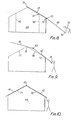
- FIGURES 6 and 7 show how quite a substantial cabin can be quickly and easily erected from such panels by two people.
- the cabin is shown diagrammatically in end view in FIGURE 6.
- the most difficult task is the lifting into position of the two panels 41 and 42 which are hinged together at the apex or ridge 43, but that can be done in the following way
- a central floor panel 44 is laid in its proper position on the foundation, and then a pair of fore-and-aft extending partition walls 45 and 46 are hinged to the bottom panel 44, at 47 and 48 by use of hinges described above.
- Each partition 45 or 46 is lifted by two men and hinged to the base panel 44 by longitudinal sliding. The two partitions are allowed to hinge over near to the ground where they rest on temporary props 49.
- the two roof ridge panels 41, 42 are hinged together at the ridge hinge 43 in a similar manner, and then they are hinged to the upper ends of the partitions 45 and 46 as indicated at 51 and 52. If necessary each of the ridge panels 41 and 42 can be hinged to its partition 45 or 46 in turn, the second ridge panel being simultaneously hinged at the ridge hinge and at the partition hinge 51 or 52.
- Front panel side extensions 57 are pivoted to the front panel 54 at 58, and side panels 59 are pivoted' to the panels 57 at 61, so that all the sides are laid out horizontally,pivoted together around the base panel 44.
- the panels 54, 57, and 59 are then lifted up by hinging about 55 until the front panel 54 is underneath, and supports, the ridge panels 41 and 42.
- the sides 59 are hinged about 61 to their correct position above the outer edge of the base sides 56 and they are then joined to corresponding side panels joined in a similar manner to the other end of the base panel 44.
- Windows, doors, and so on, as indicated at 62 can be included in the various front and side panels and partitions as required. In some circumstances the following method is simpler.
- the first roof ridge panel 41 is lifted up by two men, one at each side until its upper edge 71 is resting on the top corner of the/or each end panel 54. Then the roof ridge panel 41 is pushed up towards the position shown in FIGURE 8 by two men, one at each side, using the edge of the panel, or panels 54 as a guide, and possibly also the upper edge 73 of the partition.46.
- the other roof ridge panel 42 is hinged at 43 to the lower end of the roof ridge panel 41, and then the lower edge 74 of that panel is pushed by the end, shown at 75 in FIGURE 8, so that the two hinged roof ridge panels move up towards the position shown in FIGURE 9.
- the two hinged panels can be manipulated about the corner 72 as fulcrum for the panel 42, and the ridge point 76 as fulcrum for the panel 41 so that movement of the two panels can be controlled until with further pushing upwards and pivotting, the panel 41 can be lowered onto the edges 77 of the ends 54, and the panel 42 lowered onto the edges 78.
- roof ridge panels Once the roof ridge panels are in position and hinged together, they can be fixed to neighbouring vertical walls or partitions by any convenient brackets and indeed at any stage in the operation a panel can be supported by a strut having one hinge component at one end co-operating with the other hinge component on the panel, and after the roof is in the position shown in FIGURE 10, four or perhaps more such struts can be connected to roof panels and base, possibly through such hinges to retain the roof firmly in position against winds.
- the lower panels as indicated at 79 in FIGURE 6 can be hinged to the lower ends of the roof panels 41 and 42 in both methods of erecting, and secured in position by conventional means. It will be appreciated that those panels do not have to be lifted very high because they only have to connected to the lower edges 43 of the roof ridge panels.
Landscapes
- Engineering & Computer Science (AREA)
- Architecture (AREA)
- Physics & Mathematics (AREA)
- Electromagnetism (AREA)
- Civil Engineering (AREA)
- Structural Engineering (AREA)
- Mechanical Engineering (AREA)
- Conveying And Assembling Of Building Elements In Situ (AREA)
- Roof Covering Using Slabs Or Stiff Sheets (AREA)
- Extensible Doors And Revolving Doors (AREA)
- Specific Sealing Or Ventilating Devices For Doors And Windows (AREA)
Priority Applications (1)
| Application Number | Priority Date | Filing Date | Title |
|---|---|---|---|
| AT81302363T ATE12279T1 (de) | 1980-05-29 | 1981-05-28 | Scharnier. |
Applications Claiming Priority (4)
| Application Number | Priority Date | Filing Date | Title |
|---|---|---|---|
| GB8017572A GB2076884B (en) | 1980-05-29 | 1980-05-29 | Hinge |
| GB8017572 | 1980-05-29 | ||
| GB8115477 | 1981-05-20 | ||
| GB8115477A GB2077321A (en) | 1980-05-29 | 1981-05-20 | Cabin building |
Publications (3)
| Publication Number | Publication Date |
|---|---|
| EP0041800A2 true EP0041800A2 (de) | 1981-12-16 |
| EP0041800A3 EP0041800A3 (en) | 1982-02-03 |
| EP0041800B1 EP0041800B1 (de) | 1985-03-20 |
Family
ID=26275672
Family Applications (1)
| Application Number | Title | Priority Date | Filing Date |
|---|---|---|---|
| EP81302363A Expired EP0041800B1 (de) | 1980-05-29 | 1981-05-28 | Scharnier |
Country Status (3)
| Country | Link |
|---|---|
| EP (1) | EP0041800B1 (de) |
| DE (1) | DE3169350D1 (de) |
| GB (1) | GB2077321A (de) |
Cited By (3)
| Publication number | Priority date | Publication date | Assignee | Title |
|---|---|---|---|---|
| EP0127070A3 (de) * | 1983-05-31 | 1985-10-02 | VOLANI EBS S.p.A. | Transportable Wohneinheit von veränderlicher Kapazität |
| EP0203043A3 (en) * | 1985-05-21 | 1988-03-23 | Edil. Pro S.P.A | Improved transportable structure, apt to build up housesimproved transportable structure, apt to build up houses or other dwellings or other dwellings |
| DE3822446A1 (de) * | 1988-02-25 | 1989-09-07 | Dieter Knauer | Tragelement |
Families Citing this family (2)
| Publication number | Priority date | Publication date | Assignee | Title |
|---|---|---|---|---|
| NL8201996A (nl) * | 1982-05-13 | 1983-12-01 | D3Bn Adviesbureau Civ Ing | Werkwijze voor het bouwen van een huis uitgaande van een bouwpakket, hiervoor bestemd bouwpakket, werkwijze voor het maken van een fundering en een hierbij te gebruiken paalmuts. |
| GB8317663D0 (en) * | 1983-06-29 | 1983-08-03 | Cuthbert J D R | Floor and wall engagement means |
Family Cites Families (7)
| Publication number | Priority date | Publication date | Assignee | Title |
|---|---|---|---|---|
| DE6921480U (de) * | 1969-05-29 | 1969-10-02 | Vaw Ver Aluminium Werke Ag | Doppelwandige profilplatte |
| FR2211966A5 (de) * | 1972-12-21 | 1974-07-19 | Bonnet Henri | |
| GB1508122A (en) * | 1973-10-15 | 1978-04-19 | Cuthbert J | Hinge |
| FR2383345A1 (fr) * | 1977-03-11 | 1978-10-06 | Cegedur | Profiles emboites et clipes pour ridelles |
| GB2013751B (en) * | 1977-12-22 | 1982-05-06 | Cuthbert J D R | Folding cabin |
| GB1571853A (en) * | 1978-03-20 | 1980-07-23 | Bolton Gate Co Ltd | Guiding and retaining post for grilles shutters and the like |
| GB2031045B (en) * | 1978-08-31 | 1983-05-18 | Cuthbert J | Folding cabins |
-
1981
- 1981-05-20 GB GB8115477A patent/GB2077321A/en not_active Withdrawn
- 1981-05-28 EP EP81302363A patent/EP0041800B1/de not_active Expired
- 1981-05-28 DE DE8181302363T patent/DE3169350D1/de not_active Expired
Cited By (3)
| Publication number | Priority date | Publication date | Assignee | Title |
|---|---|---|---|---|
| EP0127070A3 (de) * | 1983-05-31 | 1985-10-02 | VOLANI EBS S.p.A. | Transportable Wohneinheit von veränderlicher Kapazität |
| EP0203043A3 (en) * | 1985-05-21 | 1988-03-23 | Edil. Pro S.P.A | Improved transportable structure, apt to build up housesimproved transportable structure, apt to build up houses or other dwellings or other dwellings |
| DE3822446A1 (de) * | 1988-02-25 | 1989-09-07 | Dieter Knauer | Tragelement |
Also Published As
| Publication number | Publication date |
|---|---|
| EP0041800B1 (de) | 1985-03-20 |
| EP0041800A3 (en) | 1982-02-03 |
| GB2077321A (en) | 1981-12-16 |
| DE3169350D1 (en) | 1985-04-25 |
Similar Documents
| Publication | Publication Date | Title |
|---|---|---|
| US4000588A (en) | Space-bounding sections for forming a building or part thereof, and methods of erecting such a building | |
| US3348344A (en) | Transportable building contruction with an extendable body structure | |
| EP0097475B1 (de) | Transportable, vorgefertigte Gebäude-Struktur | |
| US5966956A (en) | Portable refrigerated storage unit | |
| US5950373A (en) | Transportable structure kit | |
| US4373304A (en) | Prefabricated building units | |
| IE60765B1 (en) | Transportable construction element in the form of a container | |
| US20100018130A1 (en) | Collapsible Buildings And Building Modules | |
| US20030056446A1 (en) | Transportable building with higher roof | |
| WO1993020297A1 (en) | Portable shelter | |
| EP0041800A2 (de) | Scharnier | |
| GB2037838A (en) | A Foldable Prefabricated Building Structure | |
| US4242845A (en) | Connecting hinge system for prefabricated building foldable panel structures | |
| GB2085507A (en) | Buildings | |
| EP0688385B1 (de) | Modulare gebäudestruktur aus laminatplatten | |
| CA2227003A1 (en) | Collapsible building structures | |
| EP0135987A2 (de) | Verbindungsmittel für Fussboden und Wand | |
| JP2742843B2 (ja) | 蛇腹状折畳み自在構築物 | |
| GB2079808A (en) | Improvements in or relating to building structures | |
| DE102022000667B3 (de) | Transportable Wohneinheit | |
| JP2588452B2 (ja) | 仮設単体構築物 | |
| GB2062059A (en) | Method and means for building an insulating wall | |
| DE9404363U1 (de) | Dachgaube | |
| JP3138812B2 (ja) | 建築用連結パネル及びこれを使用した建築方法 | |
| US2639009A (en) | Greenhouse construction |
Legal Events
| Date | Code | Title | Description |
|---|---|---|---|
| PUAI | Public reference made under article 153(3) epc to a published international application that has entered the european phase |
Free format text: ORIGINAL CODE: 0009012 |
|
| PUAL | Search report despatched |
Free format text: ORIGINAL CODE: 0009013 |
|
| AK | Designated contracting states |
Designated state(s): AT BE CH DE FR GB IT LU NL SE |
|
| AK | Designated contracting states |
Designated state(s): AT BE CH DE FR GB IT LU NL SE |
|
| 17P | Request for examination filed |
Effective date: 19820608 |
|
| ITF | It: translation for a ep patent filed | ||
| GRAA | (expected) grant |
Free format text: ORIGINAL CODE: 0009210 |
|
| AK | Designated contracting states |
Designated state(s): AT BE CH DE FR GB IT LI LU NL SE |
|
| PG25 | Lapsed in a contracting state [announced via postgrant information from national office to epo] |
Ref country code: AT Effective date: 19850320 |
|
| REF | Corresponds to: |
Ref document number: 12279 Country of ref document: AT Date of ref document: 19850415 Kind code of ref document: T |
|
| PG25 | Lapsed in a contracting state [announced via postgrant information from national office to epo] |
Ref country code: SE Effective date: 19850330 |
|
| REF | Corresponds to: |
Ref document number: 3169350 Country of ref document: DE Date of ref document: 19850425 |
|
| ET | Fr: translation filed | ||
| PG25 | Lapsed in a contracting state [announced via postgrant information from national office to epo] |
Ref country code: LU Free format text: LAPSE BECAUSE OF NON-PAYMENT OF DUE FEES Effective date: 19850531 |
|
| PLBE | No opposition filed within time limit |
Free format text: ORIGINAL CODE: 0009261 |
|
| STAA | Information on the status of an ep patent application or granted ep patent |
Free format text: STATUS: NO OPPOSITION FILED WITHIN TIME LIMIT |
|
| 26N | No opposition filed | ||
| PGFP | Annual fee paid to national office [announced via postgrant information from national office to epo] |
Ref country code: NL Payment date: 19870531 Year of fee payment: 7 |
|
| ITTA | It: last paid annual fee | ||
| PG25 | Lapsed in a contracting state [announced via postgrant information from national office to epo] |
Ref country code: BE Effective date: 19890531 |
|
| PGFP | Annual fee paid to national office [announced via postgrant information from national office to epo] |
Ref country code: DE Payment date: 19890731 Year of fee payment: 9 |
|
| PGFP | Annual fee paid to national office [announced via postgrant information from national office to epo] |
Ref country code: FR Payment date: 19890808 Year of fee payment: 9 |
|
| PGFP | Annual fee paid to national office [announced via postgrant information from national office to epo] |
Ref country code: GB Payment date: 19890831 Year of fee payment: 9 |
|
| PGFP | Annual fee paid to national office [announced via postgrant information from national office to epo] |
Ref country code: CH Payment date: 19890927 Year of fee payment: 9 |
|
| PG25 | Lapsed in a contracting state [announced via postgrant information from national office to epo] |
Ref country code: NL Effective date: 19891201 |
|
| NLV4 | Nl: lapsed or anulled due to non-payment of the annual fee | ||
| PG25 | Lapsed in a contracting state [announced via postgrant information from national office to epo] |
Ref country code: GB Effective date: 19900528 |
|
| PG25 | Lapsed in a contracting state [announced via postgrant information from national office to epo] |
Ref country code: CH Effective date: 19900531 Ref country code: LI Effective date: 19900531 |
|
| GBPC | Gb: european patent ceased through non-payment of renewal fee | ||
| PG25 | Lapsed in a contracting state [announced via postgrant information from national office to epo] |
Ref country code: FR Effective date: 19910131 |
|
| REG | Reference to a national code |
Ref country code: CH Ref legal event code: PL |
|
| PG25 | Lapsed in a contracting state [announced via postgrant information from national office to epo] |
Ref country code: DE Effective date: 19910201 |
|
| REG | Reference to a national code |
Ref country code: FR Ref legal event code: ST |