EP0041925A2 - Boîte de vitesse pour un véhicule utilitaire - Google Patents
Boîte de vitesse pour un véhicule utilitaire Download PDFInfo
- Publication number
- EP0041925A2 EP0041925A2 EP81810220A EP81810220A EP0041925A2 EP 0041925 A2 EP0041925 A2 EP 0041925A2 EP 81810220 A EP81810220 A EP 81810220A EP 81810220 A EP81810220 A EP 81810220A EP 0041925 A2 EP0041925 A2 EP 0041925A2
- Authority
- EP
- European Patent Office
- Prior art keywords
- gear
- shaft
- transmission
- countershaft
- transmission according
- Prior art date
- Legal status (The legal status is an assumption and is not a legal conclusion. Google has not performed a legal analysis and makes no representation as to the accuracy of the status listed.)
- Granted
Links
Images

Classifications
-
- F—MECHANICAL ENGINEERING; LIGHTING; HEATING; WEAPONS; BLASTING
- F16—ENGINEERING ELEMENTS AND UNITS; GENERAL MEASURES FOR PRODUCING AND MAINTAINING EFFECTIVE FUNCTIONING OF MACHINES OR INSTALLATIONS; THERMAL INSULATION IN GENERAL
- F16H—GEARING
- F16H3/00—Toothed gearings for conveying rotary motion with variable gear ratio or for reversing rotary motion
- F16H3/02—Toothed gearings for conveying rotary motion with variable gear ratio or for reversing rotary motion without gears having orbital motion
- F16H3/20—Toothed gearings for conveying rotary motion with variable gear ratio or for reversing rotary motion without gears having orbital motion exclusively or essentially using gears that can be moved out of gear
- F16H3/36—Toothed gearings for conveying rotary motion with variable gear ratio or for reversing rotary motion without gears having orbital motion exclusively or essentially using gears that can be moved out of gear with a single gear meshable with any of a set of coaxial gears of different diameters
- F16H3/363—Toothed gearings for conveying rotary motion with variable gear ratio or for reversing rotary motion without gears having orbital motion exclusively or essentially using gears that can be moved out of gear with a single gear meshable with any of a set of coaxial gears of different diameters the teeth of the set of coaxial gears being arranged on a surface of generally conical shape
-
- F—MECHANICAL ENGINEERING; LIGHTING; HEATING; WEAPONS; BLASTING
- F16—ENGINEERING ELEMENTS AND UNITS; GENERAL MEASURES FOR PRODUCING AND MAINTAINING EFFECTIVE FUNCTIONING OF MACHINES OR INSTALLATIONS; THERMAL INSULATION IN GENERAL
- F16H—GEARING
- F16H3/00—Toothed gearings for conveying rotary motion with variable gear ratio or for reversing rotary motion
- F16H3/02—Toothed gearings for conveying rotary motion with variable gear ratio or for reversing rotary motion without gears having orbital motion
- F16H3/08—Toothed gearings for conveying rotary motion with variable gear ratio or for reversing rotary motion without gears having orbital motion exclusively or essentially with continuously meshing gears, that can be disengaged from their shafts
- F16H3/12—Toothed gearings for conveying rotary motion with variable gear ratio or for reversing rotary motion without gears having orbital motion exclusively or essentially with continuously meshing gears, that can be disengaged from their shafts with means for synchronisation not incorporated in the clutches
-
- F—MECHANICAL ENGINEERING; LIGHTING; HEATING; WEAPONS; BLASTING
- F16—ENGINEERING ELEMENTS AND UNITS; GENERAL MEASURES FOR PRODUCING AND MAINTAINING EFFECTIVE FUNCTIONING OF MACHINES OR INSTALLATIONS; THERMAL INSULATION IN GENERAL
- F16H—GEARING
- F16H3/00—Toothed gearings for conveying rotary motion with variable gear ratio or for reversing rotary motion
- F16H3/02—Toothed gearings for conveying rotary motion with variable gear ratio or for reversing rotary motion without gears having orbital motion
- F16H3/08—Toothed gearings for conveying rotary motion with variable gear ratio or for reversing rotary motion without gears having orbital motion exclusively or essentially with continuously meshing gears, that can be disengaged from their shafts
- F16H3/14—Gearings for reversal only
- F16H3/145—Gearings for reversal only with a pair of coaxial bevel gears, rotatable in opposite directions
-
- F—MECHANICAL ENGINEERING; LIGHTING; HEATING; WEAPONS; BLASTING
- F16—ENGINEERING ELEMENTS AND UNITS; GENERAL MEASURES FOR PRODUCING AND MAINTAINING EFFECTIVE FUNCTIONING OF MACHINES OR INSTALLATIONS; THERMAL INSULATION IN GENERAL
- F16H—GEARING
- F16H61/00—Control functions within control units of change-speed- or reversing-gearings for conveying rotary motion ; Control of exclusively fluid gearing, friction gearing, gearings with endless flexible members or other particular types of gearing
- F16H61/66—Control functions within control units of change-speed- or reversing-gearings for conveying rotary motion ; Control of exclusively fluid gearing, friction gearing, gearings with endless flexible members or other particular types of gearing specially adapted for continuously variable gearings
- F16H61/662—Control functions within control units of change-speed- or reversing-gearings for conveying rotary motion ; Control of exclusively fluid gearing, friction gearing, gearings with endless flexible members or other particular types of gearing specially adapted for continuously variable gearings with endless flexible members
Definitions
- the present invention relates to a manual transmission on a commercial vehicle, in particular a tractor.
- Known transmissions of this type are relatively cumbersome in construction, operation and maintenance, for example in that, in addition to a conventional manual transmission, a manual transmission is also provided (special print from truck / bus, issue 5/1967). Switching such a transmission is relatively cumbersome.
- the transmission not only has a large expenditure of individual parts, but the number of constantly rotating and thus energy-consuming gears is considerable, and the PTO drive, which is essential for commercial vehicles, is also uneconomical via the two existing gears.
- the main and countershafts of the gearboxes are arranged one above the other, which makes maintenance more difficult and results in a relatively high structure and thus high center of gravity of the gearbox and the vehicle.
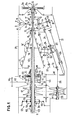
- FIG. 1 the end of the motor shaft 1 is shown, with which the one part 2a of a clutch is connected; the other part 2b of the coupling is connected to a hollow shaft 3.
- the shafts 1 and 3 each have a similar inner profile part 4, with which an outer profile part 5 of a central PTO shaft 6 can optionally be coupled by corresponding axial displacement of this PTO shaft.
- a hollow shift shaft 8 is coupled to the hollow shaft 3 in a longitudinally displaceable manner, but non-rotatably by means of a profile part 7.
- the shift lever 10 mounted at 9, with which the shift shaft can be displaced, engages this shift shaft.
- the forward gear is engaged, which is indicated by the designation V.
- a profile part 11 of the selector shaft 8 is in engagement with the hub of a bevel gear 12, via which a bevel gear 13 and a universal joint 14 an auxiliary shaft 15 is driven in the sense of the forward gear.
- a second profile part 16 of the shift shaft 8 comes into engagement with the hub of a bevel gear 17, while the profile part 11 comes out of engagement with the bevel gear 12.
- the shaft 15 is then driven in the sense of the reverse gear via the bevel gear 17 and the bevel gear 13 ben. In between is a neutral position of the shift lever or the shift shaft 8, designated 0 in FIG. 1, in which position the rotation of the shift shaft 8 is not transmitted to the shaft 15.
- Another position designated D of the shift lever 10 corresponds to a rear extreme position of the shift shaft 8, in which the profile part 11 is engaged with the front end of a conical step gear set 18 to be described and thus transmits the engine rotation directly to this gear set. For this position, there is also no direct drive from the selector shaft 8 to the auxiliary shaft 15.
- a bevel gear 19 which is axially displaceable but non-rotatable, which meshes with a bevel gear 20 on a countershaft 21.
- a spur gear 25 of the countershaft 24 can optionally be coupled to various wheels 18 1 of the wheel set 18.
- the shafts 21 and 24 are mounted in a frame 26, which is also indicated in FIG. 2, and which can be pivoted about a pivot axis 27.
- the pivoting position of the frame 26 is determined by a knee joint lever, the arms 28 and 29 of which are connected by the joint 30 and of which one pivotably engages the frame 26 and the other pivotally engages the gear housing or gear frame 31 indicated in FIGS. 1 and 2.
- a hydraulic actuating cylinder 33 engages between the toggle joint 30 and a further joint 32 on the frame 26. It is used in the switching operation, the toggle joint 28 to buckle 29 r 26 thereby pivoted outside the frame about its pivot axis 27 to and the gear 25 is disengaged from the gear 18 'of the wheel set 18th
- the countershaft 21 is practically parallel to the Mantelli never of the wheel set 18.
- a positioning fork 35 is attached to the frame 26, which can be brought into engagement in various positions with stop cams 36 of a stop shaft 37, which is fixedly arranged in the gear housing 31 and is not shown in FIG 25 clearly in engagement with a gear 18 'of the wheel set 18.
- the countershaft 21 is connected via a cardan shaft 38 to the one shaft 39 of a continuously variable toothed belt transmission.
- the switch positions of the frame 26 or the cylinder 34 are transmitted via a linkage 40 to disks 41 or 42 of the continuously variable toothed belt transmission.
- the gear ratio of the continuously variable toothed belt transmission is thus automatically adapted to the gear ratio in the actual manual transmission, that is, between the selector shaft 8 and the gear set 18.
- the wheel set 18 is seated on a hollow shaft 43 which surrounds the PTO shaft 6.
- the vehicle wheels are driven by the hollow shaft 43 via a switchable planetary gear 44, the driven wheel 45 of which is seated on a drive shaft 46 which can be connected to a front and rear wheel drive, as indicated schematically in FIG.
- a sun gear 47 on the shaft 43 of the planetary gear meshes with planet gears 48, which are mounted on the driven gear 49, which meshes with the driven gear 45.
- the planet gears 48 mesh with an outer ring gear 50, which can optionally be coupled to the shaft 43 via an engaged clutch 51 (FIG. 1 above) or to a fixed part 52 when the clutch 51 is disengaged.
- the entire planetary gear runs at the speed of the shaft 43 .mu.m, and there is a relatively fast, direct drive to the shaft 46. If the ring gear 50 is coupled to the fixed part 52, the planetary gear works as such and transmits the rotation of the shaft 43 to the shaft 46 with considerable reduction.
- a further planetary gear 53 is provided, the sun gear 54 of which is seated on a hollow shaft 55 surrounding the shaft 43, on which the pulley 42 and the other pulley of the continuously variable toothed belt transmission associated with it are also seated.
- a coupling piece to be longitudinally displaceable, but non-rotatable, which can be brought into engagement selectively either to the hollow shaft 55 (position F i gure 1 above) or with the frame 58 of the planetary gear 53 (position in Figure 1 below) . It is thus possible to couple the hollow shaft 55 to the hollow shaft 55 either directly or via the strong reduction of the planetary gear 53.
- the shaft 55 is coupled to the shaft 43 and the gear ratio of the continuously variable toothed belt transmission corresponds exactly to the gear ratio between the countershaft 21 and the gear set 18 New gear preselected, whereupon the clutch operation is triggered automatically when clutch 2 is disengaged.
- the cylinder 33 is first actuated, which kinks the toggle levers 28, 29 and thus causes the frame 26 and its axis 24 to pivot outwards.
- the gear 25 is thus disengaged from the gear 18 'of the gear set 18.
- the frame 26 is now unlocked by disengaging it by pivoting the previously effective stop cam 36 of the stop shaft 37 out of the fork 35.
- the frame 26 with the wheels 22, 23 and 25 is now moved along the countershaft 21 by means of the cylinder 34 into the new switching position moved where the fork 35 latches into the newly pivoted cam of the stop shaft 37 and thus precisely determines the position of the frame.
- This displacement of the frame 26 has been transmitted via the linkage 40 to the stepless toothed belt transmission, whereby the transmission ratio thereof has been changed in accordance with the translation of the new selected switching stage.
- the countershaft 21 and the wheels 22, 23 and 25 are now driven via the continuously variable transmission at a synchronized speed.
- the gear 25 can now be reinserted into one of the gears 18 'of the wheel set 18. After this process, the clutch 2 is finally engaged again, whereby the power flow from the engine via the transmission to the drive wheels is restored.
- a direct gear can be selected by switching off the actual manual transmission when the shift lever is brought into position D, in which case the selector shaft 8 is coupled directly to the wheel set 18 and via the same to the shaft 43.
- the reversing gear is switched off and the wheel 25 can preferably be disengaged from the wheel set 18 by controlling the cylinder 33.
- a third position of the Coupling part 57 may be provided, for which the shafts 43 and 55 are decoupled from one another and consequently the continuously variable transmission is also switched off. All auxiliary parts of the transmission would thus be at a standstill and there would only be a direct drive from the motor shaft to the shaft 43.
- the shift lever can be brought into the zero position, and the PTO shaft 6 can be displaced by means not shown, and can thus be engaged either directly with the motor shaft 1 or via the clutch 2 with the shaft 3.
- the transmission can be driven directly with the transmission completely stationary, without any transmission wheels being in motion.
- the planetary gear 53 allows the engagement of a creeper gear with stepless speed control.
- the gear 25 is disengaged by means of the cylinder 33, and the drive now takes place via the countershaft 21, the continuously variable transmission, the shaft 55, the planetary gear 53 and the coupling piece 57 on the shaft 43, which in turn is switched to the slow gear Planetary gear 44, which drives the vehicle's drive wheels.
- Very low driving speeds can be fine-tuned here.
- the setting of the continuously variable transmission can take place either by means of the switching movements of the cylinder 34 via the linkage 40 or via a special control linkage for the continuously variable transmission.
- One or the other of the planetary gear 44 and 53 can be omitted or can be replaced by another gear.
- a hydraulic clutch can be provided.
- the main transmission can have more or less than seven gear steps.
- the main gear is how already mentioned, easy to use, set up and work.
- a gearshift lever must be provided which can only be brought into four positions on one level. The switching positions can be preselected separately, and the planetary gears 44 and 53 can also be switched over separately.
- any special control of the continuously variable transmission can take place on a special operating element.
- the countershaft 21 and the cardan shaft 38 are preferably arranged horizontally next to the main axis of the transmission, which results in a low horizontal structure of the transmission. Such a transmission can be made easily accessible, so that it is also particularly favorable in terms of maintenance.
- the simplicity of manufacture results primarily from the dimensional equality of the most expensive parts, in particular the wheel set 18 for a complete type series.
- the gradation of the wheels is chosen, for example, so that there is an opening angle of 18 °. Even with stepped length of the wheel sets, this results in uniform machining per part type across the entire type series with largely the same set-up time programming, the same tool set and the same clamping device. At the same time, there are uniform axis distances, etc., which also facilitates the manufacture of the housing parts of the transmission.
- the planetary gear 44 or a corresponding change-over gear forms a unit together with the direct output to the rear and the front, and no feedback into the actual manual gearbox is necessary.
- the axis distances can be kept uniform for an entire row.
- the fully automatic switching process prevents incorrect operation.
- the process can take place very quickly, since there is a force-locking forced synchronization, which ultimately results in a largely uninterrupted flow of power, i.e. particularly short switching times allowed.
- the auxiliary shaft 15 can be arranged such that in the normal operating state according to FIG.
- the bevel gears 19 and 20 must enclose a correspondingly larger angle than 90 °.
- This solution also presupposes that the gear 20 is axially displaceably seated on the countershaft 21, but the advantage is that any irregularity in the transmission of motion in the normal operating state is excluded by the universal joint 14.
- the auxiliary shaft 15 only leaves its radial position during the switching process.
Landscapes
- Engineering & Computer Science (AREA)
- General Engineering & Computer Science (AREA)
- Mechanical Engineering (AREA)
- Structure Of Transmissions (AREA)
- Gear-Shifting Mechanisms (AREA)
- Arrangement Or Mounting Of Control Devices For Change-Speed Gearing (AREA)
- Arrangement Of Transmissions (AREA)
- Transmission Devices (AREA)
Priority Applications (1)
| Application Number | Priority Date | Filing Date | Title |
|---|---|---|---|
| AT81810220T ATE9030T1 (de) | 1980-06-06 | 1981-06-05 | Schaltgetriebe an einem nutzfahrzeug. |
Applications Claiming Priority (2)
| Application Number | Priority Date | Filing Date | Title |
|---|---|---|---|
| CH4375/80A CH654083A5 (de) | 1980-06-06 | 1980-06-06 | Schaltgetriebe an einem nutzfahrzeug. |
| CH4375/80 | 1980-06-06 |
Publications (3)
| Publication Number | Publication Date |
|---|---|
| EP0041925A2 true EP0041925A2 (fr) | 1981-12-16 |
| EP0041925A3 EP0041925A3 (en) | 1982-06-09 |
| EP0041925B1 EP0041925B1 (fr) | 1984-08-15 |
Family
ID=4274935
Family Applications (1)
| Application Number | Title | Priority Date | Filing Date |
|---|---|---|---|
| EP81810220A Expired EP0041925B1 (fr) | 1980-06-06 | 1981-06-05 | Boîte de vitesse pour un véhicule utilitaire |
Country Status (4)
| Country | Link |
|---|---|
| EP (1) | EP0041925B1 (fr) |
| AT (1) | ATE9030T1 (fr) |
| CH (1) | CH654083A5 (fr) |
| DE (1) | DE3165548D1 (fr) |
Cited By (8)
| Publication number | Priority date | Publication date | Assignee | Title |
|---|---|---|---|---|
| FR2678696A1 (fr) * | 1991-07-04 | 1993-01-08 | Renault | Boite de vitesses a variation continue entre deux rapports discrets. |
| WO1993001427A1 (fr) * | 1991-07-11 | 1993-01-21 | Luigi Celani | Boite de vitesses continue a engrenages helicoidaux |
| US7021168B2 (en) * | 2001-10-19 | 2006-04-04 | Zf Friedrichshafen Ag | Gearbox embodied with a layshaft |
| US7461570B2 (en) * | 2006-07-06 | 2008-12-09 | Mothaffar Hussain Y | Variable transmission using frusto-conical gears and sliding face gears |
| US8127636B2 (en) * | 2006-07-06 | 2012-03-06 | Mothaffar Hussain Y | Variable transmission for a motor vehicle |
| WO2014106950A1 (fr) * | 2013-01-06 | 2014-07-10 | Matsumura Hideki | Transmission à variation continue à engrenages |
| US9085619B2 (en) | 2007-11-30 | 2015-07-21 | Abbvie Biotechnology Ltd. | Anti-TNF antibody formulations |
| CN112173136A (zh) * | 2020-09-25 | 2021-01-05 | 中国直升机设计研究所 | 一种直升机用的发动机机械油门操作系统 |
Family Cites Families (11)
| Publication number | Priority date | Publication date | Assignee | Title |
|---|---|---|---|---|
| DE186422C (fr) * | 1906-07-18 | 1907-04-20 | ||
| FR380664A (fr) * | 1907-07-20 | 1907-12-14 | Richard Matthews Ruck | Mécanisme de changement de vitesse |
| US1338974A (en) * | 1918-08-23 | 1920-05-04 | Davisbournonville Company | Change-speed gearing |
| US1471162A (en) * | 1920-10-11 | 1923-10-16 | Iacobacci Domenico | Multiple-speed drive mechanism |
| US1453478A (en) * | 1921-04-25 | 1923-05-01 | Alden E Osborn | Cone-gear transmission mechanism |
| GB216544A (en) * | 1923-01-01 | 1924-06-02 | Edgar Fairweather | Improvements in variable speed toothed wheel gearing |
| US1528574A (en) * | 1924-07-03 | 1925-03-03 | Schaum Louis | Variable-speed-transmission mechanism |
| CH111842A (fr) * | 1924-10-07 | 1925-09-16 | Reid Wylie Robert William | Dispositif de changement de vitesse. |
| US1817819A (en) * | 1929-04-11 | 1931-08-04 | Healey Francis Jeremiah | Variable velocity ratio gearing |
| US3702571A (en) * | 1971-09-17 | 1972-11-14 | Jorge R Sainz | Variable speed transmission |
| EP0004412A1 (fr) * | 1978-01-21 | 1979-10-03 | GKN Transmissions Limited | Mécanisme de transmission à rapport variable |
-
1980
- 1980-06-06 CH CH4375/80A patent/CH654083A5/de not_active IP Right Cessation
-
1981
- 1981-06-05 AT AT81810220T patent/ATE9030T1/de not_active IP Right Cessation
- 1981-06-05 EP EP81810220A patent/EP0041925B1/fr not_active Expired
- 1981-06-05 DE DE8181810220T patent/DE3165548D1/de not_active Expired
Cited By (12)
| Publication number | Priority date | Publication date | Assignee | Title |
|---|---|---|---|---|
| FR2678696A1 (fr) * | 1991-07-04 | 1993-01-08 | Renault | Boite de vitesses a variation continue entre deux rapports discrets. |
| WO1993001427A1 (fr) * | 1991-07-11 | 1993-01-21 | Luigi Celani | Boite de vitesses continue a engrenages helicoidaux |
| US7021168B2 (en) * | 2001-10-19 | 2006-04-04 | Zf Friedrichshafen Ag | Gearbox embodied with a layshaft |
| US7461570B2 (en) * | 2006-07-06 | 2008-12-09 | Mothaffar Hussain Y | Variable transmission using frusto-conical gears and sliding face gears |
| US8127636B2 (en) * | 2006-07-06 | 2012-03-06 | Mothaffar Hussain Y | Variable transmission for a motor vehicle |
| US9085619B2 (en) | 2007-11-30 | 2015-07-21 | Abbvie Biotechnology Ltd. | Anti-TNF antibody formulations |
| US11167030B2 (en) | 2007-11-30 | 2021-11-09 | Abbvie Biotechnology Ltd | Protein formulations and methods of making same |
| US11191834B2 (en) | 2007-11-30 | 2021-12-07 | Abbvie Biotechnology Ltd | Protein formulations and methods of making same |
| WO2014106950A1 (fr) * | 2013-01-06 | 2014-07-10 | Matsumura Hideki | Transmission à variation continue à engrenages |
| JPWO2014106950A1 (ja) * | 2013-01-06 | 2017-01-19 | 松村 秀樹 | 歯車式無段変速機構 |
| CN112173136A (zh) * | 2020-09-25 | 2021-01-05 | 中国直升机设计研究所 | 一种直升机用的发动机机械油门操作系统 |
| CN112173136B (zh) * | 2020-09-25 | 2023-07-25 | 中国直升机设计研究所 | 一种直升机用的发动机机械油门操作系统 |
Also Published As
| Publication number | Publication date |
|---|---|
| EP0041925A3 (en) | 1982-06-09 |
| CH654083A5 (de) | 1986-01-31 |
| EP0041925B1 (fr) | 1984-08-15 |
| ATE9030T1 (de) | 1984-09-15 |
| DE3165548D1 (en) | 1984-09-20 |
Similar Documents
| Publication | Publication Date | Title |
|---|---|---|
| DE3822330C2 (fr) | ||
| EP0262625B1 (fr) | Procédé de changement de vitesse d'une transmission consistant en plusieurs unités de transmission | |
| EP0128319B1 (fr) | Boîte à vitesses avec marche arrière synchronisée | |
| DE102006054363A1 (de) | Lastschaltgetriebe | |
| DE3021254A1 (de) | Zapfwellenantriebseinrichtung fuer einen ackerschlepper | |
| DE2639000A1 (de) | Mechanisches mehrganggetriebe fuer fahrzeuge | |
| DE2328218A1 (de) | Schaltvorrichtung fuer ein wechselgetriebe | |
| DE3233931C2 (fr) | ||
| DE2643177C3 (de) | Zahnräderwechselgetriebe | |
| DE1530602A1 (de) | Sperrvorrichtung fuer Zahnraederwechselgetriebe von Kraftfahrzeugen,insbesondere Ackerschleppern | |
| DE2930950C2 (de) | Fahrzeugwechselgetriebe, insbesondere für Ackerschlepper | |
| EP0248899A1 (fr) | Boite de changement a echelonnement multiple de vitesses. | |
| DE2819220C2 (de) | Traktor-Getriebeanordnung | |
| EP0041925B1 (fr) | Boîte de vitesse pour un véhicule utilitaire | |
| DE1295268B (de) | Baumentastungsgeraet | |
| DE1530614C3 (de) | Zahnräderwechselgetriebe in Gruppenbauart für Ackerschlepper | |
| DE3236956C2 (fr) | ||
| DE1932332C3 (de) | Als Gruppengetriebe ausgebildetes Zahnräderwechselgetriebe für Fahrzeuge, insbesondere für landwirtschaftlich nutzbare Fahrzeuge | |
| DE2065300C3 (de) | Schaltvorrichtung für ein vorzugsweise in Gruppenbauart ausgeführtes Zahnräderwechselgetriebe für Fahrzeuge | |
| EP0353698B1 (fr) | Dispositif d'entraînement pour véhicules automobiles | |
| DE2601113A1 (de) | Stirnrad-wechselgetriebe fuer raupenfahrzeuge | |
| DE949713C (de) | Schaltvorrichtung fuer Ackerschlepper | |
| DE2346116B2 (de) | Zahnräderwechselgetriebe in Gruppenbauweise, insbesondere für land- und? oder bauwirtschaftlich nutzbare Kraftfahrzeuge | |
| DE644947C (de) | Zahnraederwechselgetriebe, insbesondere fuer Kraftfahrzeuge | |
| DE1198213B (de) | Kraftfahrzeuggetriebe |
Legal Events
| Date | Code | Title | Description |
|---|---|---|---|
| PUAI | Public reference made under article 153(3) epc to a published international application that has entered the european phase |
Free format text: ORIGINAL CODE: 0009012 |
|
| AK | Designated contracting states |
Designated state(s): AT BE DE FR GB IT LU NL SE |
|
| PUAL | Search report despatched |
Free format text: ORIGINAL CODE: 0009013 |
|
| AK | Designated contracting states |
Designated state(s): AT BE DE FR GB IT LU NL SE |
|
| 17P | Request for examination filed |
Effective date: 19821208 |
|
| ITF | It: translation for a ep patent filed | ||
| GRAA | (expected) grant |
Free format text: ORIGINAL CODE: 0009210 |
|
| AK | Designated contracting states |
Designated state(s): AT BE DE FR GB IT LU NL SE |
|
| REF | Corresponds to: |
Ref document number: 9030 Country of ref document: AT Date of ref document: 19840915 Kind code of ref document: T |
|
| REF | Corresponds to: |
Ref document number: 3165548 Country of ref document: DE Date of ref document: 19840920 |
|
| ET | Fr: translation filed | ||
| PLBE | No opposition filed within time limit |
Free format text: ORIGINAL CODE: 0009261 |
|
| STAA | Information on the status of an ep patent application or granted ep patent |
Free format text: STATUS: NO OPPOSITION FILED WITHIN TIME LIMIT |
|
| PG25 | Lapsed in a contracting state [announced via postgrant information from national office to epo] |
Ref country code: LU Free format text: LAPSE BECAUSE OF NON-PAYMENT OF DUE FEES Effective date: 19850630 |
|
| 26N | No opposition filed | ||
| PGFP | Annual fee paid to national office [announced via postgrant information from national office to epo] |
Ref country code: AT Payment date: 19860630 Year of fee payment: 6 |
|
| PGFP | Annual fee paid to national office [announced via postgrant information from national office to epo] |
Ref country code: NL Payment date: 19870630 Year of fee payment: 7 |
|
| PG25 | Lapsed in a contracting state [announced via postgrant information from national office to epo] |
Ref country code: GB Effective date: 19880605 |
|
| PG25 | Lapsed in a contracting state [announced via postgrant information from national office to epo] |
Ref country code: NL Effective date: 19890101 |
|
| NLV4 | Nl: lapsed or anulled due to non-payment of the annual fee | ||
| GBPC | Gb: european patent ceased through non-payment of renewal fee | ||
| PG25 | Lapsed in a contracting state [announced via postgrant information from national office to epo] |
Ref country code: AT Effective date: 19890605 |
|
| PG25 | Lapsed in a contracting state [announced via postgrant information from national office to epo] |
Ref country code: SE Effective date: 19890606 |
|
| PG25 | Lapsed in a contracting state [announced via postgrant information from national office to epo] |
Ref country code: BE Effective date: 19890630 |
|
| BERE | Be: lapsed |
Owner name: WUTHRICH HANSRUDOLF Effective date: 19890630 |
|
| PG25 | Lapsed in a contracting state [announced via postgrant information from national office to epo] |
Ref country code: FR Free format text: LAPSE BECAUSE OF NON-PAYMENT OF DUE FEES Effective date: 19900228 |
|
| PG25 | Lapsed in a contracting state [announced via postgrant information from national office to epo] |
Ref country code: DE Effective date: 19900301 |
|
| REG | Reference to a national code |
Ref country code: FR Ref legal event code: ST |
|
| EUG | Se: european patent has lapsed |
Ref document number: 81810220.4 Effective date: 19900412 |