EP0042011B1 - Dispositif pour la fabrication de tubes par enroulement hélicoidal d'une bande de préférence ondulée - Google Patents
Dispositif pour la fabrication de tubes par enroulement hélicoidal d'une bande de préférence ondulée Download PDFInfo
- Publication number
- EP0042011B1 EP0042011B1 EP80105664A EP80105664A EP0042011B1 EP 0042011 B1 EP0042011 B1 EP 0042011B1 EP 80105664 A EP80105664 A EP 80105664A EP 80105664 A EP80105664 A EP 80105664A EP 0042011 B1 EP0042011 B1 EP 0042011B1
- Authority
- EP
- European Patent Office
- Prior art keywords
- rollers
- entry
- band
- roller
- rotation
- Prior art date
- Legal status (The legal status is an assumption and is not a legal conclusion. Google has not performed a legal analysis and makes no representation as to the accuracy of the status listed.)
- Expired
Links
Images
Classifications
-
- B—PERFORMING OPERATIONS; TRANSPORTING
- B21—MECHANICAL METAL-WORKING WITHOUT ESSENTIALLY REMOVING MATERIAL; PUNCHING METAL
- B21C—MANUFACTURE OF METAL SHEETS, WIRE, RODS, TUBES, PROFILES OR LIKE SEMI-MANUFACTURED PRODUCTS OTHERWISE THAN BY ROLLING; AUXILIARY OPERATIONS USED IN CONNECTION WITH METAL-WORKING WITHOUT ESSENTIALLY REMOVING MATERIAL
- B21C37/00—Manufacture of metal sheets, rods, wire, tubes, profiles or like semi-manufactured products, not otherwise provided for; Manufacture of tubes of special shape
- B21C37/06—Manufacture of metal sheets, rods, wire, tubes, profiles or like semi-manufactured products, not otherwise provided for; Manufacture of tubes of special shape of tubes or metal hoses; Combined procedures for making tubes, e.g. for making multi-wall tubes
- B21C37/12—Making tubes or metal hoses with helically arranged seams
- B21C37/124—Making tubes or metal hoses with helically arranged seams the tubes having a special shape, e.g. with corrugated wall, flexible tubes
Definitions
- the invention relates to a device for the production of pipes by helical winding of a preferably corrugated band with a winding device of circularly arranged on the outer circumference of the pipe to be wound, freely rotatable support rollers, their axes of rotation parallel to one another and to the longitudinal axis of the pipe to be wound on a common carrier plate are arranged, with two arranged at the entry point of the tape in the winding device, acting on the two broad sides of the tape, the mutual connection of the adjacent tape winding effecting drivable in the tube and with two spaced in front of the inlet roller pair, also on the broad sides of the Belt attacking drive rollers, wherein the central axis running through the center of the circle formed by the support rollers and parallel to the axes of rotation of the support rollers, the plane determined by the axes of rotation of the inlet rollers in the pitch angle of the pipe to be wound.
- the object of the present invention is therefore to propose a device of the type mentioned at the outset which in a simple manner ensures a constant tube diameter of the tubes to be produced.
- a belt guide is arranged between the inlet rollers and drive rollers, that a bending roller is arranged between the belt guide and inlet rollers, which projects beyond the connecting line between the inlet point of the belt into the inlet roller pair and the belt guide in the direction of the central axis of the winding device, and that the peripheral speed of the inner infeed roller arranged inside the winding device is lower than the peripheral speed of the outer infeed roller arranged outside the winding device.
- the inner infeed roller advantageously has a smaller diameter than the outer infeed roller.
- the slip of the inner feed roller with respect to the outer feed roller is preferably 0.2 to 0.5 mm per revolution of the inner feed roller.
- the carrier plate is arranged such that the central axis intersects the plane determined by the axes of rotation of the inlet rollers in the intersection line of this plane with the plane running through the center of the inlet rollers and perpendicular to the axes of rotation of the inlet rollers.
- the carrier plate preferably has a contact surface which is inclined at an angle of 90 ° to the central axis and which is inclined by the pitch angle of the tube to be wound and which bears on a holding surface perpendicular to the axes of rotation of the feed rollers, and is the carrier plate in the winding direction of the band around the central axis in this way rotated arranged that the line of intersection of the plane of the contact surface with a plane perpendicular to the central axis intersects the plane extending through the axes of rotation of the feed rollers at an acute cutting angle.
- the cutting angle is preferably 0.5 to 1.5 °.
- the carrier plate is advantageously circular.
- the carrier plate is preferably releasably attached to the holding surface.
- the peripheral speed of the drive rollers is advantageously greater than the peripheral speed of the outer feed roller.
- the slip of the drive rollers to the outer feed roller is preferably 0.2 to 0.5 mm per revolution of the drive rollers.
- the bending roller is preferably rotatable about an axis of rotation parallel to the axes of rotation of the feed roller.
- the bending roller is advantageously displaceable and fixable in the direction of the central axis.
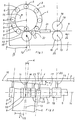
- a holder 1 has a holding surface 2, on which a winding device 3 is arranged.
- the winding device 3 has an annular support plate 4, which carries annularly arranged, freely rotatable support rollers 5 on the outer circumference of the tube to be wound, the axes of rotation 6 of which are parallel to one another.
- the central axis 7 running through the center M of the circle formed by the axes of rotation 6 of the support rollers 5 and parallel to the axes of rotation 6 of the support rollers is equal to the central longitudinal axis of the tube to be wound.
- two inlet rollers 9 and 10 are arranged which can be driven and which act on the two broad sides of the band.
- the inner infeed roller 9 is arranged inside the winding device 3, while the outer infeed roller 10 is arranged outside the winding device.
- the infeed rollers are rotatable about axes of rotation 11 perpendicular to the holding surface 2 and driven by a drive device, not shown.
- the inner feed roller 9 has a lower peripheral speed than the outer feed roller 10.
- the carrier plate 4 has an abutment surface 12 which extends to the central axis 7 at an angle of 90 ° by the pitch angle ⁇ of the pipe to be wound and which bears on the holding surface 2, so that the axes of rotation 6 of the Support rollers 5 or the central axis 7 intersect the plane designated by 13, determined by the axes of rotation 11 of the inlet rollers 9 and 10, in the pitch angle ⁇ .
- the carrier plate 4 is arranged on the holding surface 2 such that the central axis 7, the plane determined by the axes of rotation 11 of the inlet rollers 9, 10, designated by 13 in the line of intersection of this plane with that through the center of the inlet rollers 9 and 10, perpendicular to the axes of rotation 11 of the infeed rollers run, 14 designated plane intersects.
- the band 8 to be wound runs symmetrically to this plane, which is designated by 14.
- the carrier plate 4 is arranged rotated about the central axis 7 in the winding direction indicated by the arrow 15 in such a way that the intersection line of the contact surface 12 designated with 16 has a plane perpendicular to the central axis 7 (in FIG. 2, for example the plane denoted by 17) which intersects the plane denoted by 13 through the axes of rotation 11 of the inlet rollers 9 and 10 and intersects at an acute cutting angle.
- two drive rollers 18 are arranged on the holder 1, which also act on the broad sides of the belt 8.
- the drivable drive rollers 18 are rotatable about axes of rotation 19 perpendicular to the holding surface 2, the plane running through the axes of rotation 19, designated by 20, running parallel to the plane designated by 13 through the axes of rotation 11 of the feed rollers 9 and 10.
- a belt guide 21 is arranged between the drive rollers 18 and inlet rollers 9 and 10. The peripheral speed of the drive rollers 18 is greater than the peripheral speed of the outer feed roller 10.
- a bending roller 22 is arranged, which can be rotated about an axis of rotation 23 perpendicular to the contact surface 2 and is displaceable and fixable on the holder in the direction of the central axis 7.
- the bending roller 22 is set such that it projects beyond the connecting line between the entry point and the belt guide 21 in the direction of the central axis 7, as shown in FIG. 1.
- the band In the manufacture of a tube by helically winding the band 8, the band is first fed in the direction of the arrow labeled 24 to the drive rollers 18, which feed it through the band guide 21 and via the bending roller 22 to the inlet roller pair 9 and 10 of the winding device 3.
- the band 8 In the winding device, the band 8 is wound helically to form a tube, the feed rollers 9 and 10 establishing the connection of the incoming band with the tube that has already been wound.
- the wound tube is withdrawn from the winding device 3 in the direction of the arrow labeled 25.
- the peripheral speed of the inner infeed roller is less than the peripheral speed of the outer infeed roller, a secure guiding of the belt between the infeed rollers is ensured and the belt to be wikkeinde pressed firmly against the support rollers 5 of the winding device 3, so that the belt or the tube is held securely in the winding device 3 and high working speeds are possible.
- This effect is reinforced by the fact that the peripheral speed of the drive rollers 18 is greater than the peripheral speed of the outer feed roller 10.
- the ring-shaped carrier plate 4 is releasably attached to the holding surface 2 of the holder 1, so that another winding device with the corresponding diameter can be fastened to the holder 1 in order to produce a tube with a different diameter.
- the fact that the inner feed roller 9 has a very small diameter not only facilitates the bending work, but it is also possible to produce tubes with a very small diameter.
Landscapes
- Engineering & Computer Science (AREA)
- Mechanical Engineering (AREA)
- Shaping Of Tube Ends By Bending Or Straightening (AREA)
Claims (9)
Priority Applications (1)
| Application Number | Priority Date | Filing Date | Title |
|---|---|---|---|
| AT80105664T ATE7464T1 (de) | 1980-06-16 | 1980-09-20 | Vorrichtung zum herstellen von rohren durch schraubenlinienfoermiges wickeln eines vorzugsweise gewellten bandes. |
Applications Claiming Priority (2)
| Application Number | Priority Date | Filing Date | Title |
|---|---|---|---|
| DE3022575 | 1980-06-16 | ||
| DE19803022575 DE3022575C3 (de) | 1980-06-16 | 1980-06-16 | Vorrichtung zum Herstellen von Rohren durch schraubenlinienförmiges Wickeln eines vorzugsweise gewellten Bandes |
Publications (3)
| Publication Number | Publication Date |
|---|---|
| EP0042011A2 EP0042011A2 (fr) | 1981-12-23 |
| EP0042011A3 EP0042011A3 (en) | 1982-04-14 |
| EP0042011B1 true EP0042011B1 (fr) | 1984-05-16 |
Family
ID=6104763
Family Applications (1)
| Application Number | Title | Priority Date | Filing Date |
|---|---|---|---|
| EP80105664A Expired EP0042011B1 (fr) | 1980-06-16 | 1980-09-20 | Dispositif pour la fabrication de tubes par enroulement hélicoidal d'une bande de préférence ondulée |
Country Status (2)
| Country | Link |
|---|---|
| EP (1) | EP0042011B1 (fr) |
| AT (1) | ATE7464T1 (fr) |
Families Citing this family (2)
| Publication number | Priority date | Publication date | Assignee | Title |
|---|---|---|---|---|
| DE3540125C3 (de) * | 1985-11-13 | 1997-05-07 | Hahn Fritz Gmbh Co Kg | Verfahren und Vorrichtung zum Herstellen eines Wellrohres durch schraubenlinienförmiges Wickeln eines gewellten, dünnen Bandes, vorzugsweise eines Stahlbandes |
| GB2433453B (en) | 2005-12-23 | 2010-08-11 | Iti Scotland Ltd | An apparatus for and method of manfacturing helically wound structures |
Family Cites Families (3)
| Publication number | Priority date | Publication date | Assignee | Title |
|---|---|---|---|---|
| DE1602342A1 (de) * | 1967-05-11 | 1971-08-26 | Protol S A | Rohr mit schraubenfoermig verlaufender Falznaht |
| DE2154438C3 (de) * | 1971-11-02 | 1980-12-18 | Institut Elektrosvarki Imeni E.O. Patona Akademii Nauk Ukrainskoj Ssr, Kiew (Sowjetunion) | Schraubennaht-Rohrwerk |
| DE2760262C1 (de) * | 1976-12-23 | 1985-11-14 | Emil 6603 Sulzbach Siegwart | Vorrichtung zum Herstellen von Rohren |
-
1980
- 1980-09-20 EP EP80105664A patent/EP0042011B1/fr not_active Expired
- 1980-09-20 AT AT80105664T patent/ATE7464T1/de not_active IP Right Cessation
Also Published As
| Publication number | Publication date |
|---|---|
| EP0042011A2 (fr) | 1981-12-23 |
| EP0042011A3 (en) | 1982-04-14 |
| ATE7464T1 (de) | 1984-06-15 |
Similar Documents
| Publication | Publication Date | Title |
|---|---|---|
| DE2163649C2 (de) | Vorrichtung zur Herstellung schraubenförmig gewellter Drähte | |
| DE2253291A1 (de) | Vorrichtung zum antreiben und richten eines schweissdrahts | |
| DE2327846C3 (de) | Vorrichtung zum Abrichten einer Schleifscheibe | |
| EP0515802B1 (fr) | Appareil pour la fabrication de tubes à jonction hélicoidale à partir d'une bande métallique | |
| EP0042011B1 (fr) | Dispositif pour la fabrication de tubes par enroulement hélicoidal d'une bande de préférence ondulée | |
| DE2642583A1 (de) | Schweissmaschine zum verbinden von bandstahlabschnitten oder -rollen | |
| DE2009509A1 (de) | Maschine zur kontinuierlichen Her stellung von Bewehrungskörben für Stahlbeton-Pfähle, -Masten oder dergl | |
| DE2210055C3 (de) | Verfahren zum Verbinden aneinanderliegender Ränder von Blechen durch Falzen | |
| DE3022575C2 (fr) | ||
| CH620607A5 (en) | Device for the production of helically seamed and perforated tubes | |
| CH639571A5 (de) | Vorrichtung zur kontinuierlichen herstellung von rohren aus spiralfoermig aufgewundenen streifen. | |
| DE3104356A1 (de) | "maschineneinrichtung zum kerben, messen, abtasten und ablaengen von materialien" | |
| DE2806973C2 (de) | Vorrichtung zum Aufbringen von Strangabschnitten auf einen Rotationskörper | |
| DE2428111A1 (de) | Verfahren und vorrichtung zum saegen von werkstuecken | |
| DE2359368A1 (de) | Verfahren und vorrichtung zur herstellung von verstaerkungselementen kurzer laengenausdehnung | |
| DE2255864A1 (de) | Vorrichtung zum abschneiden von ringen von einem schlauch oder dergleichen | |
| DE2249312B2 (de) | Verfahren und Vorrichtung zur Herstellung eines Standers fur dynamoelektrische Maschinen | |
| EP0081452A1 (fr) | Procédé et dispositif pour laminer à froid des tubes, en particulier des tubes de grande longueur | |
| DE3116990A1 (de) | Maschine zur herstellung von schraubenfoermig gewickelten blechrohren | |
| DE4124618C2 (de) | Vorrichtung zur Herstellung geschweißter Profilrohre | |
| DE19709733A1 (de) | Vorrichtung zum rotierenden Richten von Draht | |
| DE2719084A1 (de) | Vorrichtung zum fortlaufenden glattwalzen von stabenden | |
| DE1629770C2 (de) | Vorrichtung zum Herstellen eines glasfaserverstärkten Kunststoffrohres oder rohrähnlichen Formkörpers | |
| AT164284B (de) | Gewindewalzmaschine | |
| DE1948672C (de) | Abstreifvorrichtung für den aus einem Gießrad austretenden Strang |
Legal Events
| Date | Code | Title | Description |
|---|---|---|---|
| PUAI | Public reference made under article 153(3) epc to a published international application that has entered the european phase |
Free format text: ORIGINAL CODE: 0009012 |
|
| AK | Designated contracting states |
Designated state(s): AT BE CH FR GB IT LU NL SE |
|
| PUAL | Search report despatched |
Free format text: ORIGINAL CODE: 0009013 |
|
| AK | Designated contracting states |
Designated state(s): AT BE CH FR GB IT LU NL SE |
|
| 17P | Request for examination filed |
Effective date: 19820423 |
|
| R17P | Request for examination filed (corrected) |
Effective date: 19820423 |
|
| ITF | It: translation for a ep patent filed | ||
| GRAA | (expected) grant |
Free format text: ORIGINAL CODE: 0009210 |
|
| AK | Designated contracting states |
Designated state(s): AT BE CH FR GB IT LI LU NL SE |
|
| REF | Corresponds to: |
Ref document number: 7464 Country of ref document: AT Date of ref document: 19840615 Kind code of ref document: T |
|
| ET | Fr: translation filed | ||
| PLBE | No opposition filed within time limit |
Free format text: ORIGINAL CODE: 0009261 |
|
| STAA | Information on the status of an ep patent application or granted ep patent |
Free format text: STATUS: NO OPPOSITION FILED WITHIN TIME LIMIT |
|
| 26N | No opposition filed | ||
| ITTA | It: last paid annual fee | ||
| EPTA | Lu: last paid annual fee | ||
| EAL | Se: european patent in force in sweden |
Ref document number: 80105664.9 |
|
| PGFP | Annual fee paid to national office [announced via postgrant information from national office to epo] |
Ref country code: GB Payment date: 19980817 Year of fee payment: 19 |
|
| PGFP | Annual fee paid to national office [announced via postgrant information from national office to epo] |
Ref country code: LU Payment date: 19980820 Year of fee payment: 19 Ref country code: BE Payment date: 19980820 Year of fee payment: 19 |
|
| PGFP | Annual fee paid to national office [announced via postgrant information from national office to epo] |
Ref country code: SE Payment date: 19980821 Year of fee payment: 19 Ref country code: NL Payment date: 19980821 Year of fee payment: 19 Ref country code: FR Payment date: 19980821 Year of fee payment: 19 Ref country code: CH Payment date: 19980821 Year of fee payment: 19 Ref country code: AT Payment date: 19980821 Year of fee payment: 19 |
|
| PG25 | Lapsed in a contracting state [announced via postgrant information from national office to epo] |
Ref country code: LU Free format text: LAPSE BECAUSE OF NON-PAYMENT OF DUE FEES Effective date: 19990920 Ref country code: GB Free format text: LAPSE BECAUSE OF NON-PAYMENT OF DUE FEES Effective date: 19990920 Ref country code: AT Free format text: LAPSE BECAUSE OF NON-PAYMENT OF DUE FEES Effective date: 19990920 |
|
| PG25 | Lapsed in a contracting state [announced via postgrant information from national office to epo] |
Ref country code: SE Free format text: THE PATENT HAS BEEN ANNULLED BY A DECISION OF A NATIONAL AUTHORITY Effective date: 19990929 |
|
| PG25 | Lapsed in a contracting state [announced via postgrant information from national office to epo] |
Ref country code: LI Free format text: LAPSE BECAUSE OF NON-PAYMENT OF DUE FEES Effective date: 19990930 Ref country code: CH Free format text: LAPSE BECAUSE OF NON-PAYMENT OF DUE FEES Effective date: 19990930 Ref country code: BE Free format text: LAPSE BECAUSE OF NON-PAYMENT OF DUE FEES Effective date: 19990930 |
|
| BERE | Be: lapsed |
Owner name: FRITZ HAHN K.G. Effective date: 19990930 |
|
| PG25 | Lapsed in a contracting state [announced via postgrant information from national office to epo] |
Ref country code: NL Free format text: LAPSE BECAUSE OF NON-PAYMENT OF DUE FEES Effective date: 20000401 |
|
| GBPC | Gb: european patent ceased through non-payment of renewal fee |
Effective date: 19990920 |
|
| EUG | Se: european patent has lapsed |
Ref document number: 80105664.9 |
|
| REG | Reference to a national code |
Ref country code: CH Ref legal event code: PL |
|
| PG25 | Lapsed in a contracting state [announced via postgrant information from national office to epo] |
Ref country code: FR Free format text: LAPSE BECAUSE OF NON-PAYMENT OF DUE FEES Effective date: 20000531 |
|
| NLV4 | Nl: lapsed or anulled due to non-payment of the annual fee |
Effective date: 20000401 |
|
| REG | Reference to a national code |
Ref country code: FR Ref legal event code: ST |