EP0042086A2 - Vorrichtung zur Bestimmung des aktiven Sauerstoffgehaltes von Metallschmelzen - Google Patents
Vorrichtung zur Bestimmung des aktiven Sauerstoffgehaltes von Metallschmelzen Download PDFInfo
- Publication number
- EP0042086A2 EP0042086A2 EP81104035A EP81104035A EP0042086A2 EP 0042086 A2 EP0042086 A2 EP 0042086A2 EP 81104035 A EP81104035 A EP 81104035A EP 81104035 A EP81104035 A EP 81104035A EP 0042086 A2 EP0042086 A2 EP 0042086A2
- Authority
- EP
- European Patent Office
- Prior art keywords
- zirconium oxide
- mass
- tube
- protective screen
- covering
- Prior art date
- Legal status (The legal status is an assumption and is not a legal conclusion. Google has not performed a legal analysis and makes no representation as to the accuracy of the status listed.)
- Granted
Links
- QVGXLLKOCUKJST-UHFFFAOYSA-N atomic oxygen Chemical compound [O] QVGXLLKOCUKJST-UHFFFAOYSA-N 0.000 title claims abstract description 4
- 239000001301 oxygen Substances 0.000 title claims abstract description 4
- 229910052760 oxygen Inorganic materials 0.000 title claims abstract description 4
- 229910052751 metal Inorganic materials 0.000 title abstract description 6
- 239000002184 metal Substances 0.000 title abstract description 6
- 150000002739 metals Chemical class 0.000 title 1
- 229910001928 zirconium oxide Inorganic materials 0.000 claims abstract description 41
- RVTZCBVAJQQJTK-UHFFFAOYSA-N oxygen(2-);zirconium(4+) Chemical compound [O-2].[O-2].[Zr+4] RVTZCBVAJQQJTK-UHFFFAOYSA-N 0.000 claims abstract description 40
- 230000001681 protective effect Effects 0.000 claims abstract description 23
- 239000000919 ceramic Substances 0.000 claims abstract description 12
- 230000035515 penetration Effects 0.000 claims abstract description 5
- 239000003292 glue Substances 0.000 claims abstract 2
- 229920002379 silicone rubber Polymers 0.000 claims abstract 2
- 239000004945 silicone rubber Substances 0.000 claims abstract 2
- 239000000126 substance Substances 0.000 claims description 6
- XEEYBQQBJWHFJM-UHFFFAOYSA-N Iron Chemical compound [Fe] XEEYBQQBJWHFJM-UHFFFAOYSA-N 0.000 claims description 4
- 239000004568 cement Substances 0.000 claims description 4
- 239000011261 inert gas Substances 0.000 claims description 3
- 229910001018 Cast iron Inorganic materials 0.000 claims description 2
- 238000010438 heat treatment Methods 0.000 claims description 2
- 229910052742 iron Inorganic materials 0.000 claims description 2
- 239000000161 steel melt Substances 0.000 claims description 2
- 229910010293 ceramic material Inorganic materials 0.000 claims 1
- 238000004519 manufacturing process Methods 0.000 claims 1
- 239000000155 melt Substances 0.000 abstract description 3
- 150000001875 compounds Chemical class 0.000 description 3
- 239000004020 conductor Substances 0.000 description 3
- 238000005259 measurement Methods 0.000 description 3
- XKRFYHLGVUSROY-UHFFFAOYSA-N Argon Chemical compound [Ar] XKRFYHLGVUSROY-UHFFFAOYSA-N 0.000 description 2
- 239000011248 coating agent Substances 0.000 description 2
- 238000000576 coating method Methods 0.000 description 2
- ZOKXTWBITQBERF-UHFFFAOYSA-N Molybdenum Chemical compound [Mo] ZOKXTWBITQBERF-UHFFFAOYSA-N 0.000 description 1
- 229910052786 argon Inorganic materials 0.000 description 1
- 229940125898 compound 5 Drugs 0.000 description 1
- 239000000203 mixture Substances 0.000 description 1
- 230000001590 oxidative effect Effects 0.000 description 1
- TWNQGVIAIRXVLR-UHFFFAOYSA-N oxo(oxoalumanyloxy)alumane Chemical compound O=[Al]O[Al]=O TWNQGVIAIRXVLR-UHFFFAOYSA-N 0.000 description 1
- 230000035939 shock Effects 0.000 description 1
- -1 zirconium oxide compound Chemical class 0.000 description 1
Images
Classifications
-
- G—PHYSICS
- G01—MEASURING; TESTING
- G01N—INVESTIGATING OR ANALYSING MATERIALS BY DETERMINING THEIR CHEMICAL OR PHYSICAL PROPERTIES
- G01N27/00—Investigating or analysing materials by the use of electric, electrochemical, or magnetic means
- G01N27/26—Investigating or analysing materials by the use of electric, electrochemical, or magnetic means by investigating electrochemical variables; by using electrolysis or electrophoresis
- G01N27/403—Cells and electrode assemblies
- G01N27/406—Cells and probes with solid electrolytes
- G01N27/411—Cells and probes with solid electrolytes for investigating or analysing of liquid metals
- G01N27/4118—Means for protecting the electrolyte or the electrodes
Definitions
- the invention relates to a device for determining the active oxygen content of cast iron, iron or steel melts with a measuring head attached to the end of a support tube made of a ceramic mass, in which an electro-chemical cell consisting of a zirconium oxide mass and a reference mass is arranged, which is equipped with a Protective screen is provided, which shields the electro-chemical cell from the melt and is destroyed when the measuring head is immersed in the metal melt.
- the protective screen also being tubular and at least the same length as the section of the tube consisting of the zirconium oxide mass, which protrudes from the ceramic mass, is provided that the tube forming the protective screen can be pushed onto the tube consisting of the zirconium oxide composition and the inner diameter of the protective screen practically corresponds to the outer diameter of the tube, so that the protective screen on the electro chemical cell fits tightly.
- the zirconium oxide compound has the shape of a disk which rests on the reference compound in a front recess of the part consisting of the ceramic compound.
- the protective shield is disc-shaped, rests on the upper surface of the zirconium oxide disc and is fastened with a suitable connecting means, preferably refractory cement.
- the invention is based on the knowledge that the faults that have occurred are due to the presence of moisture in the cell, in particular the reference mass, and that the cell absorbs this moisture as a result of the porosity of the zirconium oxide tube or the zirconium oxide disk and via the filling compound, which usually consists of Al203 exists. Further moisture comes from e.g. the cement with which the measuring head is filled and fastened.
- the object is achieved according to the invention in that the electrochemical cell consisting of the zirconium oxide mass and the reference mass is completely provided with a covering which is produced and manufactured prevents the ingress of moisture.
- the air contained in the cell should contain as little moisture as possible.
- the reference mass and the zirconium oxide mass can be dried beforehand. It has also proven expedient to remove the air contained in the cell after the covering has been applied and, if appropriate, to replace it with an inert gas, for example argon. In this way, the reference mass is protected against the oxidizing effect of the air during storage.
- the invention provides for the covering and / or the closure to be provided with a trigger device, preferably a nozzle, to be provided, through which the air is sucked off and which is closed after the suctioning or after the filling of an inert gas by pinching and / or heating.
- the device according to the present invention makes it possible to prevent the penetration of moisture into the interior of the cell and to protect the reference mass against it, so that incorrect measurements attributable to the penetration of moisture could be eliminated with certainty.
- the lower part of the measuring head 1 shown in FIG. 1 contains the plug-in device for connection to a measuring lance and is designed in a known manner. With 11 the ceramic body is designated, which receives the actual measuring cell, as well as a thermocouple 9.
- the electrochemical cell 2 consists of a zirconium oxide tube 3, in the upper closed section of which the reference mass 4 is arranged. The remaining space of the tube is filled with a filling compound 5, preferably made of aluminum oxide (A1 2 0 3 ). By this extends to conductor 6, for example a molybdenum wire, which extends up to the plug device and ends within reference mass 4.
- the zirconium oxide tube 3 is surrounded by a protective shield 8 which is tightly attached to it and which consists of a metal which melts when immersed in the molten metal.
- the protective screen protrudes a bit beyond the zirconium oxide tube at its open end at the bottom and is provided with a closure 7 through which the conductor 6 is tightly guided and which tightly seals the lower end of the zirconium oxide tube 3.
- the closure 7 with a tapered section protrudes a little into the zirconium oxide tube, while the section with the larger diameter lies tightly against the inner wall of the protective screen.
- a protective cap is designated, which is usually used in such measuring devices and which can consist for example of cardboard or metal.
- the zirconium oxide tube can also be encased in the manner shown in FIG. 2, in which corresponding parts have been chosen for the same reference numerals as in FIG. 1 explained above.
- the zirconium oxide tube 3 is also provided with a protective screen which is tightly attached to it 8 surround, which does not, however, extend to the open end of the zirconium oxide tube, but only over, for example, 2/3 of the length.
- the lower section of the tube is surrounded by a moisture-preventing sheath 12, for example made of plastic, which is guided a little below the open end of the protective screen in order to achieve a perfect seal and at the lower end of the zirconium oxide tube to the closure 7 connects.
- FIG. 3 shows the embodiment in which the zirconium oxide has the shape of a disc 13, which is arranged in a front recess 17 of the ceramic body 11.
- the protective shield 14, which is also disc-shaped, rests on the upper surface of the disc 13 made of zirconium oxide and is attached to the ceramic part 11 with a suitable connecting means, preferably refractory cement or putty.
- a suitable connecting means preferably refractory cement or putty.
- the reference mass 15 in which the conductor 16 ends.
- the entire front recess 17 of the part of the measuring head consisting of the ceramic mass is provided with a covering or coating 18 which completely surrounds the electro-chemical cell consisting of the zirconium oxide mass and the reference mass and prevents the penetration of moisture.
Landscapes
- Chemical & Material Sciences (AREA)
- Life Sciences & Earth Sciences (AREA)
- Health & Medical Sciences (AREA)
- Biochemistry (AREA)
- General Physics & Mathematics (AREA)
- Electrochemistry (AREA)
- Physics & Mathematics (AREA)
- Analytical Chemistry (AREA)
- Molecular Biology (AREA)
- General Health & Medical Sciences (AREA)
- Chemical Kinetics & Catalysis (AREA)
- Immunology (AREA)
- Pathology (AREA)
- Investigating And Analyzing Materials By Characteristic Methods (AREA)
- Measuring Oxygen Concentration In Cells (AREA)
- Investigating Or Analyzing Non-Biological Materials By The Use Of Chemical Means (AREA)
- Manufacture And Refinement Of Metals (AREA)
- Crystals, And After-Treatments Of Crystals (AREA)
Abstract
Description
- Die Erfindung betrifft eine Vorrichtung zur Bestimmung des aktiven Sauerstoffgehaltes von Gußeisen-, Eisen- oder Stahlschmelzen mit einem am Ende eines Tragrohres befestigten Meßkopf aus einer Keramikmasse, in der eine aus einer Zirkonoxidmasse und einer Bezugsmasse bestehende elektro-chemische Zelle angeordnet ist, die mit einem Schutzschirm versehen ist, der die elektro-chemische Zelle gegenüber der Schmelze abschirmt und beim Eintauchen des Meßkopfes in die Metallschmelze zerstört wird. Bei einer Ausführungsform der Vorrichtung, bei der die Zirkonoxidmasse die Form eines Röhrchens hat, das aus dem aus der Keramikmasse bestehenden Körper herausragt und bei der die Bezugsmasse in dem Röhrchen angeordnet ist, wobei der Schutzschirm ebenfalls röhrchenförmig ausgebildet ist und wenigstens die gleiche Länge hat wie der aus der Keramikmasse herausragende Abschnitt des aus der Zirkonoxidmasse bestehenden Röhrchens, ist vorgesehen, daß das den Schutzschirm bildende Röhrchen auf das aus der Zirkonoxidmasse bestehende Röhrchen aufschiebbar ist und der Innendurchmesser des Schutzschirmes praktisch dem Außendurchmesser des Röhrchens entspricht, so daß der Schutzschirm an der elektro-chemischen Zelle dicht anliegt.
- Bei einer anderen Ausführungsform dieser aus der DE-OS 2 842 136 bekannten Vorrichtung hat die Zirkonoxidmasse die Form einer Scheibe, die in einer vorderen Ausnehmung des aus der Keramikmasse bestehenden Teils auf der Bezugsmasse aufliegt. Dabei ist der Schutzschirm scheibenförmig ausgebildet, liegt auf der oberen Fläche der aus Zirkonoxid bestehenden Scheibe auf und ist mit einem geeigneten Verbindungsmittel, vorzugsweise feuerfestem Zement, befestigt. Mit einer derartigen Vorrichtung, die sehr einfach aufgebaut ist, lassen sich Wärmestöße vermeiden. Beim praktischen Einsatz haben sich in einigen Fällen zunächst nicht erklärbare Fehlmessungen ergeben. Die Aufgabe, die der Erfindung zugrundeliegt, besteht darin, das Auftreten von Fehlmessungen mit Sicherheit zu vermeiden.
- Der Erfindung liegt die Erkenntnis zugrunde, daß die aufgetretenen Störungen auf das Vorhandensein von Feuchtigkeit in der Zelle, insbesondere der Bezugsmasse, zurückzuführen sind und daß die Zelle diese Feuchtigkeit infolge der Porosität des Zirkonoxidröhrchens bzw. der Zirkonoxidscheibe sowie über die Füllmasse aufnimmt, die meist aus Al203 besteht. Weitere Feuchtigkeit entstammt z.B. dem Zement, mit dem der Meßkopf ausgefüllt und befestigt wird.
- Ausgehend von einer Vorrichtung der eingangs beschriebenen Art, sowie der als überraschend anzusehenden Erkenntnis, erfolgt die Lösung der Aufgabe erfindungsgemäß dadurch, daß die aus der Zirkonoxidmasse und der Bezugsmasse bestehende elektro-chemische Zelle vollständig mit einer Umhüllung versehen ist, die während der Herstellung und Lagerung das Eindringen von Feuchtigkeit verhindert.
- Weitere Merkmale der Erfindung ergeben sich aus den Unteransprüchen.
- Selbstverständlich soll die in der Zelle enthaltene Luft möglichst keine Feuchtigkeit enthalten. Zu diesem Zweck kann die Bezugsmasse und auch die Zirkonoxidmasse vorher getrocknet werden. Es hat sich ferner als zweckmäßig erwiesen, die in der Zelle enthaltene Luft nach dem Aufbringen der Umhüllung zu entfernen und gegebenenfalls durch ein inertes Gas, z.B. Argon, zu ersetzen. Auf diese Weise wird die Bezugsmasse während der Lagerung gegenüber der oxidierenden Wirkung der Luft geschützt. Die Erfindung sieht zu diesem Zweck vor, die Umhüllung und/oder den Verschluß mit einer Abzugseinrichtung, vorzugsweise einem Stutzen, zu versehen, über den die Luft abgesaugt und der nach dem Absaugen bzw. nach dem Einfüllen eines inerten Gases durch Zukneifen und/oder Erwärmen verschlossen wird.
- Durch die Vorrichtung gemäß vorliegender Erfindung gelingt es, das Eindringen von Feuchtigkeit in das Innere der Zelle zu vermeiden und die Bezugsmasse hiergegen zu schützen, so daß auf das Eindringen von Feuchtigkeit zurückzuführende Fehlmessungen mit Sicherheit ausgeschaltet wer- den konnten.
- Auf der Zeichnung sind drei Ausführungsbeispiele der Erfindung schematisch dargestellt. Es zeigen:
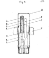
- Figur 1 einen Schnitt durch einen Meßkopf, bei dem die elektro-chemische Zelle aus einem Zirkonoxidröhrchen besteht, in dessen oberem Abschnitt die Bezugsmasse angeordnet ist,
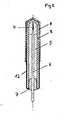
- Figur 2 ebenfalls im Schnitt eine andere Art der Umhüllung des Zirkonoxidröhrchens der auf Figur 1 dargestellten Ausführungsform und
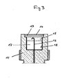
- Figur 3 einen senkrechten Schnitt durch den oberen Abschnitt eines Meßkopfes, bei dem die Zirkonoxidmasse die Form einer Scheibe hat.
- Der untere Teil des auf Figur 1 dargestellten Meßkopfes 1 enthält die Steckvorrichtung zum Anschluß an eine Meßlanze und ist in bekannter Weise ausgebildet. Mit 11 ist der Keramikkörper bezeichnet, der die eigentliche Meßzelle, sowie ein Thermoelement 9 aufnimmt. Die elektro-chemische Zelle 2 besteht aus einem Zirkonoxidröhrchen 3, in dessen oberem geschlossenem Abschnitt die Bezugsmasse 4 angeordnet ist. Der übrige Raum des Röhrchens ist mit einer Füllmasse 5, vorzugsweise aus Aluminiumoxid (A1203) ausgefüllt. Durch diese erstreckt sich ein bis zu der Steckvorrichtung geführter Leiter 6, z.B. ein Molybdändraht, der innerhalb der Bezugsmasse 4 endet. Das Zirkonoxidröhrchen 3 ist mit einem dicht an diesem anliegenden Schutzschirm 8 umgeben, der aus einem Metall besteht, das beim Eintauchen in die Metallschmelze schmilzt. Der Schutzschirm ragt an seinem unten offenen Ende ein Stück über das Zirkonoxidröhrchen hinaus und ist mit einem Verschluß 7 versehen, durch den der Leiter 6 dicht hindurchgeführt ist und der das untere Ende des Zirkonoxidröhrchens 3 dicht abschließt. Bei der auf der Zeichnung dargestellten Ausführungsform ragt der Verschluß 7 mit einem verjüngten Abschnitt ein Stück in das Zirkonoxidröhrchen hinein, während der Abschnitt mit dem größeren Durchmesser dicht an der Innenwandung des Schutzschirmes anliegt. Mit 10 ist eine Schutzkappe bezeichnet, die üblicherweise bei derartigen Meßvorrichtungen benutzt wird und die beispielsweise aus Pappe oder aber auch aus Metall bestehen kann.
- Die Umhüllung des Zirkonoxidröhrchens kann auch in der auf Figur 2 dargestellten Weise erfolgen, bei der für sich entsprechende Teile die gleichen Bezugszeichen gewählt wurden wie bei der vorstehend erläuterten Figur 1. Bei der zweiten Ausführungsform ist das Zirkonoxidröhrchen 3 ebenfalls mit einem dicht an diesem anliegenden Schutzschirm 8 umgeben, der sich jedoch nicht bis zu dem unten offenen Ende des Zirkonoxidröhrchens erstreckt, sondern nur über beispielsweise 2/3 der Länge. Der untere Abschnitt des Röhrchens ist mit einer das Eindringen von Feuchtigkeit verhindernden Umhüllung 12, z.B.aus Kunststoff, umgeben, die ein Stück unter das offene Ende des Schutzschirmes geführt ist, um eine einwandfreie Abdichtung zu erzielen und am unteren Ende des Zirkonoxidröhrchens an den Verschluß 7 anschließt.
- Auf Figur 3 ist die Ausführungsform dargestellt, bei der die Zirkonoxidmasse die Form einer Scheibe 13 hat, die in einer vorderen Ausnehmung 17 des Keramikkörpers 11 angeordnet ist. Der ebenfalls scheibenförmig ausgebildete Schutzschirm 14 liegt dabei auf der oberen Fläche der Scheibe 13 aus Zirkonoxid auf und ist mit einem geeigneten Verbindungsmittel, vorzugsweise feuerfestem Zement oder Kitt, an dem Keramikteil 11 befestigt. In der vorderen Ausnehmung dieses Keramikteils befindet sich ferner die Bezugsmasse 15, in der der Leiter 16 endet. Die gesamte vordere Ausnehmung 17 des aus der Keramikmasse bestehenden Teils des Meßkopfes ist mit einer Umhüllung oder Beschichtung 18 versehen, die die aus der Zirkonoxidmasse und der Bezugsmasse bestehende elektro-chemische Zelle vollständig umgibt und .das Eindringen von Feuchtigkeit verhindert.
Claims (8)
Priority Applications (1)
| Application Number | Priority Date | Filing Date | Title |
|---|---|---|---|
| AT81104035T ATE12312T1 (de) | 1980-06-12 | 1981-05-26 | Vorrichtung zur bestimmung des aktiven sauerstoffgehaltes von metallschmelzen. |
Applications Claiming Priority (2)
| Application Number | Priority Date | Filing Date | Title |
|---|---|---|---|
| DE3021949A DE3021949C2 (de) | 1980-06-12 | 1980-06-12 | Vorrichtung zur Bestimmung des aktiven Sauerstoffgehaltes von Metallschmelzen |
| DE3021949 | 1980-06-12 |
Publications (3)
| Publication Number | Publication Date |
|---|---|
| EP0042086A2 true EP0042086A2 (de) | 1981-12-23 |
| EP0042086A3 EP0042086A3 (en) | 1982-02-24 |
| EP0042086B1 EP0042086B1 (de) | 1985-03-20 |
Family
ID=6104380
Family Applications (1)
| Application Number | Title | Priority Date | Filing Date |
|---|---|---|---|
| EP81104035A Expired EP0042086B1 (de) | 1980-06-12 | 1981-05-26 | Vorrichtung zur Bestimmung des aktiven Sauerstoffgehaltes von Metallschmelzen |
Country Status (8)
| Country | Link |
|---|---|
| EP (1) | EP0042086B1 (de) |
| JP (1) | JPS5724852A (de) |
| AT (1) | ATE12312T1 (de) |
| AU (1) | AU544260B2 (de) |
| BR (1) | BR8103698A (de) |
| CA (1) | CA1173505A (de) |
| DE (1) | DE3021949C2 (de) |
| ZA (1) | ZA813561B (de) |
Cited By (4)
| Publication number | Priority date | Publication date | Assignee | Title |
|---|---|---|---|---|
| EP0189557A1 (de) * | 1984-12-19 | 1986-08-06 | Ferrotron Elektronik GmbH | Festelektrolyt-Tauchsonde |
| FR2820207A1 (fr) * | 2001-01-26 | 2002-08-02 | Heraeus Electro Nite Int | Dispositif de mesure pour determiner l'activite de l'oxygene dans des metaux en fusion ou dans du laitier en fusion |
| DE10255282B4 (de) * | 2002-11-26 | 2005-07-14 | Specialty Minerals Michigan Inc., Bingham Farms | Sonde zur Ermittlung der Sauerstoffaktivität von Metallschmelzen und Verfahren zu ihrer Herstellung |
| US9243936B2 (en) | 2012-03-16 | 2016-01-26 | Janesko Oy | Measuring sensor |
Families Citing this family (8)
| Publication number | Priority date | Publication date | Assignee | Title |
|---|---|---|---|---|
| JPS6281560A (ja) * | 1985-10-04 | 1987-04-15 | Tokyo Yogyo Co Ltd | 溶融金属用水素センサ− |
| JP3560260B2 (ja) | 1995-05-01 | 2004-09-02 | 富士写真フイルム株式会社 | 指紋像記録シート |
| DE102005019665B3 (de) * | 2005-04-26 | 2006-08-31 | Heraeus Electro-Nite International N.V. | Eintauchmesssonde, insbesondere Einwurfmesssonde |
| DE102005060492B3 (de) * | 2005-12-15 | 2007-05-24 | Heraeus Electro-Nite International N.V. | Messsonde zur Messung in Metall- oder Schlackeschmelzen |
| DE102007004147A1 (de) | 2007-01-22 | 2008-07-24 | Heraeus Electro-Nite International N.V. | Verfahren zum Beeinflussen der Eigenschaften von Gusseisen sowie Sauerstoffsensor |
| DE102012112872A1 (de) * | 2012-12-21 | 2014-07-10 | Conti Temic Microelectronic Gmbh | Sensoranordnung und Verfahren zur Herstellung einer Sensoranordnung |
| DE102013002389A1 (de) * | 2013-02-13 | 2014-08-14 | Minkon GmbH | Steckersystem, Messkopf, Kontaktstück, Verfahren zum Bestimmen einer Temperatur und einer elektromotorischen Kraft sowie Signalleitungsvorrichtung |
| EP4628885A1 (de) * | 2024-04-04 | 2025-10-08 | Heraeus Electro-Nite International N.V. | Vorrichtung zur messung des sauerstoffgehaltes in metallschmelzen |
Family Cites Families (5)
| Publication number | Priority date | Publication date | Assignee | Title |
|---|---|---|---|---|
| FR1493717A (fr) * | 1966-07-21 | 1967-09-01 | Meci Materiel Elect Contr | Sonde perfectionnée pour mesures dans des liquides à très haute température |
| FR2390727A1 (fr) * | 1977-05-11 | 1978-12-08 | Renault | Cellule de mesure permettant de determiner la concentration en oxygene dans un melange gazeux |
| DE2811066C3 (de) * | 1978-03-14 | 1981-01-08 | Nippondenso Co., Ltd., Kariya, Aichi (Japan) | Sauerstoff-Meßfühler |
| FR2422162A1 (fr) * | 1978-04-06 | 1979-11-02 | Electro Nite | Perfectionnements aux dispositifs de mesure de la teneur en oxygene actif de bains de metaux en fusion |
| DE7907878U1 (de) * | 1978-04-06 | 1979-07-12 | Electro-Nite, N.V., Houthalen (Belgien) | Vorrichtung zur Bestimmung des aktiven Sauerstoffgehaltes von Metallschmelzen |
-
1980
- 1980-06-12 DE DE3021949A patent/DE3021949C2/de not_active Expired
-
1981
- 1981-05-26 AT AT81104035T patent/ATE12312T1/de not_active IP Right Cessation
- 1981-05-26 EP EP81104035A patent/EP0042086B1/de not_active Expired
- 1981-05-27 ZA ZA00813561A patent/ZA813561B/xx unknown
- 1981-06-08 JP JP8701181A patent/JPS5724852A/ja active Pending
- 1981-06-11 CA CA000379544A patent/CA1173505A/en not_active Expired
- 1981-06-11 BR BR8103698A patent/BR8103698A/pt not_active IP Right Cessation
- 1981-06-12 AU AU71676/81A patent/AU544260B2/en not_active Ceased
Cited By (5)
| Publication number | Priority date | Publication date | Assignee | Title |
|---|---|---|---|---|
| EP0189557A1 (de) * | 1984-12-19 | 1986-08-06 | Ferrotron Elektronik GmbH | Festelektrolyt-Tauchsonde |
| FR2820207A1 (fr) * | 2001-01-26 | 2002-08-02 | Heraeus Electro Nite Int | Dispositif de mesure pour determiner l'activite de l'oxygene dans des metaux en fusion ou dans du laitier en fusion |
| DE10255282B4 (de) * | 2002-11-26 | 2005-07-14 | Specialty Minerals Michigan Inc., Bingham Farms | Sonde zur Ermittlung der Sauerstoffaktivität von Metallschmelzen und Verfahren zu ihrer Herstellung |
| US7578913B2 (en) | 2002-11-26 | 2009-08-25 | Specialty Minerals (Michigan) Inc. | Probe for determination of oxygen activity in metal melts and methods for its production |
| US9243936B2 (en) | 2012-03-16 | 2016-01-26 | Janesko Oy | Measuring sensor |
Also Published As
| Publication number | Publication date |
|---|---|
| ZA813561B (en) | 1982-06-30 |
| CA1173505A (en) | 1984-08-28 |
| AU544260B2 (en) | 1985-05-23 |
| BR8103698A (pt) | 1982-03-02 |
| ATE12312T1 (de) | 1985-04-15 |
| AU7167681A (en) | 1981-12-17 |
| DE3021949A1 (de) | 1981-12-17 |
| EP0042086A3 (en) | 1982-02-24 |
| DE3021949C2 (de) | 1982-09-02 |
| EP0042086B1 (de) | 1985-03-20 |
| JPS5724852A (en) | 1982-02-09 |
Similar Documents
| Publication | Publication Date | Title |
|---|---|---|
| EP0042086B1 (de) | Vorrichtung zur Bestimmung des aktiven Sauerstoffgehaltes von Metallschmelzen | |
| DE2930617B2 (de) | Schutzkappe für eine Probennadel | |
| DE1808584A1 (de) | Elektrochemische Zelle | |
| DE2327746A1 (de) | Geraet zum elektrochemischen messen der sauerstoffaktivitaet einer metallschmelze | |
| DE2910261A1 (de) | Entluefteter fuellzapfen fuer elektrische akkumulator-zellen | |
| DE2021318C3 (de) | Meßelektrode zur Messung von Ionen in Lösungen | |
| DE2555147A1 (de) | Wasserdichte dichtvorrichtung fuer eine elektrische stecker/buchsen-kupplung | |
| DE4007819C2 (de) | ||
| DE8910869U1 (de) | Vorrichtung zur Entnahme von Proben aus Metallschmelzen | |
| DE3804880C2 (de) | ||
| DE2819338C2 (de) | Vorrichtung zum Entnehmen von Proben aus geschmolzenem Metall für die Wasserstoffanalyse der Metallschmelze | |
| DE2703774C3 (de) | Primärtrockenrundzelle mit einem sich bei Überdruck öffnenden Gasventil | |
| DE29820910U1 (de) | Pipette mit Adaptereinsatz | |
| DE3811915A1 (de) | Messvorrichtung zum messen des sauerstoffpartialdruckes in aggressiven fluessigkeiten hoher temperatur | |
| DE3888499T2 (de) | Trockenzelle. | |
| DE3347046C2 (de) | Meßsonde zum Messen des elektrischen Potentials über dem Boden von Flüssigkeitsbehältern mit kathodischem Korrosionsschutz | |
| DE2808621C2 (de) | Sauerstoffmeßfühler | |
| DE7907878U1 (de) | Vorrichtung zur Bestimmung des aktiven Sauerstoffgehaltes von Metallschmelzen | |
| DE899213C (de) | Verfahren zur Erhoehung der Lagerfaehigkeit von Akkumulatoren und Verschluss fuer das Akkumulatorgehaeuse | |
| DE4222560A1 (de) | Verschlußstopfen | |
| DE2343613A1 (de) | Verfahren und einrichtung zum abdichten von kabeln | |
| DE8033391U1 (de) | Beschwerte sonde zur enteralen ernaehrung | |
| DE3433349A1 (de) | Vorrichtung zum einfuehren von gas in eine metallschmelze | |
| DE659743C (de) | Zuendkerze | |
| DE8707781U1 (de) | Vorrichtung zur Bestimmung des Kohlenstoffgehaltes und der Temperatur eines flüssigen Metalls |
Legal Events
| Date | Code | Title | Description |
|---|---|---|---|
| PUAI | Public reference made under article 153(3) epc to a published international application that has entered the european phase |
Free format text: ORIGINAL CODE: 0009012 |
|
| AK | Designated contracting states |
Designated state(s): AT BE CH FR GB IT LU NL SE |
|
| PUAL | Search report despatched |
Free format text: ORIGINAL CODE: 0009013 |
|
| AK | Designated contracting states |
Designated state(s): AT BE CH FR GB IT LU NL SE |
|
| 17P | Request for examination filed |
Effective date: 19820524 |
|
| ITF | It: translation for a ep patent filed | ||
| GRAA | (expected) grant |
Free format text: ORIGINAL CODE: 0009210 |
|
| AK | Designated contracting states |
Designated state(s): AT BE CH FR GB IT LI LU NL SE |
|
| REF | Corresponds to: |
Ref document number: 12312 Country of ref document: AT Date of ref document: 19850415 Kind code of ref document: T |
|
| ET | Fr: translation filed | ||
| PLBE | No opposition filed within time limit |
Free format text: ORIGINAL CODE: 0009261 |
|
| STAA | Information on the status of an ep patent application or granted ep patent |
Free format text: STATUS: NO OPPOSITION FILED WITHIN TIME LIMIT |
|
| 26N | No opposition filed | ||
| ITTA | It: last paid annual fee | ||
| PGFP | Annual fee paid to national office [announced via postgrant information from national office to epo] |
Ref country code: BE Payment date: 19940419 Year of fee payment: 14 |
|
| PGFP | Annual fee paid to national office [announced via postgrant information from national office to epo] |
Ref country code: FR Payment date: 19940420 Year of fee payment: 14 Ref country code: CH Payment date: 19940420 Year of fee payment: 14 |
|
| PGFP | Annual fee paid to national office [announced via postgrant information from national office to epo] |
Ref country code: GB Payment date: 19940421 Year of fee payment: 14 |
|
| PGFP | Annual fee paid to national office [announced via postgrant information from national office to epo] |
Ref country code: SE Payment date: 19940425 Year of fee payment: 14 |
|
| PGFP | Annual fee paid to national office [announced via postgrant information from national office to epo] |
Ref country code: AT Payment date: 19940426 Year of fee payment: 14 |
|
| PGFP | Annual fee paid to national office [announced via postgrant information from national office to epo] |
Ref country code: LU Payment date: 19940430 Year of fee payment: 14 |
|
| PGFP | Annual fee paid to national office [announced via postgrant information from national office to epo] |
Ref country code: NL Payment date: 19940531 Year of fee payment: 14 |
|
| EPTA | Lu: last paid annual fee | ||
| REG | Reference to a national code |
Ref country code: FR Ref legal event code: CD |
|
| EAL | Se: european patent in force in sweden |
Ref document number: 81104035.1 |
|
| PG25 | Lapsed in a contracting state [announced via postgrant information from national office to epo] |
Ref country code: LU Free format text: LAPSE BECAUSE OF NON-PAYMENT OF DUE FEES Effective date: 19950526 Ref country code: GB Effective date: 19950526 Ref country code: AT Effective date: 19950526 |
|
| PG25 | Lapsed in a contracting state [announced via postgrant information from national office to epo] |
Ref country code: SE Effective date: 19950527 |
|
| PG25 | Lapsed in a contracting state [announced via postgrant information from national office to epo] |
Ref country code: LI Effective date: 19950531 Ref country code: CH Effective date: 19950531 Ref country code: BE Effective date: 19950531 |
|
| BERE | Be: lapsed |
Owner name: ELECTRO-NITE N.V. Effective date: 19950531 |
|
| PG25 | Lapsed in a contracting state [announced via postgrant information from national office to epo] |
Ref country code: NL Effective date: 19951201 |
|
| GBPC | Gb: european patent ceased through non-payment of renewal fee |
Effective date: 19950526 |
|
| REG | Reference to a national code |
Ref country code: CH Ref legal event code: PL |
|
| NLV4 | Nl: lapsed or anulled due to non-payment of the annual fee |
Effective date: 19951201 |
|
| EUG | Se: european patent has lapsed |
Ref document number: 81104035.1 |
|
| PG25 | Lapsed in a contracting state [announced via postgrant information from national office to epo] |
Ref country code: FR Effective date: 19960229 |
|
| REG | Reference to a national code |
Ref country code: FR Ref legal event code: ST |
|
| REG | Reference to a national code |
Ref country code: FR Ref legal event code: ST |