EP0042304A1 - Kopiersteuersystem - Google Patents
Kopiersteuersystem Download PDFInfo
- Publication number
- EP0042304A1 EP0042304A1 EP81302713A EP81302713A EP0042304A1 EP 0042304 A1 EP0042304 A1 EP 0042304A1 EP 81302713 A EP81302713 A EP 81302713A EP 81302713 A EP81302713 A EP 81302713A EP 0042304 A1 EP0042304 A1 EP 0042304A1
- Authority
- EP
- European Patent Office
- Prior art keywords
- trace
- axis
- tracing
- difference
- tracer
- Prior art date
- Legal status (The legal status is an assumption and is not a legal conclusion. Google has not performed a legal analysis and makes no representation as to the accuracy of the status listed.)
- Granted
Links
- 239000000700 radioactive tracer Substances 0.000 title claims abstract description 20
- 238000006073 displacement reaction Methods 0.000 claims abstract description 13
- 101100321720 Arabidopsis thaliana PP2AA1 gene Proteins 0.000 description 4
- 238000001514 detection method Methods 0.000 description 4
- 238000010586 diagram Methods 0.000 description 3
- 238000013459 approach Methods 0.000 description 2
- 239000002131 composite material Substances 0.000 description 2
- KTAVBOYXMBQFGR-MAODNAKNSA-J tetrasodium;(6r,7r)-7-[[(2z)-2-(2-amino-1,3-thiazol-4-yl)-2-methoxyimino-1-oxidoethylidene]amino]-3-[(2-methyl-5,6-dioxo-1h-1,2,4-triazin-3-yl)sulfanylmethyl]-8-oxo-5-thia-1-azabicyclo[4.2.0]oct-2-ene-2-carboxylate;heptahydrate Chemical compound O.O.O.O.O.O.O.[Na+].[Na+].[Na+].[Na+].S([C@@H]1[C@@H](C(N1C=1C([O-])=O)=O)NC(=O)\C(=N/OC)C=2N=C(N)SC=2)CC=1CSC1=NC(=O)C([O-])=NN1C.S([C@@H]1[C@@H](C(N1C=1C([O-])=O)=O)NC(=O)\C(=N/OC)C=2N=C(N)SC=2)CC=1CSC1=NC(=O)C([O-])=NN1C KTAVBOYXMBQFGR-MAODNAKNSA-J 0.000 description 2
- 241001422033 Thestylus Species 0.000 description 1
- 238000006243 chemical reaction Methods 0.000 description 1
- 238000012986 modification Methods 0.000 description 1
- 230000004048 modification Effects 0.000 description 1
- 230000002441 reversible effect Effects 0.000 description 1
- 238000005070 sampling Methods 0.000 description 1
Images

Classifications
-
- B—PERFORMING OPERATIONS; TRANSPORTING
- B23—MACHINE TOOLS; METAL-WORKING NOT OTHERWISE PROVIDED FOR
- B23Q—DETAILS, COMPONENTS, OR ACCESSORIES FOR MACHINE TOOLS, e.g. ARRANGEMENTS FOR COPYING OR CONTROLLING; MACHINE TOOLS IN GENERAL CHARACTERISED BY THE CONSTRUCTION OF PARTICULAR DETAILS OR COMPONENTS; COMBINATIONS OR ASSOCIATIONS OF METAL-WORKING MACHINES, NOT DIRECTED TO A PARTICULAR RESULT
- B23Q35/00—Control systems or devices for copying directly from a pattern or a master model; Devices for use in copying manually
- B23Q35/04—Control systems or devices for copying directly from a pattern or a master model; Devices for use in copying manually using a feeler or the like travelling along the outline of the pattern, model or drawing; Feelers, patterns, or models therefor
- B23Q35/08—Means for transforming movement of the feeler or the like into feed movement of tool or work
- B23Q35/12—Means for transforming movement of the feeler or the like into feed movement of tool or work involving electrical means
- B23Q35/121—Means for transforming movement of the feeler or the like into feed movement of tool or work involving electrical means using mechanical sensing
- B23Q35/123—Means for transforming movement of the feeler or the like into feed movement of tool or work involving electrical means using mechanical sensing the feeler varying the impedance in a circuit
Definitions
- the present invention relates to a tracer control system.
- a preferred embodiment of the invention is designed to provide accurate control tracing in an arbitrary direction. Description of the Prior Art;
- a tracer control system which is adapted and arranged such that, with a tracing machine, the magnitude and direction of displacement of a tracer head tracing the surface of a model are determined from displacement signals from the tracer head, and trace control velocities are calculated so that the magnitude of the displacement may become constant, thereby to provide tracing in a set trace direction in an X-Y plane, said system comprising:
- the actual trace direction can be made substantially identical with the set trace direction since the actual trace direction is corrected for each unit distance x 0 .
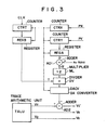
- Fig. 3 illustrates in block form the principal part of an embodiment of the present invention.
- Position detection pulses PX in the X axis are counted by a counter CTRX and position detection pulses PY in the Y axis are counted by a counter CTRY.
- the counter CTRX has such a count capacity that overflows by counting the position detection pulses PX corresponding in number to the aforementioned unit distance x 0 and this overflow signal is used as a reset signal for each of the counters CTRY and CTRT, a set signal for each of registers REGA and REGB and a sampling signal for a D-A converter DACV.
- the counter CTRT counts clock pulses CLK and its count content is set by the overflow signal in the register REGB and then reset. Similarly the count content of the counter CTRY is also set by the overflow signal in the register REGA, thereafter being reset.
- the content of the register REGB indicates the time t for the movement at the unit distance x 0 in the.X-axis direction and the content of the register REGA indicates the distance in the Y-axis direction by the movement at the unit distance x 0 . Since the angle a of the trace direction to the X axis and the unit distance x 0 are predetermined, the distance of movement in the Y-axis direction after the movement at the unit distance x 0 in the X-axis direction is x 0 ⁇ tan a. Then, by obtaining the difference between the content of the register REGA and x 0 ⁇ tan a in an adder AD 1, the deviation ⁇ y from the predetermined position can be detected.
- the deviation ⁇ y is doubled by a multiplier ML, the output from which is applied to a divider DV, wherein a division is effected using the content of the register REGB as the denominator.
- a multiplier ML In the case of a binary digital signal, it is doubled by a one-bit shift, so that the multiplier ML can be formed by a simple shift circuit.
- the output from the divider DV is provided to the D-A converter DACV for conversion into an analog signal, which is applied to an adder AD2, wherein it is added to the Y-axis trace velocity signal Vy from a trace arithmetic unit TALU.
- the trace velocity signal V Y ' subjected to the angle correction in accordance with expression (1) or (2) is yielded.
- the trace velocity signal V Y ' thus obtained and the velocity signals V x and V z in the X and Z axes are applied to motor drive circuits of the respective axes, performing a trace in the direction having the angle a relative to the X axis.
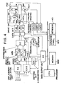
- FIG. 4 illustrates in block form a tracer control equipment provided with a processor.
- a tracing machine MAC is equipped with a motor MZ for moving in the Z-axis direction a tracer head TR having a stylus ST for contact with a model MDL and a cutter CT for cutting a work W, motors MX and MY for moving the model MDL and the work W in the X-Y plane, and position detectors PCX, PCY and PCZ for position detection, such as resolvers, pulse coders or the like.
- a displacement calculation circuit DG conducts a calculation using displacement signals ⁇ x , ⁇ y and ⁇ z from the tracer head TR to provide a composite displacement signal .
- a switching circuit CHG responds to a command signal to apply two of the displacement signals ⁇ x , ⁇ y and ⁇ z to an indexing circuit ID. Pulses from the position detectors PCX, PCY and PCZ are respectively applied to reversible counters CNTX, CNTY and CNTZ, wherein they are counted up or down depending on the direction of movement of the tracing machine, and the count contents of the counters each indicate the current position of the stylus ST in each axis.
- a memory MEM has prestored therein a control program and various data. For example, from a keyboard KB are entered data such as a trace direction, a trace velocity, a nominal deflection, an approach velocity, a pick feed velocity and they are stored under control of a processor CPU. An operator panel OPP has velocity setting dials, a start button and so forth. Data from the processor CPU to the respective parts are provided via a data output unit DO.
- the nominal deflection stored in the memory MEM is read out therefrom under control of the processor CPU and applied via the data output unit DO to a D-A converter DA1, from which an analog nominal deflection signal ⁇ 0 is provided to an adder ADD to obtain the difference between the nominal deflection signal and the composite displacement signal e.
- the resulting difference signal ⁇ is applied to velocity control circuits ARN and ART to provide therefrom a normal-direction velocity signal V N and a tangential-direction velocity signal V T to a distribution circuit DC.
- the indexing circuit ID applies to the distribution circuit DC displacement direction signals sin 8 and cos ⁇ coordinate-transformed in accordance with a trace direction signal.
- the distribution circuit DC yields a velocity signal Va in the trace axis Aa and a velocity signal V z in the X axis.
- the velocity signal Va is converted by a gate circuit GC into X-axis and Y-axis velocity signals in accordance with the trace direction signal.
- the velocity signals in the respective axes are provided to drive circuits AX, AY and AZ to drive the motors MX, MY and MZ in the respective axes, performing tracing in the direction of the axis Aa.
- the movement at the unit distance x 0 in the X-axis direction is judged by the processor CPU by reading out the content of the counter CNTX.
- the previous content of the counter CNTX is stored in the memory MEM and it is judged whether the difference between the stored content and the current content of the counter CNTX is the unit distance x 0 or not.
- the time t for the movement at the unit distance x 0 can easily be discerned by counting clock pulses in the processor CPU.
- the content of the counter CNTY is read out therefrom and compared with the previous content of the counter CNTY stored in the memory, by which it is possible to obtain the distance actually moved in the Y-axis direction by the movement at the unit distance x 0 .
- the angle a to the X axis and the unit distance x 0 are predetermined and x 0 ⁇ tan a is calculated and prestored in the memory MEM, so that the deviation A can be obtained, by which the second term of expression (1) or (2) is calculated.
- the resulting angle correction signal is applied from the processor CPU to a D-A converter DA 2 via the data output unit DO and provided as an analog angle correction signal to the gate circuit GC to correct the Y-axis velocity signal. This ensures accurate tracing in the set trace direction.
- the difference between the set trace direction and the actual trace direction detected by the position detectors is obtained for each constant distance of movement in the X or Y axis and the trace velocity in the X or Y axis is corrected so that the abovesaid .difference may be reduced to zero.
- the angle correcting means can be achieved by such an arrangement as shown in Fig. 3 or 4 which conducts the calculation of expression (1) or (2). Since tracing is always performed in the set trace direction, the tracing accuracy can be enhanced. Furthermore, since tracing can be effected in an arbitrary direction in the X-Y plane, it is possible to select an optimum trace direction in accordance with the configuration of the model MDL.
Landscapes
- Engineering & Computer Science (AREA)
- Automation & Control Theory (AREA)
- Mechanical Engineering (AREA)
- Numerical Control (AREA)
- Machine Tool Copy Controls (AREA)
- Automatic Control Of Machine Tools (AREA)
- Control Of Position Or Direction (AREA)
Applications Claiming Priority (2)
| Application Number | Priority Date | Filing Date | Title |
|---|---|---|---|
| JP55082567A JPS6028624B2 (ja) | 1980-06-18 | 1980-06-18 | 倣い制御装置 |
| JP82567/80 | 1980-06-18 |
Publications (2)
| Publication Number | Publication Date |
|---|---|
| EP0042304A1 true EP0042304A1 (de) | 1981-12-23 |
| EP0042304B1 EP0042304B1 (de) | 1984-09-12 |
Family
ID=13778060
Family Applications (1)
| Application Number | Title | Priority Date | Filing Date |
|---|---|---|---|
| EP81302713A Expired EP0042304B1 (de) | 1980-06-18 | 1981-06-17 | Kopiersteuersystem |
Country Status (5)
| Country | Link |
|---|---|
| US (1) | US4424570A (de) |
| EP (1) | EP0042304B1 (de) |
| JP (1) | JPS6028624B2 (de) |
| KR (1) | KR840000862B1 (de) |
| DE (1) | DE3165999D1 (de) |
Cited By (4)
| Publication number | Priority date | Publication date | Assignee | Title |
|---|---|---|---|---|
| EP0097435A3 (en) * | 1982-05-28 | 1985-05-22 | Fanuc Ltd | Sampling control method and apparatus |
| EP0139011A4 (de) * | 1983-03-04 | 1987-06-17 | Fanuc Ltd | Vorrichtung zur kontrolle des profils. |
| EP0190357A4 (de) * | 1984-07-27 | 1989-03-16 | Fanuc Ltd | Steuerungsvorrichtung der multidirektionellen profilierung. |
| EP0412163A4 (en) * | 1988-07-08 | 1991-05-08 | Fanuc Ltd. | Digitizing method |
Families Citing this family (15)
| Publication number | Priority date | Publication date | Assignee | Title |
|---|---|---|---|---|
| JPS59209741A (ja) * | 1983-05-16 | 1984-11-28 | Fanuc Ltd | 任意方向倣い制御方式 |
| JPS6031954U (ja) * | 1983-08-11 | 1985-03-04 | フアナツク株式会社 | 倣い制御装置におけるシ−ケンス切換器 |
| JPS6099549A (ja) * | 1983-11-02 | 1985-06-03 | Fanuc Ltd | 任意方向ならい方法 |
| US4608658A (en) * | 1984-04-13 | 1986-08-26 | Pencept, Inc. | Method and apparatus for removing noise at the ends of a stroke caused by retracing |
| GB8626734D0 (en) * | 1986-11-08 | 1986-12-10 | Renishaw Plc | Coordinate positioning apparatus |
| JPH0729257B2 (ja) * | 1987-07-31 | 1995-04-05 | ファナック株式会社 | デジタイジング装置 |
| JPH01109057A (ja) * | 1987-10-23 | 1989-04-26 | Fanuc Ltd | デジタイジング方法 |
| US4848137A (en) * | 1988-03-23 | 1989-07-18 | The Boeing Company | Automated shim manufacturing system |
| JPH02145908A (ja) * | 1988-11-28 | 1990-06-05 | Okuma Mach Works Ltd | デジタイジング装置におけるスタイラスのたわみ補正自動設定方法 |
| JPH0386447A (ja) * | 1989-08-25 | 1991-04-11 | Fanuc Ltd | ならい制御装置 |
| JP3041039B2 (ja) * | 1990-05-11 | 2000-05-15 | フット イメージ テクノロジー,インコーポレイテッド | 足測定、靴型及び履き物製造の統合システム |
| US5195030A (en) * | 1990-05-11 | 1993-03-16 | Foot Image Technology, Inc. | System and method of foot shape imaging and overlay |
| US5128880A (en) * | 1990-05-11 | 1992-07-07 | Foot Image Technology, Inc. | Foot measurement and footwear sizing system |
| US5237520A (en) * | 1990-05-11 | 1993-08-17 | Foot Image Technology, Inc. | Foot measurement and footwear sizing system |
| US5206804A (en) * | 1990-05-11 | 1993-04-27 | Foot Image Technology, Inc. | Footwear visual image cataloging and sizing |
Citations (2)
| Publication number | Priority date | Publication date | Assignee | Title |
|---|---|---|---|---|
| US412023A (en) * | 1889-10-01 | Thomas | ||
| GB2017344A (en) * | 1978-03-23 | 1979-10-03 | Fujitsu Fanuc Ltd | Tracer apparatus |
Family Cites Families (7)
| Publication number | Priority date | Publication date | Assignee | Title |
|---|---|---|---|---|
| US3624343A (en) | 1970-01-26 | 1971-11-30 | Smith Corp A O | Member drive system with constant velocity in a given plane |
| US3707662A (en) | 1970-08-03 | 1972-12-26 | Gettys Mfg Co Inc | Machine tool velocity control system |
| US3764877A (en) | 1971-12-23 | 1973-10-09 | Koehring Co | Structure for and method of pattern tracing control |
| US4064446A (en) | 1973-01-18 | 1977-12-20 | Indramat-Gesellschaft Fur Industrie-Rationalisierung Und Automatisierung | Duplicating method and arrangement |
| CH596949A5 (de) | 1975-09-30 | 1978-03-31 | Siemens Ag | |
| US4117385A (en) | 1977-01-26 | 1978-09-26 | Automation Equipment Inc. | Tracer control circuit |
| US4325013A (en) | 1980-03-28 | 1982-04-13 | Wenzel Robert H | Electrical tracer control system utilizing sine wave resolution |
-
1980
- 1980-06-18 JP JP55082567A patent/JPS6028624B2/ja not_active Expired
-
1981
- 1981-06-10 US US06/272,200 patent/US4424570A/en not_active Expired - Fee Related
- 1981-06-12 KR KR1019810002130A patent/KR840000862B1/ko not_active Expired
- 1981-06-17 EP EP81302713A patent/EP0042304B1/de not_active Expired
- 1981-06-17 DE DE8181302713T patent/DE3165999D1/de not_active Expired
Patent Citations (2)
| Publication number | Priority date | Publication date | Assignee | Title |
|---|---|---|---|---|
| US412023A (en) * | 1889-10-01 | Thomas | ||
| GB2017344A (en) * | 1978-03-23 | 1979-10-03 | Fujitsu Fanuc Ltd | Tracer apparatus |
Cited By (4)
| Publication number | Priority date | Publication date | Assignee | Title |
|---|---|---|---|---|
| EP0097435A3 (en) * | 1982-05-28 | 1985-05-22 | Fanuc Ltd | Sampling control method and apparatus |
| EP0139011A4 (de) * | 1983-03-04 | 1987-06-17 | Fanuc Ltd | Vorrichtung zur kontrolle des profils. |
| EP0190357A4 (de) * | 1984-07-27 | 1989-03-16 | Fanuc Ltd | Steuerungsvorrichtung der multidirektionellen profilierung. |
| EP0412163A4 (en) * | 1988-07-08 | 1991-05-08 | Fanuc Ltd. | Digitizing method |
Also Published As
| Publication number | Publication date |
|---|---|
| JPS6028624B2 (ja) | 1985-07-05 |
| US4424570A (en) | 1984-01-03 |
| DE3165999D1 (en) | 1984-10-18 |
| KR840000862B1 (ko) | 1984-06-20 |
| JPS578056A (en) | 1982-01-16 |
| EP0042304B1 (de) | 1984-09-12 |
| KR830005969A (ko) | 1983-09-14 |
Similar Documents
| Publication | Publication Date | Title |
|---|---|---|
| EP0042304B1 (de) | Kopiersteuersystem | |
| US4224670A (en) | Tracer control system | |
| US4628609A (en) | Incremental measuring and machine control system | |
| US4439825A (en) | Position regulation system containing a digital incremental measuring apparatus | |
| US4085890A (en) | Position detecting system | |
| EP0034006B1 (de) | Kopierverfahren | |
| EP0026630A1 (de) | Steuerungssystem für Kopier-Werkzeugmaschine | |
| US5202842A (en) | Rotational position detecting device which compensates for eccentricity of rotating object | |
| EP0242869B1 (de) | Numerische Steuerungseinrichtung | |
| EP0029294A1 (de) | Kopiersteuerungsvorrichtung | |
| US2892948A (en) | Positional control system for photoscanner | |
| US3728607A (en) | Phase analog numerical control system employing a laser digitized position feedback | |
| EP0215127B1 (de) | Vorrichtung zum nachweis der maschinenpositionen | |
| US4468666A (en) | Apparatus for determining a reference position of a moving member | |
| US4689539A (en) | Speed detecting device | |
| US5119004A (en) | Reference-point return method | |
| JPS5775310A (en) | Detector for positional error of numerical control machine tool | |
| US2945956A (en) | Course plotter | |
| US4654570A (en) | Upward tracing system | |
| EP0386251A1 (de) | Profil-steuerungsverfahren | |
| EP0081589A1 (de) | Numerische steuereinheit | |
| US3418548A (en) | Contour tracing and tracking system | |
| JP2597977B2 (ja) | 位置検出回路の基準点セツト方法 | |
| GB1586871A (en) | Infrared deviation measuring device | |
| JPS6225324Y2 (de) |
Legal Events
| Date | Code | Title | Description |
|---|---|---|---|
| PUAI | Public reference made under article 153(3) epc to a published international application that has entered the european phase |
Free format text: ORIGINAL CODE: 0009012 |
|
| AK | Designated contracting states |
Designated state(s): DE FR GB |
|
| RBV | Designated contracting states (corrected) |
Designated state(s): DE FR GB |
|
| 17P | Request for examination filed |
Effective date: 19820604 |
|
| RAP1 | Party data changed (applicant data changed or rights of an application transferred) |
Owner name: FANUC LIMITED |
|
| GRAA | (expected) grant |
Free format text: ORIGINAL CODE: 0009210 |
|
| AK | Designated contracting states |
Designated state(s): DE FR GB |
|
| REF | Corresponds to: |
Ref document number: 3165999 Country of ref document: DE Date of ref document: 19841018 |
|
| ET | Fr: translation filed | ||
| PLBE | No opposition filed within time limit |
Free format text: ORIGINAL CODE: 0009261 |
|
| STAA | Information on the status of an ep patent application or granted ep patent |
Free format text: STATUS: NO OPPOSITION FILED WITHIN TIME LIMIT |
|
| 26N | No opposition filed | ||
| PGFP | Annual fee paid to national office [announced via postgrant information from national office to epo] |
Ref country code: FR Payment date: 19910528 Year of fee payment: 11 |
|
| PGFP | Annual fee paid to national office [announced via postgrant information from national office to epo] |
Ref country code: GB Payment date: 19910604 Year of fee payment: 11 |
|
| PG25 | Lapsed in a contracting state [announced via postgrant information from national office to epo] |
Ref country code: GB Effective date: 19920617 |
|
| GBPC | Gb: european patent ceased through non-payment of renewal fee |
Effective date: 19920617 |
|
| PG25 | Lapsed in a contracting state [announced via postgrant information from national office to epo] |
Ref country code: FR Effective date: 19930226 |
|
| REG | Reference to a national code |
Ref country code: FR Ref legal event code: ST |
|
| PGFP | Annual fee paid to national office [announced via postgrant information from national office to epo] |
Ref country code: DE Payment date: 19930630 Year of fee payment: 13 |
|
| PG25 | Lapsed in a contracting state [announced via postgrant information from national office to epo] |
Ref country code: DE Effective date: 19950301 |