EP0042443B1 - Zusammenlegbarer oder zusammenklappbarer Schi - Google Patents
Zusammenlegbarer oder zusammenklappbarer Schi Download PDFInfo
- Publication number
- EP0042443B1 EP0042443B1 EP80103037A EP80103037A EP0042443B1 EP 0042443 B1 EP0042443 B1 EP 0042443B1 EP 80103037 A EP80103037 A EP 80103037A EP 80103037 A EP80103037 A EP 80103037A EP 0042443 B1 EP0042443 B1 EP 0042443B1
- Authority
- EP
- European Patent Office
- Prior art keywords
- ski
- tip
- rear part
- collapsible
- skis
- Prior art date
- Legal status (The legal status is an assumption and is not a legal conclusion. Google has not performed a legal analysis and makes no representation as to the accuracy of the status listed.)
- Expired
Links
Images
Classifications
-
- A—HUMAN NECESSITIES
- A63—SPORTS; GAMES; AMUSEMENTS
- A63C—SKATES; SKIS; ROLLER SKATES; DESIGN OR LAYOUT OF COURTS, RINKS OR THE LIKE
- A63C5/00—Skis or snowboards
- A63C5/02—Skis or snowboards collapsible; divided
Definitions
- the invention relates to a collapsible ski consisting of a ski tip and a rear ski part, the ski tip and rear ski part being articulated to one another by an articulation point, and a connecting piece which overlaps the articulation point when the skis are open and on the ski rear part and on the ski tip via detachable parts Fasteners is attached.
- Skis have long been known as mass winter sports items. They are available in lengths of up to approx.2.20 m. Due to their bulky length, the transport of skis is often cumbersome. They have to be transported, for example, on trains in a pastry car, by car on a roof stand specially provided for this purpose and attached to the car roof, and on buses in separate ski stands provided on the rear bumper.
- skis In order to facilitate transportation, skis have already been proposed which consist of two parts which are connected to one another in an articulated manner, one of which forms the tip of the ski and the other the rear part of the ski, so that the skis can be folded up conveniently and easily for transportation to a handy size and for the Use can be unfolded again. Due to the articulated connection of the two ski parts, they are held together even when folded.
- a problem with a foldable ski that has not yet been satisfactorily solved is that it has the same properties as a non-foldable ski, i.e. in particular, when the ski is open or ready to ski, a rigid connection between the tip of the ski and the rear of the ski must be ensured, which, on the one hand, can be easily produced after opening and, on the other hand, is capable of absorbing the considerable forces which occur, for example, when driving through troughs.
- This rigid connection cannot be established by the joint alone, but additional connection means are required for this.
- these connecting means through their design and attachment to the ski, are actually capable of absorbing the forces acting between the tip of the ski and the rear of the ski, and are also integrated as far as possible into the tip of the ski or the rear of the ski when the ski is open, so that the above, impairing the handling of the ready-to-ski ski and an additional source of danger in the event of falls are avoided as far as possible.
- a collapsible ski (DE-A-24 52 728) is known in which the ski tip and the rear part of the ski are articulated to one another by an articulation point which is formed by two U-shaped articulated levers, each of which is connected at one end by means of an articulated pin the ski tip and is articulated on the rear part of the ski by means of a further joint pin.
- a plate-shaped connecting piece is provided for the rigid connection of both ski parts when the ski is open, that is to say ready to drive, which is guided on the two ski parts so as to be displaceable in the longitudinal direction of the ski and can thus be pushed over the articulation point.
- the two ski parts on both sides of the joint are provided on their longitudinal edges and on the top of the ski with a dovetail-like groove, in which angled legs of the plate-like connecting piece engage.
- a locking device is also provided on the plate-like connecting element, with the aid of which this connecting element can be fixed in its position overlapping the joint.
- a collapsible ski (AT-B-112 686), in which the connecting piece connecting the ski tip and the rear part of the ski consists of a rectangular plate, which lies with its longitudinal extension in the direction of the ski axis and on one end face by means of a hinge on the Top of the ski tip is articulated.
- this plate-shaped connecting element is secured on the other end side only by means of a screw on the rear part of the ski. Large forces, especially with the screw, cannot be transmitted with certainty.
- a collapsible ski (CH-A-171 068), in which the connection between the ski tip and the rear part of the ski is to be made with the aid of a connecting fitting which essentially consists of two angle pieces and a tensioning bracket which interacts with a tensioning lever.
- This clamp is pivoted together with the clamping lever on an elbow so that the clamping bracket can be pivoted behind a catch on the other elbow when the ski is open, then the final connection between the ski tip and the rear part of the ski is made by pivoting the clamping lever into its clamping position.
- connection fitting used in these known collapsible skis is extremely unreliable, since it is not necessarily apparent to the user that a secure connection between the ski tip and the rear part of the ski is actually established after pivoting the tensioning lever. Rather, it can happen, for example, due to carelessness or snow or ice residues that the tensioning lever is only insufficiently pivoted when connecting the ski tip and rear of the ski, so that the connection is then released while driving.
- the invention has for its object to show a collapsible ski of the type described, the connector ensures a safe and reliable force transmitting connection between the ski tip and the ski rear part with relatively simple design of this connector and the ski tip and the ski rear in the area of the joint , the connector being integrated into these two ski parts to the extent that protruding parts are largely avoided when the ski is open or ready to drive.
- a collapsible ski of the type described at the outset is designed according to the invention in such a way that the connecting piece can be inserted from above into a recess delimited by support surfaces in the rear part of the ski and in the ski tip and abuts against these support surfaces at both ends.
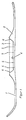
- FIG. 1 shows a side view of a ski in the opened or ready-to-run state. It essentially consists of a ski tip 1 and a ski rear part 2, which are articulated to one another by an articulation point 4.
- a connecting piece 3 is inserted from above into the ski formed by the ski tip 1 and the rear part 2 of the ski and bears on both ends against supporting surfaces 6 which, in connection with connecting elements 5, stabilize the ski, i.e. rigidly connect the ski tip 1 and the rear part 2 of the ski. The ski is then ready for use.
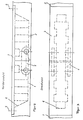
- Figures 2 and 3 show the front view and the top view of a second embodiment of the ski according to the invention and have the reference numerals used in Figure 1 for corresponding parts.
Landscapes
- Fittings On The Vehicle Exterior For Carrying Loads, And Devices For Holding Or Mounting Articles (AREA)
- Air Bags (AREA)
- Prostheses (AREA)
- Absorbent Articles And Supports Therefor (AREA)
- Footwear And Its Accessory, Manufacturing Method And Apparatuses (AREA)
Description
- Die Erfindung bezieht sich auf einen zusammenklappbaren Ski bestehend aus einer Skispitze und aus einem Skihinterteil, wobei Skispitze und Skihinterteil durch eine Gelenkstelle gelenkig miteinander verbunden sind, sowie aus einem Verbindungsstück, welches bei aufgeklappten Ski die Gelenkstelle überlappt und am Skihinterteil sowie an der Skispitze über lösbare Verbindungselemente befestigt ist.
- Skier sind als Massenwintersportartikel seit langem bekannt. Es gibt sie in Längen bis ca. 2,20 m. Ihrer sperrigen Länge wegen ist der Transport von Skiern oftmals umständlich. Sie müssen beispielsweise in Zügen im Gebäckwagen, mit dem Auto auf einem eigens dafür vorgesehenen und auf den Autodach befestigten Dachständer und bei Bussen in gesonderten, auf der hinteren Stoßstange vorgesehenen Skiständern transportiert werden.
- Insbesondere der Transport von Skiern auf Dachständern hat erhebliche Nachteile, da hierdurch der Luftwiderstand (c-Wert) des betreffenden Fahrzeuges erhöht wird und dieses Fahrzeug dann auch eine erhöhte Seitenwindempfindlichkeit aufweist. Schließlich lassen sich beim Transport von Skiern auf Dachständern folgenschwere Unfälle nicht ausschließen, da sich die Skier aus ihren Halterungen lösen und auf nachfolgende Fahrzeuge fallen können.
- Um den Transport zu erleichtern, wurden bereits Skier vorgeschlagen, die aus zwei gelenkig miteinander verbundenen Teilen bestehen, von denen eines die Skispitze und das andere das Skihinterteil bilden, so daß die Skier bequem und einfach für den Transport auf eine handliche Größe zusammengeklappt und für die Benutzung wieder auseinandergeklappt werden können. Durch die gelenkige Verbindung der beiden Skiteile sind diese auch im zusammengeklappten Zustand aneinander gehalten.
- Ein bisher noch nicht zufriedenstellend gelöstes Problem bei einem zusammenklappbaren Ski besteht darin, daß dieser die gleichen Eigenschaften aufweist wie ein nicht zusammenklappbarer Ski, d.h. insbesondere muß bei aufgeklapptem bzw. fahrbereitem Ski eine starre Verbindung zwischen der Skispitze und dem Skihinterteil ewährleistet sein, die einerseits nach dem Aufklappen einfach hergestellt werden kann und andererseits in der Lage ist, die beispielsweise beim Durchfahren von Mulden auftretenden erheblichen Kräfte aufzunehmen. Diese starre Verbindung kann durch die Gelenkstelle allein nicht hergestellt werden, sondern hierfür sind zusätzliche Verbindungsmittel erforderlich. Es ist daher auch zu fordern, daß diese Verbindungsmittel durch ihre Ausbildung und Anbringung am Ski tatsächlich in der Lage sind, die zwischen Skispitze und Skihinterteil wirkenden Kräfte aufzunehmen, und außerdem bei aufgeklapptem Ski möglichst weitgehend in die Skispitze bzw. in den Skihinterteil integriert sind, so daß vorstehende, die Handhabung des fahrbereiten Skis beeinträchtigende sowie eine zusätzliche Gefahrenquelle bei ev. Stürzen bedingende Teile soweit, wie möglich, vermieden werden.
- Bekannt ist ein zusammenklappbarer Ski (DE-A-24 52 728), bei dem die Skispitze und das Skihinterteil durch eine Gelenkstelle gelenkig miteinander verbunden sind, die von zwei U-förmigen Gelenkhebeln gebildet ist, von denen jeder an einem Ende mittels eines Gelenkstiftes an der Skispitze und mittels eines weiteren Gelenkstiftes am Skihinterteil angelenkt ist. Für die starre Verbindung beider Skiteile bei aufgeklapptem, also fahrbereitem Ski ist ein plattenförmiges Verbindungsstück vorgesehen, welches an den beiden Skiteilen in Skilängsrichtung verschiebbar geführt ist und somit über die Gelenkstelle geschoben werden kann. Hierfür sind die beiden Skiteile beiderseits der Gelenkstelle an ihren Längskanten und an der Skioberseite mit einer schwalbenschwanzartigen Nut versehen, in welche abgewinkelte Schenkel des plattenartigen Verbindungsstücks eingreifen. Am plattenartigen Verbindungselement ist weiterhin eine Aretierung vorgesehen, mit deren Hilfe dieses Verbindungselement in seiner die Gelenkstelle überlappenden Stellung festgelegt werden kann. Die insbesondere beim Durchfahren von Mulden zwischen der Skispitze und dem Skihinterteil auftretenden erheblichen Kräfte müssen bei diesem bekannten zusammenklappbaren Ski ausschließlich über die Schwalbenschwanz-Verbindungen von dem Verbindungsstück auf die Skispitze bzw. das Skihinterteil übertragen werden, mit der Folge, daß hier im hohen Maße die Gefahr besteht, daß das Material der Skiteile an den Nuten leicht ausbricht, und zwar insbesondere dann, wenn Skispitze und Skihinterteil aus Holz oder Kunststoff gefertigt sind.
- Bekannt ist weiterhin ein zusammenklappbarer Ski (AT-B-112 686), bei dem das die Skispitze und das Skihinterteil miteinander verbindende Verbindungsstück aus einer rechteckförmigen Platte besteht, die mit ihrer Längserstreckung in Richtung der Skiachse liegt und an einer Stirnseite mittels eines Scharniers an der Oberseite der Skispitze angelenkt ist. Bei aufgeklapptem Ski ist dieses plattenförmige Verbindungselement an der anderen Stirnseite lediglich mit Hilfe einer Schraube am Skihinterteil gesichert. Große Kräfte können vor allem durch die Schraube mit Sicherheit nicht übertragen werden. Es besteht hierbei vielmehr die Gefahr, daß wegen einer fehlenden, Druckkräfte aufnehmenden weiteren Abstützfläche sich die Schraube lockert und damit die starre Verbindung verloren geht bzw. das Gewinde der quer zu ihrer Achse beanspruchten Schraube sowie das Gegengewinde im Skihinterteil bei längerem Gebrauch des Skis deformiert werden, so daß ein Lösen und/oder Befestigen der Schraube schließlich nicht mehr möglich ist.
- Bekannt ist weiterhin ein zusammenklappbarer Ski (CH-A-171 068), bei dem die Verbindung zwischen der Skispitze und dem Skihinterteil mit Hilfe eines Verbindungsbeschlages erfolgen soll, der im wesentlichen aus zwei Winkelstücken sowie aus einem mit einem Spannhebel zusammenwirkenden Spannbügel besteht. Dieser Spannbügel ist zusammen mit dem Spannhebel an einem Winkelstück derart schwenkbar befestigt, daß der Spannbügel bei aufgeklapptem Ski hinter eine Fangrast am anderen Winkelstück geschwenkt werden kann, wobei dann durch Schwenken des Spannhebels in seine Spannstellung die endgültige Verbindung zwischen Skispitze und Skihinterteil hergestellt wird. Die beiden Winkelstücke des Verbindungsbeschlages sind dabei mit Schrauben so an der Oberseite der Skispitze bzw. des Skihinterteils im Bereich der Gelenkstelle befestigt, daß die Winkelstücke bei gespanntem Spannbügel und Spannhebel mit ihren über die Oberseite des Skis vorstehenden Winkelflächen flach gegeneinander anliegen. Der bei diesen bekannten zusammenklappbaren Ski verwendete Verbindungsbeschlag ist äußerst unzuverlässig, da für den Benutzer nicht unbedingt ersichtlich ist, daß nach dem Schwenken des Spannhebels eine sichere Verbindung zwischen Skispitze und Skihinterteil auch tatsächlich hergestellt ist. Vielmehr kann es beispielsweise aus Unachtsamkeit oder durch Schnee- oder Eisreste dazu kommen, daß der Spannhebel beim Verbinden von Skispitze und Skihinterteil nur ungenügend geschwenkt wird, so daß sich die Verbindung dann während des Fahrens löst. Hierbei kann es dann zu folgenschwerden Stürzen kommen, Nachteilig ist bei diesem bekannten Ski auch, daß die Winkelstücke des Verbindungsbeschlages weit über die Oberseite des Skis vorstehen, so daß sie beispielsweise bei Stürzen eine zusätzliche Gefahrenquelle bilden. Auch die Befestigung der Winkelstücke an der Skispitze bzw. am Skihinterteil mit Hilfe von Schrauben ist problematisch, da diese bei den erheblichen Kräften unter Umständen aus ihrer Verankerung gerissen bzw. gelockert werden können.
- Der Erfindung liegt die Aufgabe zugrunde, einen zusammenklappbaren Ski der eingangs geschilderten Art aufzuzeigen, dessen Verbindungsstück bei relativ einfacher Ausbildung dieses Verbindungsstücks sowie der Skispitze und des Skihinterteils in Bereich der Gelenkstelle eine sichere und die auftretenden Kräfte zuverlässig übertragende Verbindung zwischen der Skispitze und dem Skihinterteil gewährleistet, wobei das Verbindungsstück bei aufgeklapptem bzw. fahrbereitem Ski in diese beiden Skiteile soweit integriert ist, daß vorstehende Teile weitestgehend vermieden sind.
- Zur Lösung dieser Aufgabe ist ein zusammenklappbarer Ski der eingangs geschilderten Art erfindungsgemäß so ausgebildet, daß das Verbindungsstück von oben in eine von Stützflächen begrenzte Vertiefung im Skihinterteil und in der Skispitze einsetzbar ist und beidendig gegen diese Stützflächen anliegt.
- Durch das beidendige Anliegen des Verbindungsstücks an Stützflächen des Skihinterteils und der Skispitze werden die insbesondere beim Durchfahren von Mulden in Verbindungsstück auftretenden Druckkräfte von diesem sicher auf die Skispitze und das Skihinterteil übertragen. Durch das Einsetzen des Verbindungsstücks in eine Vertiefung im Skihinterteil und in der Skispitze ist ferner eine Ausbildung möglich, in der bei aufgeklappten Ski das Versbindungsstück vollständig oder nahezu vollständig in den beiden Skiteilen integriert ist, also über die Oberseite des aufgeklappten Skis vorstehende Teile weitestgehend vermieden sind.
- Die Erfindung wird im folgenden anhand der Figuren näher erläutert. Es zeigen:
- Fig. 1 eine Seitenansicht eines erfindungsgemäßen Skis mit eingesetztem Verbindungsstück;
- Fig. 2 und 3 in Seitenansicht sowie in Draufsicht eine weitere Ausführungsform des erfindungsgemäßen Skis.
- In der Figur 1 ist ein Ski im aufgeklappten bzw. fahrbereiten Zustand in Seitenansicht dargestellt. Er besteht im wesentlichen aus einer Skispitze 1 und einem Skihinterteil 2, die durch eine Gelenkstelle 4 gelenkig miteinander verbunden sind. Damit der fahrbereite Ski die erforderliche Stabilität besitzt, ist ein Verbindungsstück 3 von oben her in den von der Skispitze 1 und dem Skihinterteil 2 gebildeten Ski eingesetzt und liegt beidendig gegen Stützflächen 6 an, die in Verbindung mit Verbindungselementen 5 den Ski stabilisieren, d.h. die Skispitze 1 und das Skihinterteil 2 starr miteinander verbinden. Der Ski ist dann einsatzbereit.
- Die Figuren 2 und 3 zeigen die Vorderansicht und die Draufsicht einer zweiten Ausführungsform des erfindungsgemäßen Skis und weisen die in Figur 1 verwendeten Bezugszeichen für entsprechende Teile auf.
Claims (1)
- Zusammenklappbarer Ski bestehend aus einer Skispitze (1) und aus einem Skihinterteil (2), wobei Skispitze (1) und Skihinterteil (2) durch eine Gelenkstelle gelenkig miteinander verbunden sind, sowie aus einem Verbindungsstück (3), welches bei aufgeklapptem Ski die Gelenkstelle (4) überlappt und am Skihinterteil (2) sowie an der Skispitze (1) über lösbare Verbindungselemente (5) befestigt ist, dadurch gekennzeichnet, daß das Verbindungsstück (3) von oben in eine von Stützflächen (6) begrenzte Vertiefung im Skihinterteil (2) und in der Skispitze (1) einsetzbar ist und beidendig gegen diese Stützflächen (6) anliegt.
Priority Applications (9)
| Application Number | Priority Date | Filing Date | Title |
|---|---|---|---|
| DE8080103037T DE3068179D1 (en) | 1980-06-23 | 1980-06-23 | Folding or collapsible ski |
| AT80103037T ATE7858T1 (de) | 1980-06-23 | 1980-06-23 | Zusammenlegbarer oder zusammenklappbarer schi. |
| EP80103037A EP0042443B1 (de) | 1980-06-23 | 1980-06-23 | Zusammenlegbarer oder zusammenklappbarer Schi |
| FI810069A FI69759C (fi) | 1980-06-19 | 1981-01-12 | Hopfaellbar eller hopvikbar skida |
| NO81810238A NO147472C (no) | 1980-06-19 | 1981-01-23 | Sammenleggbar ski. |
| ES1981265239U ES265239Y (es) | 1980-06-19 | 1981-02-05 | "esqui doblable o plegable". |
| US06/233,998 US4405150A (en) | 1980-06-19 | 1981-02-12 | Collapsible skis |
| DK70181A DK149523C (da) | 1980-06-19 | 1981-02-18 | Sammenklappelig ski |
| CA000379447A CA1161077A (en) | 1980-06-19 | 1981-06-10 | Collapsible or folding ski |
Applications Claiming Priority (1)
| Application Number | Priority Date | Filing Date | Title |
|---|---|---|---|
| EP80103037A EP0042443B1 (de) | 1980-06-23 | 1980-06-23 | Zusammenlegbarer oder zusammenklappbarer Schi |
Publications (2)
| Publication Number | Publication Date |
|---|---|
| EP0042443A1 EP0042443A1 (de) | 1981-12-30 |
| EP0042443B1 true EP0042443B1 (de) | 1984-06-13 |
Family
ID=8186688
Family Applications (1)
| Application Number | Title | Priority Date | Filing Date |
|---|---|---|---|
| EP80103037A Expired EP0042443B1 (de) | 1980-06-19 | 1980-06-23 | Zusammenlegbarer oder zusammenklappbarer Schi |
Country Status (3)
| Country | Link |
|---|---|
| EP (1) | EP0042443B1 (de) |
| AT (1) | ATE7858T1 (de) |
| DE (1) | DE3068179D1 (de) |
Family Cites Families (7)
| Publication number | Priority date | Publication date | Assignee | Title |
|---|---|---|---|---|
| AT112668B (de) * | 1927-12-19 | 1929-03-25 | Raimund Ludwig Zizelsberger | Zusammenlegbarer Ski. |
| CH171068A (de) * | 1933-06-17 | 1934-08-15 | Jaun Hans | Zusammenklappbarer Tourenski. |
| AT291062B (de) * | 1967-05-19 | 1971-06-25 | Sepp Meidl | Ski |
| JPS4941405Y1 (de) * | 1968-12-23 | 1974-11-13 | ||
| US3689093A (en) * | 1970-12-11 | 1972-09-05 | John M Meland | Folding ski |
| DE2452728A1 (de) * | 1974-11-06 | 1976-05-20 | Rothmayer Karl Heinz | Klapp-ski |
| FR2374057A1 (fr) * | 1976-12-20 | 1978-07-13 | Martelli Luigino | Ski combine " en gradins " susceptible de desassemblage |
-
1980
- 1980-06-23 EP EP80103037A patent/EP0042443B1/de not_active Expired
- 1980-06-23 AT AT80103037T patent/ATE7858T1/de not_active IP Right Cessation
- 1980-06-23 DE DE8080103037T patent/DE3068179D1/de not_active Expired
Also Published As
| Publication number | Publication date |
|---|---|
| ATE7858T1 (de) | 1984-06-15 |
| EP0042443A1 (de) | 1981-12-30 |
| DE3068179D1 (en) | 1984-07-19 |
Similar Documents
| Publication | Publication Date | Title |
|---|---|---|
| EP0615774B1 (de) | Bindungssystem für Gleitbretter, insbesondere Snowbords | |
| DE2039103C3 (de) | Sicherheitsgurteinrichtung | |
| DE3924915C2 (de) | Langlaufskibindung der Scharnierbauart | |
| DE3138083A1 (de) | "verstellbare stuetzvorrichtung fuer lenksaeulen" | |
| DE1578896A1 (de) | Ski-Sicherheitsbindung | |
| DE29711522U1 (de) | Skistock, Wanderstock o.dgl. | |
| DE2365921B2 (de) | Vorrichtung zum Festlegen von unter einem Flugzeug mitzufahrenden Lasten | |
| CH657328A5 (de) | Anhaengerkupplung fuer fahrzeuge, insbesondere fuer personenkraftwagen. | |
| EP0190608B1 (de) | Fersenhalter | |
| DE3041895A1 (de) | Vorrichtung zum tragen von skiern | |
| DE3422970C2 (de) | Vorrichtung zum schnell-löslichen Festklemmen eines Raumteilers an Begrenzungswänden | |
| DE2312268A1 (de) | Vorderbacken fuer skibindungen | |
| DE2924619C2 (de) | Spannvorrichtung zum Zusammenpressen eines aus zwei Teilen bestehenden Werkstücks | |
| DE2750503B2 (de) | Vorrichtung zum gegenseitigen Verbinden von Profilstäben | |
| EP0042449B1 (de) | Zusammenklappbarer Ski | |
| DE3720704A1 (de) | Gurtschloss-einheit fuer kraftwagen | |
| DE9407580U1 (de) | Vorrichtung zum Festlegen eines Dachträgers an einer Reling | |
| DE2809584A1 (de) | Vorrichtung zum verbinden von rahmenteilen | |
| DE3207967C1 (de) | Vorrichtung zum lösbaren Verbinden zweier Bauelemente | |
| DE2952149A1 (de) | Skistockteller | |
| DE3611445C2 (de) | ||
| DE2014647A1 (de) | Ski | |
| EP0275443A2 (de) | Rahmenspannvorrichtung, insbesondere für auf Gehrung geschnittene Rahmen | |
| EP0328897B1 (de) | Skibremse | |
| DE10044884A1 (de) | Anschlußvorrichtung zur Anordnung eines Wischerblattes am Wischerarm einer Scheibenwischeranlage |
Legal Events
| Date | Code | Title | Description |
|---|---|---|---|
| PUAI | Public reference made under article 153(3) epc to a published international application that has entered the european phase |
Free format text: ORIGINAL CODE: 0009012 |
|
| AK | Designated contracting states |
Designated state(s): AT BE CH DE FR GB IT LU NL SE |
|
| 17P | Request for examination filed |
Effective date: 19811022 |
|
| ITF | It: translation for a ep patent filed | ||
| GRAA | (expected) grant |
Free format text: ORIGINAL CODE: 0009210 |
|
| AK | Designated contracting states |
Designated state(s): AT BE CH DE FR GB IT LI LU NL SE |
|
| REF | Corresponds to: |
Ref document number: 7858 Country of ref document: AT Date of ref document: 19840615 Kind code of ref document: T |
|
| PGFP | Annual fee paid to national office [announced via postgrant information from national office to epo] |
Ref country code: SE Payment date: 19840630 Year of fee payment: 5 |
|
| REF | Corresponds to: |
Ref document number: 3068179 Country of ref document: DE Date of ref document: 19840719 |
|
| ET | Fr: translation filed | ||
| PLBE | No opposition filed within time limit |
Free format text: ORIGINAL CODE: 0009261 |
|
| STAA | Information on the status of an ep patent application or granted ep patent |
Free format text: STATUS: NO OPPOSITION FILED WITHIN TIME LIMIT |
|
| 26N | No opposition filed | ||
| PG25 | Lapsed in a contracting state [announced via postgrant information from national office to epo] |
Ref country code: SE Effective date: 19880624 |
|
| BERE | Be: lapsed |
Owner name: ESPER HERBERT Effective date: 19890630 |
|
| ITTA | It: last paid annual fee | ||
| BERE | Be: lapsed |
Owner name: ESPER HERBERT Effective date: 19900630 |
|
| PGFP | Annual fee paid to national office [announced via postgrant information from national office to epo] |
Ref country code: NL Payment date: 19930630 Year of fee payment: 14 |
|
| PGFP | Annual fee paid to national office [announced via postgrant information from national office to epo] |
Ref country code: BE Payment date: 19930803 Year of fee payment: 14 |
|
| PGFP | Annual fee paid to national office [announced via postgrant information from national office to epo] |
Ref country code: LU Payment date: 19940131 Year of fee payment: 14 |
|
| EPTA | Lu: last paid annual fee | ||
| PG25 | Lapsed in a contracting state [announced via postgrant information from national office to epo] |
Ref country code: LU Free format text: LAPSE BECAUSE OF NON-PAYMENT OF DUE FEES Effective date: 19940623 |
|
| PG25 | Lapsed in a contracting state [announced via postgrant information from national office to epo] |
Ref country code: BE Effective date: 19940630 |
|
| BERE | Be: lapsed |
Owner name: ESPER HERBERT Effective date: 19940630 |
|
| PG25 | Lapsed in a contracting state [announced via postgrant information from national office to epo] |
Ref country code: NL Effective date: 19950101 |
|
| EUG | Se: european patent has lapsed |
Ref document number: 80103037.0 Effective date: 19890220 |
|
| NLV4 | Nl: lapsed or anulled due to non-payment of the annual fee | ||
| REG | Reference to a national code |
Ref country code: CH Ref legal event code: PL |
|
| PGFP | Annual fee paid to national office [announced via postgrant information from national office to epo] |
Ref country code: GB Payment date: 19961223 Year of fee payment: 17 |
|
| REG | Reference to a national code |
Ref country code: CH Ref legal event code: AEN Free format text: REAKTIVIERUNG NACH IRRTUEMLICHER LOESCHUNG |
|
| PG25 | Lapsed in a contracting state [announced via postgrant information from national office to epo] |
Ref country code: GB Free format text: LAPSE BECAUSE OF NON-PAYMENT OF DUE FEES Effective date: 19970623 |
|
| PGFP | Annual fee paid to national office [announced via postgrant information from national office to epo] |
Ref country code: FR Payment date: 19971223 Year of fee payment: 18 |
|
| GBPC | Gb: european patent ceased through non-payment of renewal fee |
Effective date: 19970623 |
|
| PGFP | Annual fee paid to national office [announced via postgrant information from national office to epo] |
Ref country code: DE Payment date: 19980401 Year of fee payment: 18 |
|
| PGFP | Annual fee paid to national office [announced via postgrant information from national office to epo] |
Ref country code: AT Payment date: 19981230 Year of fee payment: 19 |
|
| PGFP | Annual fee paid to national office [announced via postgrant information from national office to epo] |
Ref country code: CH Payment date: 19990104 Year of fee payment: 19 |
|
| PG25 | Lapsed in a contracting state [announced via postgrant information from national office to epo] |
Ref country code: FR Free format text: LAPSE BECAUSE OF NON-PAYMENT OF DUE FEES Effective date: 19990226 |
|
| PG25 | Lapsed in a contracting state [announced via postgrant information from national office to epo] |
Ref country code: DE Free format text: LAPSE BECAUSE OF NON-PAYMENT OF DUE FEES Effective date: 19990401 |
|
| REG | Reference to a national code |
Ref country code: FR Ref legal event code: ST |
|
| PG25 | Lapsed in a contracting state [announced via postgrant information from national office to epo] |
Ref country code: AT Free format text: LAPSE BECAUSE OF NON-PAYMENT OF DUE FEES Effective date: 19990623 |
|
| PG25 | Lapsed in a contracting state [announced via postgrant information from national office to epo] |
Ref country code: LI Free format text: LAPSE BECAUSE OF NON-PAYMENT OF DUE FEES Effective date: 19990630 Ref country code: CH Free format text: LAPSE BECAUSE OF NON-PAYMENT OF DUE FEES Effective date: 19990630 |
|
| REG | Reference to a national code |
Ref country code: CH Ref legal event code: PL |