EP0042885B1 - Gas-Hausanschlussvorrichtung - Google Patents
Gas-Hausanschlussvorrichtung Download PDFInfo
- Publication number
- EP0042885B1 EP0042885B1 EP19800104001 EP80104001A EP0042885B1 EP 0042885 B1 EP0042885 B1 EP 0042885B1 EP 19800104001 EP19800104001 EP 19800104001 EP 80104001 A EP80104001 A EP 80104001A EP 0042885 B1 EP0042885 B1 EP 0042885B1
- Authority
- EP
- European Patent Office
- Prior art keywords
- sleeve
- connection device
- iron pipe
- house connection
- sealing ring
- Prior art date
- Legal status (The legal status is an assumption and is not a legal conclusion. Google has not performed a legal analysis and makes no representation as to the accuracy of the status listed.)
- Expired
Links
- XEEYBQQBJWHFJM-UHFFFAOYSA-N Iron Chemical compound [Fe] XEEYBQQBJWHFJM-UHFFFAOYSA-N 0.000 claims description 138
- 229910052742 iron Inorganic materials 0.000 claims description 69
- 238000007789 sealing Methods 0.000 claims description 64
- 239000002184 metal Substances 0.000 claims description 10
- 229910052751 metal Inorganic materials 0.000 claims description 10
- 210000002445 nipple Anatomy 0.000 claims description 8
- 239000011810 insulating material Substances 0.000 claims description 3
- 238000003780 insertion Methods 0.000 claims description 2
- 230000037431 insertion Effects 0.000 claims description 2
- 229920003002 synthetic resin Polymers 0.000 claims 8
- 239000000057 synthetic resin Substances 0.000 claims 8
- 239000004033 plastic Substances 0.000 description 46
- 238000010276 construction Methods 0.000 description 8
- 238000004519 manufacturing process Methods 0.000 description 5
- 125000006850 spacer group Chemical group 0.000 description 5
- 230000007797 corrosion Effects 0.000 description 3
- 238000005260 corrosion Methods 0.000 description 3
- 239000002689 soil Substances 0.000 description 3
- 229910000831 Steel Inorganic materials 0.000 description 2
- 239000000853 adhesive Substances 0.000 description 2
- 238000004026 adhesive bonding Methods 0.000 description 2
- 230000001070 adhesive effect Effects 0.000 description 2
- 238000009434 installation Methods 0.000 description 2
- 239000007788 liquid Substances 0.000 description 2
- 230000001681 protective effect Effects 0.000 description 2
- 239000010959 steel Substances 0.000 description 2
- 238000003466 welding Methods 0.000 description 2
- 230000004308 accommodation Effects 0.000 description 1
- 239000002775 capsule Substances 0.000 description 1
- 238000010292 electrical insulation Methods 0.000 description 1
- 210000003608 fece Anatomy 0.000 description 1
- 238000009413 insulation Methods 0.000 description 1
- 239000000463 material Substances 0.000 description 1
- 230000009972 noncorrosive effect Effects 0.000 description 1
- 238000012856 packing Methods 0.000 description 1
- 230000035515 penetration Effects 0.000 description 1
Images


Classifications
-
- F—MECHANICAL ENGINEERING; LIGHTING; HEATING; WEAPONS; BLASTING
- F16—ENGINEERING ELEMENTS AND UNITS; GENERAL MEASURES FOR PRODUCING AND MAINTAINING EFFECTIVE FUNCTIONING OF MACHINES OR INSTALLATIONS; THERMAL INSULATION IN GENERAL
- F16L—PIPES; JOINTS OR FITTINGS FOR PIPES; SUPPORTS FOR PIPES, CABLES OR PROTECTIVE TUBING; MEANS FOR THERMAL INSULATION IN GENERAL
- F16L47/00—Connecting arrangements or other fittings specially adapted to be made of plastics or to be used with pipes made of plastics
- F16L47/20—Connecting arrangements or other fittings specially adapted to be made of plastics or to be used with pipes made of plastics based principally on specific properties of plastics
- F16L47/24—Connecting arrangements or other fittings specially adapted to be made of plastics or to be used with pipes made of plastics based principally on specific properties of plastics for joints between metal and plastics pipes
-
- F—MECHANICAL ENGINEERING; LIGHTING; HEATING; WEAPONS; BLASTING
- F16—ENGINEERING ELEMENTS AND UNITS; GENERAL MEASURES FOR PRODUCING AND MAINTAINING EFFECTIVE FUNCTIONING OF MACHINES OR INSTALLATIONS; THERMAL INSULATION IN GENERAL
- F16L—PIPES; JOINTS OR FITTINGS FOR PIPES; SUPPORTS FOR PIPES, CABLES OR PROTECTIVE TUBING; MEANS FOR THERMAL INSULATION IN GENERAL
- F16L5/00—Devices for use where pipes, cables or protective tubing pass through walls or partitions
- F16L5/02—Sealing
- F16L5/04—Sealing to form a firebreak device
-
- F—MECHANICAL ENGINEERING; LIGHTING; HEATING; WEAPONS; BLASTING
- F16—ENGINEERING ELEMENTS AND UNITS; GENERAL MEASURES FOR PRODUCING AND MAINTAINING EFFECTIVE FUNCTIONING OF MACHINES OR INSTALLATIONS; THERMAL INSULATION IN GENERAL
- F16L—PIPES; JOINTS OR FITTINGS FOR PIPES; SUPPORTS FOR PIPES, CABLES OR PROTECTIVE TUBING; MEANS FOR THERMAL INSULATION IN GENERAL
- F16L5/00—Devices for use where pipes, cables or protective tubing pass through walls or partitions
- F16L5/02—Sealing
- F16L5/06—Sealing by means of a swivel nut compressing a ring or sleeve
-
- G—PHYSICS
- G01—MEASURING; TESTING
- G01F—MEASURING VOLUME, VOLUME FLOW, MASS FLOW OR LIQUID LEVEL; METERING BY VOLUME
- G01F15/00—Details of, or accessories for, apparatus of groups G01F1/00 - G01F13/00 insofar as such details or appliances are not adapted to particular types of such apparatus
- G01F15/18—Supports or connecting means for meters
Definitions
- the invention relates to a gas house connection device with which a plastic pipe laid in the ground is to be connected to an iron pipe laid in the house, consisting of a screw connection in which a sealing ring is squeezed in a sleeve and thereby for contacting the plastic pipe and the inner wall of the pipe Sleeve is brought.
- Gas house connection devices have become known in various ways. They are intended to create a permanent gas-tight connection between the plastic pipe laid in the ground and the iron pipe laid in-house. They are usually installed in a place in the house that is damp. Moisture promotes corrosion. Therefore, this gas house connection device must be designed so that it is insensitive to corrosion. Is this junction within a room of a house, for. B. arranged in the basement, precautions for fire protection must also be taken. These requirements have resulted in gas house connection devices that are difficult to manufacture, difficult to assemble, and quite expensive. However, the simple and problem-free installation at this point is of particular importance, so that installation errors do not lead to the gas house connection becoming leaky.
- AT-B-339 102 has made known a sleeve made of plastic for connecting a plastic pipe to an iron pipe, into which a nut is cast in the middle.
- a resistance wire is inserted into the interior of this sleeve on one side of the nut and ring-shaped recesses for receiving sealing rings are formed on the other side of the nut.
- the plastic tube is inserted into the side of the sleeve in which the resistance wire is inserted. After the introduction of the plastic tube, an electrical current is applied to the resistance wire, which heats up the resistance wire and is thereby intended to weld the plastic tube inserted into the sleeve to the sleeve.
- such a weld can only be carried out on the construction site with considerable difficulties.
- Another gas house connection device has become known from DE-A-1 801 908.
- a plastic bushing is to be glued to the end of the plastic tube, which is provided with an external thread.
- a metal sleeve which in turn is located on the metal tube, is screwed onto this external thread.
- An O-ring serves as the seal.
- a protective sleeve is provided that can be walled into the masonry. The seal between the metal sleeve and the protective tube is made by a packing that is pressed by a nut. Which is screwed onto a thread located on the outside of the metal sleeve.
- connection must be made at the construction site between the end of the plastic pipe and a plastic bushing to be glued to the plastic pipe.
- the production of this connection not only requires very clean manual work when gluing, as can hardly be achieved under construction site conditions, but also requires a considerable amount of assembly time, because after gluing on the plastic bushing the end of the plastic pipe has to be waited until the adhesive connection has become firm. If the adhesive connection is not perfect, which is not so easy to determine on the construction site, gas will escape, which must be avoided due to the known risks of gas leakage.
- the gas house connection device is characterized in that the sleeve receives a further sealing ring, which is arranged at a distance from the other sealing ring and is arranged between the sleeve and the iron pipe, that the iron pipe carries a stop with which at least one part of the screw connection cooperates, and that in the plastic tube a metallic sleeve is arranged at the location of the sealing ring, which has a collar or an annular recess arranged at the location of the sealing ring, annular grooves or annular elevations.
- this gas house connection device if the sleeve inside between the sealing ring assigned to the iron pipe and the screw sleeve with an external thread has a further spacer ring and that the sleeve is preferably accommodated in an insulating tube piece, because on the one hand the sealing ring comes to rest more conveniently, namely deeper in the house wall, on the other hand the sealing ring is protected against damage when the sleeve is screwed in.
- Stop can be formed by a groove incorporated in the plastic casing of the iron pipe.
- the sealing ring assigned to the iron pipe is fixed and then forms, together with the groove, the stop, which forms a fixed point for the screw connection, relative to which the parts of the screw connection which move during screwing move.
- This fixed point ensures that parts cannot move against each other during assembly so that the sealing rings are located in places where they no longer guarantee a seal.
- this stop is formed by a ring or flange attached to the end of the iron pipe or that the stop is formed by a collar or flange of a nipple screwed into the end of the iron pipe. All of these versions of the stop ensure the correct seating of the sealing rings in the places provided for this purpose and reliably avoid incorrect assembly.
- the metallic sleeve which supports the plastic tube from the inside, can be formed by the end of the iron tube exposed by the plastic jacket, but also by a nipple screwed into the end of the iron tube or simply by a metallic sleeve inserted into the end of the plastic tube be that has a flange at the end as a stop.
- the sleeve has an internal thread at one end, into which a sleeve with an external thread is screwed, that the sleeve is formed at the other end as a stop or bearing for the sealing ring and that a spacer ring is arranged between the sealing rings.
- This embodiment can in particular be arranged for an arrangement of the connection point of plastic pipe and iron pipe inside a house wall: This is done in that the sleeve carries a fire protection cap on the end provided with an internal thread and that the fire protection cap preferably carries an insulating ring and holes for the insertion of Has screws.
- This accommodation in the house wall is of particular advantage for fire protection: In the house wall made of incombustible material, the critical connection point between the plastic pipe and the iron pipe is located at a point where it cannot be reached by flames and where the heat capacity of the house wall it is ensured that this connection point is cool even when fire breaks out. The connection point is always easily accessible for tests and any tightening of the screw connection.
- the assembly can be carried out in a very simple manner in front of the house wall, after assembly the sleeve together with the plastic gas pipe and the iron pipe is inserted into the walled-in piece of insulating material and then the fire protection cap fixed to the sleeve is screwed onto the house wall.
- One or more sealing rings which are arranged in the intermediate space between the walled-in insulating tube piece and the plastic gas tube, prevent the penetration of soil liquid into the insulating tube piece, so that the sleeve and the fire protection cap cannot be reached by aggressive soil liquid. Therefore, the sleeve can be made of metal here, the fire protection cap can be soldered or welded to the sleeve.
- the fire protection cap can also be screwed onto an external thread of the sleeve, it can also be attached to an external thread of the sleeve with the help of at least one nut. This is advantageous if, for fire protection reasons, a heat-insulating insulating ring is arranged between the sleeve and the fire protection cap.
- the sleeve can also be made of plastic.
- the gas house connection device of the present invention can also be arranged in the outside area of the house in front of the house wall in the ground.
- the screw connection consists of one with at least one union nut.
- the parts of the screw connection are expediently made from a non-corrosive metal or from plastic.
- a particularly advantageous embodiment of this gas house connection device consists in that an annular recess, annular grooves or annular elevations are arranged in the iron pipe at the location of the sealing ring.
- the sealing rings are sections of a hose, that is to say they have a rectangular or trapezoidal cross section. It is expedient here if the cross section of the sealing ring has the side running parallel to the axis being longer than the side running perpendicular to the axis.
- Each sealing ring thus has an elongated shape, not the shape of an O-ring.
- the sealing ring assigned to the iron pipe has a diameter that corresponds to the outside diameter of the iron pipe in the region of the groove, while the inside diameter of the sealing ring assigned to the plastic pipe corresponds to the outside diameter of the plastic pipe, while the outside diameter of the two sealing rings correspond to the inside diameter of the sleeve of the screw connection.
- the stop at the end of the iron pipe can also be formed in a very simple manner in that the iron pipe has an annular recess (annular groove) in front of its end, into which a spring ring (circlip) is inserted.
- the end face of the spring sleeve lies on one side against this spring ring, on the other side an annular disk is placed against this spring ring and the sealing ring against this.
- An embodiment has proven to be particularly advantageous which is characterized in that the screw sleeve on the iron pipe is fixed axially immovable but rotatable on the one hand by a spring ring inserted into an annular recess at the end of the iron pipe and on the other hand by a collar or shoulder located on the iron pipe.
- This axially immovable fixing of the screw sleeve on the iron pipe ensures that the joint between the iron pipe and the plastic gas pipe is fixed precisely within the sleeve at the most convenient location.
- the sealing ring assigned to the iron pipe is narrower and made of somewhat harder rubber than the sealing ring assigned to the plastic gas pipe. This ensures that when the screw sleeve is tightened, the softer rubber ring is first pressed against the plastic gas pipe and then the sealing ring made of somewhat harder rubber and assigned to the iron pipe is brought into its sealing position.
- the plastic pipe 1 conducts gas through the soil from the entire network and feeds it to an iron pipe 2 laid inside the house, which carries a plastic jacket 3.
- the connection point between the plastic gas pipe 1 and the iron pipe 2 is arranged in the interior of the house wall 4.
- an insulating tube 5 is walled. A seal between the insulating tube piece 5 and the plastic gas tube 1 is ensured by an inserted sealing ring 6.
- the connection between the plastic gas pipe 1 and the iron gas pipe 2 is made of a sleeve 7, in which two sealing rings 8, 9 are inserted, of which the sealing ring 8 is assigned to the plastic pipe 1, while the sealing ring 9 is assigned to the iron pipe 2. Between the two sealing rings 8, 9 is a spacer ring 10, which keeps the two sealing rings 8, 9 at the required distance.
- These two sealing rings 8, 9 are squeezed by a screw or a nut, in the illustrated embodiments by the screw sleeve 11 provided with an external thread, so that they are tightly sealed on the outside of the sleeve and on the inside to the plastic pipe or the iron pipe or the Put on jacket 3 of iron pipe 2.
- a further spacer ring is arranged between the screw sleeve 11 and the sealing ring 9.
- This further spacer ring 12 makes it possible to make the screw sleeve 11 short and still arrange the connection point between the plastic gas pipe 1 and the iron pipe 2 deep inside the wall 4.
- the stop which exactly secures the screw connection is formed by a groove 13 in the plastic sheathing 3 of the iron pipe 2.
- the ring 9 slides in and centers the individual parts of the screw connection by means of its seat in the groove 13, which ensure when screwing in the screw sleeve 11 that all parts of the screw connection are seated in such a way that an unwanted detachment of the parts from one another is not possible .
- This ensures that the sealing ring 8 is located in one place, so in the iron pipe 2, which in this embodiment forms the metallic sleeve for supporting the plastic gas pipe 1 inside, the groove 14 is arranged, into which the plastic gas pipe 1 on this Point is pressed in under narrowing.
- this groove 14 is accommodated in a nipple 15 which carries a collar 16 which serves as a stop for the sealing ring 9 and which is screwed into an internal thread at the end of the iron pipe 2.
- the groove 14 is made in a sleeve 17 which has a flange at the end and which is inserted into the end of the plastic gas pipe 1.
- a flange 18, which is attached to the end of the iron pipe 2 serves as a stop.
- this flange 18 is attached to a nipple 19 which is screwed into the internal thread at the end of the iron pipe 2.
- the sleeve 7 of the screw is in the the wall 4 walled insulating tube 5 in the illustrated embodiments fastened or secured in that a fire protection panel 20 is attached to the sleeve 7.
- This is cranked in cross section. It is fastened by means of screws (not shown) at points 21 on the house wall.
- the edge of the fire protection panel 20 carries an insulating ring 22, which expediently has a collar at the edge with which it covers the circumference of the fire protection panel 20, as a result of which it is held on the latter.
- This insulating ring is used for electrical insulation of the fire protection panel 20 from the wall, so that currents causing corrosion cannot reach the fire protection panel 20.
- the fire protection pane 20 is welded onto the sleeve 7.
- the sleeve 7 carries a stop ring 23 and an external thread onto which the nut 24 is screwed, which presses the fire protection disk 20 against the stop 23 and thereby ensures that the fire protection disk 20 is firmly seated on the sleeve 7.
- the fire protection pane 20 there are also other fastening options: this can be placed on the screw sleeve 11, onto which an additional nut is then screwed. After tightening the screw sleeve 11, through which the sealing rings 8 and 9 are squeezed, the fire protection disk is then screwed against the end face of the sleeve 7 by means of the nut, as a result of which not only the fire protection disk 20 is fastened, but also the position of the screw sleeve at the same time 11 is secured.
- a heat-insulating ring can also be fitted between the sleeve 7 and the fire protection pane 20 in the latter types of fastening for the fire protection pane, which prevents heat transfer from the fire protection pane 20 to the sleeve 7.
- the two sealing rings 8, 9 are tubular in shape. They are also made as sections of a scarf.
- the two sealing rings have the same outside diameter, which corresponds to the outside diameter of the sleeve 7. However, they have different inner diameters.
- the inside diameter of the sealing ring 8 corresponds to the outside diameter of the plastic hose 1
- the inside diameter of the sealing ring 9 corresponds to the outside diameter of the groove 25 machined into the iron pipe 2. This dimension ensures that the sealing ring 9 serves as a transport lock even before the device is installed.
- this sealing ring 9 prevents the screw connection from falling off during transportation from the iron pipe, although the screw sleeve 11 used for tensioning has not yet been screwed firmly into the sleeve 7 of the screw connection.
- the screw sleeve 11 with its hexagonal flange 11A is fixed axially on the iron pipe 2 in that an annular recess is located in the iron pipe 2 shortly before the end of the iron pipe, into which the retaining ring (circlip) is inserted and in which, in addition to the hexagonal flange 11A, has a collar 35, which is wedge-shaped in the exemplary embodiment, worked on the iron pipe 2.
- the shoulder of this collar 35 facing the hexagonal flange 11A prevents the screw sleeve 11 from moving axially.
- the screw sleeve 11 can be rotated freely.
- the spring ring 27 bears on one side the end face of the screw sleeve 11, on the other side bears a ring 28, on the other end face of which the seal 9 bears.
- This seal 9 is a cylindrical ring seal that is narrower than the cylindrical ring seal 8 and is made of somewhat harder rubber than the cylindrical ring seal 8. However, a conventional O-ring can also be used here.
- the external thread 36 on the screw sleeve 11 is screwed into the internal thread 37 of the sleeve 7.
- the sleeve 7 is thicker at its end at the end at which the internal thread 37 and the fire protection pane 20 are located than in the central part. This results in a shoulder on the outside, against which one sealing and centering ring 29 bears. At the opposite end, the cross section of the sleeve 7 is again thicker at the end than in the central region, but the outer diameter remains unchanged here.
- FIG. 5 Another way of attaching the fire screen 20 is shown in FIG. 5.
- a ring 37 made of insulating material and of angular cross-section is provided, which rests against a collar 23 on the sleeve 7 and on which the fire protection pane 20 is placed.
- the fire protection pane 20 is then fastened by means of a nut 24 with the interposition of a further annular insulating pane 38.
- the fire protection panel 20 is mounted insulated on the sleeve 7, so that the insulating ring 22 can be omitted.
- fire from heat on the disk 20 cannot enter the sleeve.
- the attachment of the fire protection panel 20 by means of welding, as shown in FIG. 6, has the advantage, however, if the fire protection panel 20 is provided on the outside with incombustible thermal insulation, the advantage that heat conducted through the tube 2 into the sleeve 7 passes and is forwarded from there to the fire protection panel 20.
Landscapes
- Engineering & Computer Science (AREA)
- General Engineering & Computer Science (AREA)
- Mechanical Engineering (AREA)
- Physics & Mathematics (AREA)
- Fluid Mechanics (AREA)
- General Physics & Mathematics (AREA)
- Joints With Pressure Members (AREA)
- Branch Pipes, Bends, And The Like (AREA)
Description
- Die Erfindung betrifft eine Gas-Hausanschlußvorrichtung, mit der ein im Erdreich verlegtes Kunststoffrohr mit einem im Hause verlegten Eisenrohr zu verbinden ist, bestehend aus einer Verschraubung, in der ein Dichtring in einer Hülse gequetscht ist und dadurch zur Anlage am Kunststoffrohr und an der Innenwand der Hülse gebracht ist.
- Gas-Hausanschlußvorrichtungen sind in verschiedener Art bekanntgeworden. Sie sollen eine dauerhafte gasdichte Verbindung zwischen dem im Erdreich verlegten Kunststoffrohr und dem im Hause verlegten Eisenrohr herstellen. Meist werden sie an einer Stelle des Hauses angebracht, die feucht ist. Feuchtigkeit fördert die Korrosion. Daher ist diese Gas-Hausanschlußvorrichtung so auszuführen, daß sie korrosionsunempfindlich ist. Ist diese Anschlußstelle innerhalb eines Raumes eines Hauses, z. B. im Keller, angeordnet, so müssen auch Vorkehrungen für einen Feuerschutz getroffen werden. Diese Anforderungen führten zu Gas-Hausanschlußvorrichtungen, die schwierig herzustellen, schwierig zu montieren und recht aufwendig sind. Dabei ist aber gerade die einfache und problemlose Montage an dieser Stelle von besonderer Wichtigkeit, damit nicht Montagefehler zu einem Undichtwerden des Gas-Hausanschlusses führen.
- So ist durch die AT-B-339 102 für die Verbindung eines Kunststoffrohres mit einem Eisenrohr eine aus Kunststoff gefertigte Muffe bekanntgeworden, in die mittig eine Mutter eingegossen ist. In den Innenraum dieser Muffe ist zur einen Seite der Mutter ein Widerstandsdraht eingelegt und zur anderen Seite der Mutter sind ringförmige Ausnehmungen für die Aufnahme von Dichtringen eingeformt. Das Kunststoffrohr wird in die Seite der Muffe eingeführt, in der der Widerstandsdraht eingelegt ist. Nach der Einführung des Kunststoffrohres wird an den Widerstandsdraht ein elektrischer Strom gelegt, der den Widerstandsdraht aufheizt und dadurch eine Verschweißung des in die Muffe eingesteckten Kunststoffrohres mit der Muffe bewirken soll. Solch eine Schweißung ist aber auf der Baustelle nur mit erheblichen Schwierigkeiten durchführbar. Da das Kunststoffrohr auf der Baustelle manchmal nicht exakt sauber ist, gelingt diese Schweißung nicht immer. Die Folge ist eine Undichtigkeit, die gerade bei Gasanschlüssen sicher vermieden werden sollte. In die andere Seite der Muffe wird das am Ende mit einem Gewinde versehene Eisenrohr eingeführt und dann mit dem Gewinde in die in die Muffe eingegossene Mutter eingeschraubt. Da nun das Stahlrohr einer Gas-Hausanschlußvorrichtung oftmals abgebogen ist und am Ende eine Gas-Absperrvorrichtung sowie einen Flansch trägt, sind die Möglichkeiten des Einbaues solcher Gas-Hausanschlußvorrichtungen beschränkt: Denn für das Drehen beim Einschrauben in die in der Muffe eingegossene Mutter muß immer ausreichend Platz für das abgebogene Ende und die daran befestigte Absperrarmatur vorhanden sein. Das aber ist immer dort nicht der Fall, wo das Stahlrohr dicht über dem Kellerboden einzubauen ist.
- Eine andere Gas-Hausanschlußvorrichtung ist durch die DE-A-1 801 908 bekanntgeworden. Bei dieser ist auf das Ende des Kunststoffrohres eine Kunststoffbuchse aufzukleben, die mit einem Außengewinde versehen ist. Auf dieses Außengewinde wird eine Metallhülse geschraubt, die ihrerseits auf dem Metallrohr befindlich ist. Der Abdichtung dient ein O-Ring. Zusätzlich ist eine Schutzhülse vorgesehen, die in das Mauerwerk eingemauert werden kann. Die Abdichtung zwischen der Metallhülse und dem Schutzrohr erfolgt durch eine Dichtungspackung, die durch eine Mutter gepreßt wird. Die auf einem auf der Außenseite der Metallhülse befindlichen Gewinde aufgeschraubt ist. Auch hier ist an der Baustelle eine Verbindung zwischen dem Ende des Kunststoffrohres und einer auf das Kunststoffrohr aufzuklebenden Kunststoffbuchse herzustellen. Die Herstellung dieser Verbindung erfordert nicht nur sehr saubere handwerkliche Arbeit beim Verkleben, wie sie unter Baustellenbedingungen kaum erreichbar ist, sondern erfordert darüber hinaus noch einen erheblichen Aufwand an Montagezeit, weil nach dem Aufkleben der Kunststoffbuchse auf das Ende des Kunststoffrohres erst gewartet werden muß, bis die Klebverbindung fest geworden ist. Ist die Klebverbindung nicht einwandfrei gelungen, was auf der Baustelle gar nicht so einfach feststellbar ist, so tritt Gas aus, was wegen der bekannten Gefahren des Gasaustritts unbedingt zu vermeiden ist.
- Es ist die Aufgabe der Erfindung, einen sehr einfach aufgebauten Gas-Hausanschluß zu schaffen, der leicht und problemlos zu montieren ist und der sich durch hohe Sicherheit auszeichnet.
- Die erfindungsgemäße Gas-Hausanschlußvorrichtung ist dadurch gekennzeichnet, daß die Hülse einen weiteren Dichtring aufnimmt, der mit Abstand von dem anderen Dichtring angeordnet ist und zwischen der Hülse und dem Eisenrohr angeordnet ist, daß das Eisenrohr einen Anschlag trägt, mit dem mindestens ein Einzelteil der Verschraubung zusammenwirkt, und daß im Kunststoffrohr eine metallische Hülse am Ort des Dichtringes angeordnet ist, die einen Bund oder eine am Ort des Dichtringes angeordnete ringförmige Ausnehmung, ringförmige Rillen oder ringförmige Erhebungen aufweist.
- Dieses ist eine sehr einfache Konstruktion, die nicht nur einfach herstellbar, sondern auch einfach und problemlos zu montieren ist. Dabei zeichnet sich diese Konstruktion durch sehr hohe Sicherheit aus. Sie bildet eine robuste Rohrkapsel.
- Vorteilhaft für diese Gas-Hausanschlußvorrichtung ist es, wenn die Hülse im Inneren zwischen dem dem Eisenrohr zugeordneten Dichtring und der Schraubhülse mit Außengewinde einen weiteren Distanzring aufweist und daß vorzugsweise die Hülse in einem Isolierstoffrohrstück untergebracht ist, weil dadurch einerseits der Dichtungsring günstiger zu liegen kommt, nämlich tiefer in der Hauswand, andererseits der Dichtungsring gegen Beschädigung beim Hineinschrauben der Hülse geschützt ist.
- Anschlag durch eine in der Kunststoffummantelung des Eisenrohres eingearbeitete Rille gebildet sein. In dieser Rille setzt sich der dem Eisenrohr zugeordnete Dichtring fest und bildet dann zusammen mit der Rille den Anschlag, der für die Verschraubung einen Festpunkt bildet, gegenüber dem sich die beim Schrauben verschiebenden Teile der Verschraubung bewegen. Hier ist durch diesen Festpunkt gesichert, daß bei der Montage sich nicht Teile so gegeneinander verschieben können, daß die Dichtringe an Orten liegen, wo sie eine Abdichtung nicht mehr gewährleisten.
- Andere Möglichkeiten der Ausführung dieses Anschlages bestehen darin, daß der Anschlag durch einen am Ende des Eisenrohres angebrachten Ring oder Flansch gebildet ist oder daß der Anschlag durch einen Bundring oder Flansch eines in das Ende des Eisenrohres eingeschraubten Nippels gebildet ist. Alle diese Ausführungen des Anschlages gewährleisten den richtigen Sitz der Dichtringe an den hierfür vorgesehenen Stellen und vermeiden sicher eine Fehlmontage.
- Die metallische Hülse, die das Kunststoffrohr von innen her abstützt, kann von dem von der Kunststoffummantelung freigelegten Ende des Eisenrohres gebildet sein, aber auch von einem in das Ende des Eisenrohres eingeschraubten Nippel oder einfach von einer metallischen, in das Ende des Kunststoffrohres eingesteckten Hülse gebildet sein, die einen Flansch am Ende als Anschlag trägt.
- Eine besonders einfach herzustellende und einfach sowie sicher zu montierende Ausführung besteht darin, daß die Hülse an einem Ende ein Innengewinde aufweist, in das eine Hülse mit Außengewinde eingeschraubt ist, daß die Hülse am anderen Ende als Anschlag oder Lager für den Dichtring ausgebildet ist und daß zwischen den Dichtringen ein Distanzring angeordnet ist.
- Diese Ausführungsform läßt sich insbesondere für eine Anordnung der Verbindungsstelle von Kunststoffrohr und Eisenrohr im Inneren einer Hauswand herrichten: Dieses erfolgt dadurch, daß die Hülse auf dem mit Innengewinde versehenen Ende eine Feuerschutzkappe trägt und daß die Feuerschutzkappe vorzugsweise einen Isolierring trägt und Löcher für das Durchstecken von Schrauben aufweist. Diese Unterbringung in der Hauswand ist von besonderem Vorteil für den Feuerschutz: In der aus unbrennbarem Material ausgeführten Hauswand ist die kritische Verbindungsstelle zwischen dem Kunststoffrohr und dem Eisenrohr an einer Stelle angebracht, wo sie nicht von Flammen erreicht werden kann und wo durch die Wärmekapazität der Hauswand gewährleistet ist, daß diese Verbindungsstelle auch bei Ausbruch von Feuer kühl liegt. Dabei ist hier die Verbindungsstelle immer für Prüfungen und ein eventuelles Nachziehen der Verschraubung gut erreichbar. Die Montage kann in sehr einfacher Weise vor der Hauswand erfolgen, nach der Montage wird die Hülse mitsamt dem Kunststoffgasrohr und dem Eisenrohr in das eingemauerte Isolierstoffrohrstück eingeschoben und dann wird die an der Hülse festmontierte Feuerschutzkappe an der Hauswand angeschraubt. Ein oder mehrere Dichtringe, die in dem Zwischenraum zwischen dem eingemauerten Isolierstoffrohrstück und dem Kunststoffgasrohr angeordnet sind, verhindern ein Eindringen von Bodenflüssigkeit in das Isolierstoffrohrstück, so daß die Hülse und die Feuerschutzkappe nicht von agressiver Bodenflüssigkeit erreicht werden kann. Deshalb kann hier die Hülse aus Metall hergestellt werden, die Feuerschutzkappe kann an die Hülse angelötet oder angeschweißt sein. Die Feuerschutzkappe kann aber auch auf ein Außengewinde der Hülse aufgeschraubt sein, sie kann auch mit Hilfe von mindestens einer Mutter auf einem Außengewinde der Hülse befestigt sein. Dieses ist dann von Vorteil, wenn aus Feuerschutzgründen ein wärmeisolierender Isolierring zwischen der Hülse und der Feuerschutzkappe angeordnet ist. Die Hülse kann bei diesen Ausführungsformen ebenso gut aus Kunststoff hergestellt sein.
- Die Gas-Hausanschlußvorrichtung der vorliegenden Erfindung kann aber auch im Außenbereich des Hauses vor der Hauswand im Erdreich angeordnet werden. In diesem Falle ist es zweckmäßig, wenn die Verschraubung aus einer mit mindestens einer Überwurfmutter besteht. In diesem Falle wird man die Teile der Verschraubung zweckmäßigerweise aus einem nicht korrodierenden Metall oder aus Kunststoff herstellen.
- Eine besonders vorteilhafte Ausführungsform dieser Gas-Hausanschlußvorrichtung besteht darin, daß im Eisenrohr am Ort des Dichtringes eine ringförmige Ausnehmung, ringförmige Rillen oder ringförmige Erhebungen angeordnet sind. Hierbei ist es zweckmäßig, wenn die Dichtringe Abschnitte eines Schlauches sind, also rechteckigen oder trapezförmigen Querschnitt aufweisen. Hierbei ist es zweckmäßig, wenn im Querschnitt des Dichtringes die parallel zur Achse verlaufende Seite länger als die senkrecht zur Achse verlaufende Seite ist. Jeder Dichtring weist somit eine langgestreckte Form, nicht die Form eines O-Ringes, auf. Es hat sich hierbei als besonders vorteilhaft erwiesen, daß der dem Eisenrohr zugeordnete Dichtring einen Durchmesser aufweist, der dem Außendurchmesser des Eisenrohres im Bereich der Rille entspricht, während der Innendurchmesser des dem Kunststoffrohr zugeordneten Dichtringes dem Außendurchmesser des Kunststoffrohres entspricht, während die Außendurchmesser der beiden Dichtringe dem Innendurchmesser der Hülse der Verschraubung entsprechen. Dieses ist eine besonders sichere, leicht herzustellende und vorteilhafte Konstruktion der vorliegenden Erfindung.
- In sehr einfacher Weise läßt sich der Anschlag am Ende des Eisenrohres auch dadurch ausbilden, daß das Eisenrohr vor seinem Ende einen ringförmigen Einstich (ringförmige Nut) aufweist, in den ein Federring (Seegerring) eingesetzt ist. Gegen diesen Federring legt sich auf der einen Seite die Stirnseite der Federhülse, auf der anderen Seite ist gegen diesen Federring eine Ringscheibe und gegen diese der Dichtring gelegt.
- Als besonders vorteilhaft hat sich eine Ausführungsform erwiesen, die sich dadurch auszeichnet, daß die Schraubhülse auf dem Eisenrohr durch einen am Ende des Eisenrohres in einen ringförmigen Einstich eingesetzten Federring einerseits und einen auf dem Eisenrohr befindlichen Bund oder Absatz andererseits axial unverschiebbar aber drehbar festgelegt ist. Durch diese axial unverschiebbare Festlegung der Schraubhülse auf dem Eisenrohr wird erreicht, daß die Stoßstelle zwischen dem Eisenrohr und dem Kunststoffgasrohr genau innerhalb der Hülse am günstigsten Ort festgelegt ist.
- Als vorteilhaft hat es sich weiterhin erwiesen, daß der dem Eisenrohr zugeordnete Dichtring schmaler und aus etwas härterem Gummi als der dem Kunststoffgasrohr zugeordnete Dichtring ist. Hierdurch wird erreicht, daß beim Anziehen der Schraubhülse durch deren Einschrauben zuerst der weichere Gummiring gegen das Kunststoffgasrohr gepreßt wird und anschließend der aus etwas härterem Gummi gefertigte, dem Eisenrohr zugeordnete Dichtring in seine Dichtstellung gebracht wird.
- Das Wesen der vorliegenden Erfindung ist nachstehend anhand von in der Zeichnung schematisch dargestellten Ausführungsbeispielen näher erläutert. Es zeigt
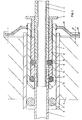
- Fig. 1 eine in der Hauswand unterzubringende Vorrichtung, bei der der Anschlag durch eine in die Kunststoffummantelung des Eisenrohres eingearbeitete Rille gebildet ist,
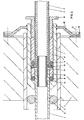
- Fig. 2 eine Vorrichtung, bei der der Anschlag durch einen Bundring auf einem in das Ende des Eisenrohres eingeschraubten Nippel gebildet ist,
- Fig. 3 eine Ausführungsform, bei der der Anschlag durch einen am Ende des Eisenrohres angebrachten Flansch gebildet ist,
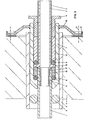
- Fig. 4 eine Ausführungsform, bei der der Anschlag durch einen Flansch an einem Nippel gebildet ist, der in das Ende des Eisenrohres eingeschraubt ist,
- Fig. 5 eine Ausführungsform mit schlauchförmigen Dichtungsringen,
- Fig. eine Ausführungsform mit axial unverschiebbar, aber drehbar auf dem Eisenrohr angeordneter Schraubhülse.
- Das Kunststoffrohr 1 leitet Gas durch das Erdreich aus dem Gesamtnetz und führt es einem im Inneren des Hauses verlegten Eisenrohr 2 zu, welches eine Kunststoffummantelung 3 trägt. In den gezeichneten Ausführungsbeispielen ist die Verbindungsstelle zwischen dem Kunststoffgasrohr 1 und dem Eisenrohr 2 im Inneren der Hauswand 4 angeordnet. In diese Hauswand 4 ist ein Isolierstoffrohrstück 5 eingemauert. Eine Dichtung zwischen dem Isolierstoffrohrstück 5 und dem Kunststoffgasrohr 1 ist durch einen eingelegten Dichtring 6 gewährleistet.
- Die die Verbindung zwischen dem Kunststoffgasrohr 1 und dem Eisengasrohr 2 herstellende Verschraubung besteht aus einer Hülse 7, in der zwei Dichtringe 8, 9 eingelegt sind, von denen der Dichtring 8 dem Kunststoffrohr 1 zugeordnet ist, während der Dichtring 9 dem Eisenrohr 2 zugeordnet ist. Zwischen den beiden Dichtringen 8, 9 liegt ein Distanzring 10, der die beiden Dichtringe 8, 9 auf dem erforderlichen Abstand hält. Diese beiden Dichtringe 8, 9 werden durch eine Schraube oder eine Mutter, in den gezeichneten Ausführungsbeispielen durch die mit Außengewinde versehene Schraubhülse 11, gequetscht, so daß sie sich fest dichtend außen an die Hülse und innen an das Kunststoffrohr bzw. das Eisenrohr bzw. die Ummantelung 3 des Eisenrohres 2 anlegen.
- In den gezeichneten Ausführungsbeispielen ist noch ein weiterer Distanzring zwischen der Schraubhülse 11 und dem Dichtring 9 angeordnet. Dieser weitere Distanzring 12 ermöglicht es, die Schraubhülse 11 kurz auszuführen und trotzdem die Verbindungsstelle zwischen dem Kunststoffgasrohr 1 und dem Eisenrohr 2 tief im Inneren der Wand 4 anzuordnen.
- Im Ausführungsbeispiel der Fig. 1 ist der den festen Sitz der Verschraubung exakt sichernde Anschlag durch eine Rille 13 der Kunststoffummantelung 3 des Eisenrohres 2 gebildet. In diese Rille 13 rutscht der Ring 9 hinein und zentriert durch seinen Sitz in der Rille 13 die einzelnen Teile der Verschraubung, die beim Einschrauben der Schraubhülse 11 sicherstellen, daß alle Teile der Verschraubung so sitzen, daß ein ungewolltes Lösen der Teile voneinander nicht möglich ist. Hierdurch ist gewährleistet, daß der Dichtring 8 an einem Ort liegt, so in dem Eisenrohr 2, das in diesem Ausführungsbeispiel die metallische Hülse für das Abstützen des Kunststoffgasrohres 1 in dessen Inneren bildet, die Rille 14 angeordnet ist, in die das Kunststoffgasrohr 1 an dieser Stelle unter Verengung hineingepreßt wird.
- In dem Ausführungsbeispiel der Fig. 2 ist diese Rille 14 in einem Nippel 15 untergebracht, der einen Bundring 16 trägt, welcher als Anschlag für den Dichtring 9 dient und der in ein Innengewinde am Ende des Eisenrohres 2 eingeschraubt ist.
- Im Ausführungsbeispiel der Fig. 3 ist die Rille 14 in einer Hülse 17 eingebracht, welche am Ende einen Flansch aufweist und welches in das Ende des Kunststoffgasrohres 1 eingeschoben ist. In diesem Ausführungsbeispiel der Fig. 3 dient als Anschlag ein Flansch 18, der am Ende des Eisenrohres 2 angebracht ist.
- Im Ausführungsbeispiel der FIg.4 ist dieser Flansch 18 auf einem Nippel 19 angebracht, der in das Innengewinde am Ende des Eisenrohres 2 eingeschraubt ist.
- Die Hülse 7 der Verschraubung ist in dem in der Wand 4 eingemauerten Isolierstoffrohrstück 5 in den gezeichneten Ausführungsbeispielen dadurch befestigt bzw. gesichert, daß auf der Hülse 7 eine Feuerschutzscheibe 20 angebracht ist. Diese ist im Querschnitt gekröpft ausgeführt. Sie ist mittels nicht dargestellter Schrauben an den Stellen 21 an der Hauswand befestigt. Der Rand der Feuerschutzscheibe 20 trägt einen Isolierring 22, der zweckmäßigerweise am Rande einen Kragen aufweist, mit dem er den Umfang der Feuerschutzscheibe 20 überfaßt, wodurch er auf dieser gehalten wird. Dieser Isolierstoffring dient einer elektrischen Isolierung der Feuerschutzscheibe 20 von der Wand, so daß Korrosion hervorrufende Ströme nicht auf die Feuerschutzscheibe 20 gelangen können. Im Ausführungsbeispiel der Fig. 1 ist die Feuerschutzscheibe 20 auf die Hülse 7 aufgeschweißt. Im Ausführungsbeispiel der Fig. 4 trägt die Hülse 7 einen Anschlagring 23 sowie ein Außengewinde, auf welches die Mutter 24 geschraubt ist, die die Feuerschutzscheibe 20 gegen den Anschlag 23 drückt und dadurch einen festen Sitz der Feuerschutzscheibe 20 auf der Hülse 7 gewährleistet.
- Es sind auch weitere Befestigungsmöglichkeiten der Feuerschutzscheibe 20 gegeben: Diese kann auf die Schraubhülse 11 aufgesetzt sein, auf die dann noch eine zusätzliche Mutter geschraubt ist. Nach dem Festziehen der Schraubhülse 11, durch das das Quetschen der Dichtringe 8 und 9 erfolgt, wird dann mittels der Mutter die Feuerschutzscheibe gegen die Stirnseite der Hülse 7 geschraubt, wodurch nicht nur die Feuerschutzscheibe 20 befestigt wird, sondern gleichzeitig auch noch die Stellung der Schraubhülse 11 gesichert wird. Da die Feuerschutzscheibe 20 relativ großflächig ist, kann bei den letztgenannten Befestigungsarten für die Feuerschutzscheibe auch ein wärmeisolierender Ring zwischen der Hülse 7 und der Feuerschutzscheibe 20 angebracht sein, der eine Wärmeübertragung von der Feuerschutzscheibe 20 auf die Hülse 7 verhindert.
- Im Ausführungsbeispiel der Fig. 5 sind die beiden Dichtringe 8, 9 schlauchförmiger Gestalt. Sie sind auch als Abschnitte eines Schaluches hergestellt. Die beiden Dichtringe weisen gleichen Außendurchmesser auf, der dem Außendurchmesser der Hülse 7 entspricht. Sie weisen jedoch unterschiedliche Innendurchmesser auf. Der Innendurchmesser des Dichtringes 8 entspricht dem Außendurchmesser des Kunststoffschlauches 1, der Innendurchmesser des Dichtringes 9 entspricht dem Außendurchmesser der in das Eisenrohr 2 eingearbeiteten Rille 25. Durch diese Bemessung ist sichergestellt, daß der Dichtring 9 schon vor dem Einbau der Vorrichtung als Transportsicherung dient. Denn wenn die Verschraubung an das Eisenrohr 2 angebracht ist, verhindert dieser Dichtring 9, daß die Verschraubung während des Transportes vom Eisenrohr abfallen kann, obwohl die dem Spannen dienende Schraubhülse 11 noch nicht fest in die Hülse 7 der Verschraubung eingeschraubt ist.
- Es besteht die Möglichkeit, auch einen geschlitzten, im Querschnitt keil- oder dreieckförmigen Ring 26 in der Verschraubung anzuordnen, es können zusätzlich und dem Dichtring 9 zugeordnet, auch Keilringpaare in der Verschraubung angeordnet sein.
- Im Ausführungsbeispiel der Fig. 6 ist die Schraubhülse 11 mit ihrem sechskantigen Flansch 11A axial auf dem Eisenrohr 2 dadurch festgelegt, daß kurz vor dem Ende des Eisenrohres 2 in diesem ein ringförmiger Einstich befindlich ist, in den der Sicherungsring (Seegerring) eingesetzt ist und in dem neben dem Sechskantflansch 11A ein im Ausführungsbeispiel keilförmiger Bund 35 am Eisenrohr 2 angearbeitet ist. Der dem Sechskantflansch 11A zugewandte Absatz dieses Bundes 35 verhindert eine Axialverschiebung der Schraubhülse 11. Dabei ist die Schraubhülse 11 völlig frei drehbar. An dem Federring 27 liegt auf der einen Seite die Stirnseite der Schraubhülse 11 an, auf der anderen Seite liegt ein Ring 28 an, an dessen anderer Stirnseite hinwiederum die Dichtung 9 anliegt. Diese Dichtung 9 ist eine Zylinderringdichtung, die schmaler als die Zylinderringdichtung 8 ist und aus etwas härterem Gummi als die Zylinderringdichtung 8 hergestellt ist. Es kann hier aber auch ein üblicher O-Ring verwendet werden. Das Außengewinde 36 auf der Schraubhülse 11 ist in das Innengewinde 37 der Hülse 7 eingeschraubt.
- In der Ausführungsform der Fig. 6 ist die Hülse 7 an demjenigen Ende, an dem sich das Innengewinde 37 und die Feuerschutzscheibe 20 befindet, in ihrem Querschnitt stärker als im mittleren Teil. Dadurch ergibt sich außen ein Absatz, gegen den sich der eine Dicht- und Zentrierring 29 anlegt. Auf dem gegenüberliegenden Ende ist der Querschnitt der Hülse 7 am Ende wieder stärker als im mittleren Bereich, wobei jedoch der Außendurchmesser hier unverändert bleibt.
- Eine andere Art der Befestigung der Feuerschutzscheibe 20 ist in Fig. 5 gezeigt. Hier ist ein aus Isolierstoff hergestellter, im Querschnitt winkelförmig ausgebildeter Ring 37 vorgesehen, der sich gegen einen Bund 23 auf der Hülse 7 anlegt und auf den die Feuerschutzscheibe 20 gesetzt wird. Die Feuerschutzscheibe 20 wird dann mittels einer Mutter 24 unter Zwischenlegung einer weiteren ringförmigen Isolierstoffscheibe 38 befestigt. Hierdurch ist die Feuerschutzscheibe 20 isoliert an der Hülse 7 angebracht, so daß der Isolierring 22 entfallen kann. Bei dieser Ausführungsform kann durch Feuer entstehende Wärme an der Scheibe 20 nicht in die Hülse eindringen.
- Die Befestigung der Feuerschutzscheibe 20 mittels Schweißen, wie es in Fig. 6 dargestellt ist, hat jedoch dann, wenn die Feuerschutzscheibe 20 auf ihrer Außenseite mit einer unbrennbaren thermischen Isolierung versehen wird, den Vorteil, daß durch das Rohr 2 geleitete Wärme in die Hülse 7 übertritt und von dort auf die Feuerschutzscheibe 20 weitergeleitet wird.
Claims (18)
daß die Hülse (7) im Inneren zwischen dem dem Eisenrohr (2) zugeordneten Dichtring (9) und der Schraubhülse (11) mit Außengewinde einen weiteren Distanzring (12) aufweist
und daß vorzugsweise die Hülse (7) in einem Isolierstoffrohrstück (5) untergebracht ist.
daß die Hülse (7) am anderen Ende als Anschlag oder Lager für den Dichtring (8) ausgebildet ist und daß zwischen den Dichtringen (8, 9) ein Distanzring (10) angeordnet ist
daß die Hülse (7) auf dem mit Innengewinde versehenen Ende eine Feuerschutzkappe (20) trägt und daß vorzugsweise die Feuerschutzkappe (20) einen Isolierring (22) trägt und Löcher für das Durchstecken von Schrauben (21) aufweist.
Applications Claiming Priority (2)
| Application Number | Priority Date | Filing Date | Title |
|---|---|---|---|
| DE3023921 | 1980-06-26 | ||
| DE19803023921 DE3023921A1 (de) | 1980-06-26 | 1980-06-26 | Gas-hausanschlussvorrichtung |
Publications (2)
| Publication Number | Publication Date |
|---|---|
| EP0042885A1 EP0042885A1 (de) | 1982-01-06 |
| EP0042885B1 true EP0042885B1 (de) | 1984-11-21 |
Family
ID=6105509
Family Applications (1)
| Application Number | Title | Priority Date | Filing Date |
|---|---|---|---|
| EP19800104001 Expired EP0042885B1 (de) | 1980-06-26 | 1980-07-11 | Gas-Hausanschlussvorrichtung |
Country Status (2)
| Country | Link |
|---|---|
| EP (1) | EP0042885B1 (de) |
| DE (1) | DE3023921A1 (de) |
Families Citing this family (7)
| Publication number | Priority date | Publication date | Assignee | Title |
|---|---|---|---|---|
| DE3209358C1 (de) * | 1982-03-15 | 1983-08-25 | Omniplast GmbH & Co KG, 6332 Ehringshausen | Muffenrohrverbindung für Rohre aus Kunststoffen |
| DE3539487A1 (de) * | 1985-11-07 | 1987-05-14 | Diga Die Gasheizung Gmbh | Hauseinfuehrung |
| DE3542048A1 (de) * | 1985-11-28 | 1987-06-04 | Immanuel Jeschke | Uebergangsstueck in einer transportleitung fuer gase oder fluessigkeiten sowie verfahren und vorrichtung zur montage dieses uebergangsstueckes |
| DE3717225C1 (en) * | 1987-05-22 | 1988-09-29 | Ingo Kloehn | Device for connecting pipelines |
| DE9202834U1 (de) * | 1992-03-04 | 1992-05-07 | Burger-Armaturen GmbH, 5840 Schwerte | Mauerdurchführung |
| CN107166102B (zh) * | 2017-06-20 | 2018-10-19 | 华润燃气投资(中国)有限公司 | 一种用于穿墙、出地面燃气套管及其制作方法 |
| CN115939799A (zh) * | 2022-11-17 | 2023-04-07 | 苏州保邦电气有限公司 | 气密端子 |
Family Cites Families (2)
| Publication number | Priority date | Publication date | Assignee | Title |
|---|---|---|---|---|
| DE1801908A1 (de) * | 1968-10-09 | 1970-06-18 | Borm Walter | Dichtungsanordnung an Wanddurchfuehrungen,Schutzrohren u.dgl.,insbesondere fuer Kunststoffrohrleitungen |
| AT339102B (de) * | 1974-08-16 | 1977-10-10 | Main Gaswerke A G | Verbindung einer gasrohrleitung aus polyathylen mit einer metallischen gasrohrleitung |
-
1980
- 1980-06-26 DE DE19803023921 patent/DE3023921A1/de not_active Withdrawn
- 1980-07-11 EP EP19800104001 patent/EP0042885B1/de not_active Expired
Also Published As
| Publication number | Publication date |
|---|---|
| DE3023921A1 (de) | 1982-01-14 |
| EP0042885A1 (de) | 1982-01-06 |
Similar Documents
| Publication | Publication Date | Title |
|---|---|---|
| DE102005022449A1 (de) | Abstandshalter für die Befestigung eines Gegenstandes an einem eine Dämmschicht aufweisenden Untergrund | |
| EP0042885B1 (de) | Gas-Hausanschlussvorrichtung | |
| DE29609416U1 (de) | Vorrichtung zur Durchführung eines langgestreckten Gegenstandes durch eine Öffnung einer Wand | |
| DE2336478A1 (de) | Montagesystem fuer fluessigkeits- und/ oder gasrohrleitungen | |
| DE3029533C2 (de) | ||
| EP0123195A1 (de) | Schraubmuffe | |
| EP2586934B1 (de) | Sprinkleranschlussbox | |
| DE3308877C2 (de) | ||
| DE8014568U1 (de) | Vorrichtung zur einfuehrung eines gasrohres | |
| DE9414082U1 (de) | Mauerdurchführung mit Zentrier- und Dichteinsatz | |
| DE19649499A1 (de) | Vorrichtung zum Hindurchführen von Strängen, wie Kabeln oder Rohrleitungen durch eine Wand | |
| DE3411642A1 (de) | Baggergesicherte, elektrisch isolierte mauerdurchfuehrung fuer rohrleitungs-hauseinfuehrungen | |
| DE3332367A1 (de) | Gashausanschlussvorrichtung | |
| CH681237A5 (de) | ||
| DE102007059945B3 (de) | Anschlußvorrichtung für die Verbindung einer erdverlegten Gasleitung aus Kunststoff mit einer in einem Gebäude verlegten Stahlleitung | |
| DE3636082C2 (de) | Gas-Hausanschlußvorrichtung | |
| DE4243460C1 (de) | Gasrohrsanierungsanordnung | |
| EP0978675A2 (de) | Mauerdurchführung | |
| DE8016986U1 (de) | Gas-hausanschlussvorrichtung | |
| DE3137792A1 (de) | Hausanschluss-gasleitung | |
| DE2426730C3 (de) | Rohrschelle für den Anschluß von Rohrstutzen an Rohrleitungen | |
| DE9416506U1 (de) | Verbindung zwischen einem Rohr und einem Anschlußelement | |
| DE4309843A1 (de) | Kabelabzweigklemme | |
| DE9310705U1 (de) | Vorrichtung zum Einbau von Rohren durch Wand- und Deckendurchbrüche, insbesondere von sogenannten Hauseinführungen | |
| DE2711360A1 (de) | Schubsicherung fuer rohrverbindungen |
Legal Events
| Date | Code | Title | Description |
|---|---|---|---|
| PUAI | Public reference made under article 153(3) epc to a published international application that has entered the european phase |
Free format text: ORIGINAL CODE: 0009012 |
|
| 17P | Request for examination filed |
Effective date: 19811008 |
|
| AK | Designated contracting states |
Designated state(s): BE CH FR GB NL SE |
|
| GRAA | (expected) grant |
Free format text: ORIGINAL CODE: 0009210 |
|
| AK | Designated contracting states |
Designated state(s): BE CH FR GB LI NL SE |
|
| ET | Fr: translation filed | ||
| PLBE | No opposition filed within time limit |
Free format text: ORIGINAL CODE: 0009261 |
|
| STAA | Information on the status of an ep patent application or granted ep patent |
Free format text: STATUS: NO OPPOSITION FILED WITHIN TIME LIMIT |
|
| 26N | No opposition filed | ||
| EAL | Se: european patent in force in sweden |
Ref document number: 80104001.5 |
|
| PGFP | Annual fee paid to national office [announced via postgrant information from national office to epo] |
Ref country code: GB Payment date: 19960702 Year of fee payment: 17 |
|
| PGFP | Annual fee paid to national office [announced via postgrant information from national office to epo] |
Ref country code: BE Payment date: 19960705 Year of fee payment: 17 |
|
| PGFP | Annual fee paid to national office [announced via postgrant information from national office to epo] |
Ref country code: SE Payment date: 19960710 Year of fee payment: 17 |
|
| PGFP | Annual fee paid to national office [announced via postgrant information from national office to epo] |
Ref country code: FR Payment date: 19960729 Year of fee payment: 17 |
|
| PGFP | Annual fee paid to national office [announced via postgrant information from national office to epo] |
Ref country code: NL Payment date: 19960731 Year of fee payment: 17 |
|
| PGFP | Annual fee paid to national office [announced via postgrant information from national office to epo] |
Ref country code: CH Payment date: 19960926 Year of fee payment: 17 |
|
| PG25 | Lapsed in a contracting state [announced via postgrant information from national office to epo] |
Ref country code: GB Free format text: LAPSE BECAUSE OF NON-PAYMENT OF DUE FEES Effective date: 19970711 |
|
| PG25 | Lapsed in a contracting state [announced via postgrant information from national office to epo] |
Ref country code: SE Effective date: 19970712 |
|
| PG25 | Lapsed in a contracting state [announced via postgrant information from national office to epo] |
Ref country code: LI Free format text: LAPSE BECAUSE OF NON-PAYMENT OF DUE FEES Effective date: 19970731 Ref country code: CH Free format text: LAPSE BECAUSE OF NON-PAYMENT OF DUE FEES Effective date: 19970731 Ref country code: BE Free format text: LAPSE BECAUSE OF NON-PAYMENT OF DUE FEES Effective date: 19970731 |
|
| BERE | Be: lapsed |
Owner name: JESCHKE IMMANUEL Effective date: 19970731 |
|
| PG25 | Lapsed in a contracting state [announced via postgrant information from national office to epo] |
Ref country code: NL Free format text: LAPSE BECAUSE OF NON-PAYMENT OF DUE FEES Effective date: 19980201 |
|
| GBPC | Gb: european patent ceased through non-payment of renewal fee |
Effective date: 19970711 |
|
| REG | Reference to a national code |
Ref country code: CH Ref legal event code: PL |
|
| PG25 | Lapsed in a contracting state [announced via postgrant information from national office to epo] |
Ref country code: FR Free format text: LAPSE BECAUSE OF NON-PAYMENT OF DUE FEES Effective date: 19980331 |
|
| NLV4 | Nl: lapsed or anulled due to non-payment of the annual fee |
Effective date: 19980201 |
|
| EUG | Se: european patent has lapsed |
Ref document number: 80104001.5 |
|
| REG | Reference to a national code |
Ref country code: FR Ref legal event code: ST |