EP0043000B1 - Outil de forage à organes coupants expansibles - Google Patents
Outil de forage à organes coupants expansibles Download PDFInfo
- Publication number
- EP0043000B1 EP0043000B1 EP81104350A EP81104350A EP0043000B1 EP 0043000 B1 EP0043000 B1 EP 0043000B1 EP 81104350 A EP81104350 A EP 81104350A EP 81104350 A EP81104350 A EP 81104350A EP 0043000 B1 EP0043000 B1 EP 0043000B1
- Authority
- EP
- European Patent Office
- Prior art keywords
- shaft
- tool
- bore
- cutting tool
- cutter feed
- Prior art date
- Legal status (The legal status is an assumption and is not a legal conclusion. Google has not performed a legal analysis and makes no representation as to the accuracy of the status listed.)
- Expired
Links
- 238000005553 drilling Methods 0.000 title claims description 60
- 238000005520 cutting process Methods 0.000 claims abstract description 82
- 238000006073 displacement reaction Methods 0.000 claims abstract description 8
- 230000000295 complement effect Effects 0.000 claims description 6
- 238000003780 insertion Methods 0.000 claims description 6
- 230000037431 insertion Effects 0.000 claims description 6
- 230000006835 compression Effects 0.000 claims description 3
- 238000007906 compression Methods 0.000 claims description 3
- 238000004519 manufacturing process Methods 0.000 claims description 2
- 239000000463 material Substances 0.000 claims description 2
- 239000011435 rock Substances 0.000 claims 2
- 230000004308 accommodation Effects 0.000 claims 1
- 238000010276 construction Methods 0.000 claims 1
- 230000002035 prolonged effect Effects 0.000 claims 1
- 239000000428 dust Substances 0.000 description 12
- 238000000034 method Methods 0.000 description 9
- 230000008878 coupling Effects 0.000 description 4
- 238000010168 coupling process Methods 0.000 description 4
- 238000005859 coupling reaction Methods 0.000 description 4
- 230000000149 penetrating effect Effects 0.000 description 4
- 239000004575 stone Substances 0.000 description 2
- 230000001771 impaired effect Effects 0.000 description 1
- 230000005764 inhibitory process Effects 0.000 description 1
- 239000002184 metal Substances 0.000 description 1
- 239000000843 powder Substances 0.000 description 1
- 230000036316 preload Effects 0.000 description 1
- 238000003825 pressing Methods 0.000 description 1
Images


Classifications
-
- E—FIXED CONSTRUCTIONS
- E21—EARTH OR ROCK DRILLING; MINING
- E21B—EARTH OR ROCK DRILLING; OBTAINING OIL, GAS, WATER, SOLUBLE OR MELTABLE MATERIALS OR A SLURRY OF MINERALS FROM WELLS
- E21B10/00—Drill bits
- E21B10/26—Drill bits with leading portion, i.e. drill bits with a pilot cutter; Drill bits for enlarging the borehole, e.g. reamers
- E21B10/32—Drill bits with leading portion, i.e. drill bits with a pilot cutter; Drill bits for enlarging the borehole, e.g. reamers with expansible cutting tools
-
- Y—GENERAL TAGGING OF NEW TECHNOLOGICAL DEVELOPMENTS; GENERAL TAGGING OF CROSS-SECTIONAL TECHNOLOGIES SPANNING OVER SEVERAL SECTIONS OF THE IPC; TECHNICAL SUBJECTS COVERED BY FORMER USPC CROSS-REFERENCE ART COLLECTIONS [XRACs] AND DIGESTS
- Y10—TECHNICAL SUBJECTS COVERED BY FORMER USPC
- Y10T—TECHNICAL SUBJECTS COVERED BY FORMER US CLASSIFICATION
- Y10T408/00—Cutting by use of rotating axially moving tool
- Y10T408/83—Tool-support with means to move Tool relative to tool-support
- Y10T408/85—Tool-support with means to move Tool relative to tool-support to move radially
- Y10T408/858—Moving means including wedge, screw or cam
- Y10T408/8588—Axially slidable moving-means
- Y10T408/85884—Tool pivotally mounted on support
-
- Y—GENERAL TAGGING OF NEW TECHNOLOGICAL DEVELOPMENTS; GENERAL TAGGING OF CROSS-SECTIONAL TECHNOLOGIES SPANNING OVER SEVERAL SECTIONS OF THE IPC; TECHNICAL SUBJECTS COVERED BY FORMER USPC CROSS-REFERENCE ART COLLECTIONS [XRACs] AND DIGESTS
- Y10—TECHNICAL SUBJECTS COVERED BY FORMER USPC
- Y10T—TECHNICAL SUBJECTS COVERED BY FORMER US CLASSIFICATION
- Y10T82/00—Turning
- Y10T82/12—Radially moving rotating tool inside bore
- Y10T82/125—Tool simultaneously moving axially
- Y10T82/128—Pivoted to tool-carrier
Definitions
- the invention relates to a drilling tool for producing undercuts in pilot holes in masonry, concrete, stone and.
- a rotatably drivable tool shaft that can be inserted into the pilot hole to be provided with the undercut, in the end region of which at least one cutting tool is arranged such that its cutting edge can gradually be displaced radially outward into the wall of the pilot hole after the shaft has been inserted into the pilot hole, wherein the cutting tool is arranged on a pivotable in a longitudinal slot-like recess in the bore-inner end portion of the tool shank, designed as a two-armed lever cutting tool carrier, which through the bore-inner end of a longitudinally displaceable but rotationally penetrating through the tool shaft, with its outer end from the outer end End of the tool shank led out feed shaft from a position pivoted back into the slot-like recess by inserting the feed shaft into the tool shaft into a position in which the cutting tool from the tool shank.
- the machined drilling dust from the wall of the hole is placed in the recess in the cutting tool holder, it can happen in isolated cases that the swiveling of the cutting tool holder into the recess, which is necessary after the drilling process, is hindered, and the force of the spring is not sufficient to retract the cutting tool completely into the recess, so that additional manipulations are required to remove the undercut tool from the bore.
- the cutting tool is swiveled back into the tool shaft after completion of the undercut after the cam has been withdrawn either only by pressure exerted on the cutting tools by the wall of the hole when the entire drilling tool is withdrawn from the bore (DE-B-1207907) or a link-like connection which additionally supports this pressure between the infeed shank and the cutting tool holder, in which a pin from the infeed shaft engages in a cam slot in the cutting tool holder (CH-A-495492).
- the invention has for its object to increase the drilling performance of the drilling tool compared to the known drilling tool in that a comparatively higher radial feed force can be exerted on the cutting tool, both when pivoting the cutting tool during the undercut drilling process and when retracting of the cutting tool after the drilling process against any inhibitions caused by drilling dust which may have penetrated into the interior of the tool.
- the cutting tool carrier has on its rear side opposite the cutting tool on its bore-inside lever arm a pressure surface which is inclined to the direction of displacement of the feed shaft which engages a delivery cam formed on the inside of the bore of the feed shank, which pivots the bore-inside lever arm of the cutting tool carrier when the feed shaft shifts relative to the tool shaft into the bore with an increasingly larger lever arm out of the recess of the tool shaft, and that the back of the bore-mouth lever arm of the cutting tool carrier is one Lever arm inside the bore has oppositely inclined pressure surface on which the feed cam engages out of the bore inside when the feed shank is displaced relative to the tool shank.
- the feed shaft in the area led out of the tool shaft on the one hand and on the tool shaft Delivery shaft supports supported coil springs that are under pressure.
- the helical spring is expediently supported on the bore-mouth end face of the tool shank on the one hand and the end face of a collar component provided on the feed shank on the other hand, whereby it may be expedient to design the collar component in selectable axial positions on the area of the feed shank protruding from the tool shank, since in this way the Bias of the coil spring is changeable.
- the helical spring is expediently arranged within a sleeve attached to the end of the tool shank, in which the front end of the collar component facing the bore engages in a longitudinally displaceable manner.
- the coil spring is therefore completely encapsulated within the sleeve.
- the rotationally fixed and longitudinally displaceable coupling of the feed shank to the tool shank is brought about by a pin provided in a transverse bore in the tool shank and penetrating an elongated hole in the feed shank.
- this coupling can also take place in that a section provided with a multi-wedge profile is provided on the feed shaft, which is arranged in a sleeve section of the tool shaft provided with a complementary multi-wedge profile in a rotationally fixed but longitudinally displaceable manner.
- the feed shank in its area led out of the tool shank is designed as a multi-wedge shank section, which at its front end facing the tool shank is still partly in a sleeve-shaped section of the tool shank with an inner multi-wedge profile complementary to the multi-wedge profile of the multi-wedge shank section engages, the sleeve section provided with the multi-wedge profile being dimensioned such that the multi-wedge shaft section can be displaced into the sleeve section by the amount required for pivoting the cutting tool carrier.
- a resilient return of the feed shank relative to the tool shank can be provided to simplify the handling of the tool, in that a compression spring supported on the front end face of the multi-spline shank section on the one hand and on the bottom of the sleeve section on the tool shank on the other hand is provided in the sleeve section is arranged.
- a functional improvement of the tools designed in the manner according to the invention is achieved in that the slot-like recess for receiving the cutting tool carrier extends into the section of the tool shank lying in front of the cutting tool carrier in the insertion direction and to a receiving pocket for the material worked out by the cutting tool from the wall of the pilot hole (drilling dust ) is designed. Obstacles to the pivoting-out process of the cutting tool carrier due to drilling dust collecting in the recess are thus avoided.
- the feed shank can be drilled in the middle over its entire length for this purpose, so that it On the cutting tool side, the bore opens into the recess in the tool shank that receives the cutting tool carrier.
- a device for extracting the drilling dust from the machine-side mouth of the bore must then be provided in the drive machine receiving the drilling tool.
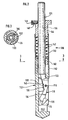
- the drilling tool according to the invention shown in the drawing designated in its entirety by 10, for drilling an undercut in a cylindrical pilot hole previously produced in a customary manner in an underground of stone, concrete, masonry or the like has a tool shank 12, in which in the A front-end region to be introduced into the pre-bore is provided with a longitudinal slot-like recess 14 that is open on one side.
- a cutting tool carrier 18 is mounted on a bolt 16 in the form of a flat, elongated, two-armed lever fitted in the width of the recess 14, on the lever arm 18a on the inside of the bore, which is located in the drawing below, on the front side facing the open side of the recess
- the actual cutting tool 20 is arranged, which is formed, for example, by a hard metal plate which is hard-soldered into a suitable receptacle of the cutting tool carrier 18 and on which the cutting edges which are designed in accordance with the shape of the undercut to be produced are ground.
- the tool shank 12 has a longitudinal center bore 22 extending from its outer bore end to the recess 14, in which a feed shank 24 is inserted so as to be longitudinally displaceable but non-rotatable, which still emerges from the tool shank 12 to a considerable extent.
- the rotation is secured by a pin 30 penetrating a transverse bore 26 in the tool shank 12 and an elongated hole 28 in the additional shank 24.
- the longitudinal center bore and the feed shank could also - at least in a partial area - be complementarily polygonal in cross section, e.g. B. be square or hexagonal, or the rotation of the shafts 12, 24 relative to each other can alternatively be prevented by a tongue and groove connection.
- the free end of the end of the feed shaft 24 protruding from the tool shaft 12 is designed as a hexagon at 32.
- the back of the lever arm 18a of the cutting tool carrier 18, which is opposite the cutting tool 20, is designed as a pressure surface 34 which extends obliquely to the direction of displacement of the infeed shaft 24, namely its inclination is selected such that it relates to the right in relation to the position of the drilling tool shown in the drawing opening recess 14 runs from top right to bottom left.
- a feed cam 36 attached to the lower end of the feed shaft 24 and guided past the rear of the second lever arm 18b on the bore mouth side can be brought into contact with the pressure surface 34 by pushing the feed shaft into the tool shaft with its somewhat rounded front end.
- the delivery cam 36 supported with its rear side on the closed side of the recess urges the pressure surface 34, i. H.
- the rear of the lever arm 18b on the bore mouth side of the cutting tool carrier 18 is also designed as a pressure surface 38, which is inclined in the opposite direction to the pressure surface 34.
- the complementarily inclined surface 40 of the feed cam 36 runs against the pressure surface 40 and inevitably pivots the cutting tool carrier 18 when the feed shank 24 is retracted in such a way that the cutting tool 20 is returned to the recess 14.
- the drilling tool 10 is already functional to the extent described so far, but its handling is improved in practice in that a helical spring 42 surrounding it is arranged in the area of the delivery shaft 24 which is led out of the tool shaft 12, the lower end of which is on the bore mouth side End face of the tool shank 12 is supported, while its other end rests under pressure on the end face facing the bore of a collar component 44 pushed onto the feed shank 24 and fastened thereon.
- a collar component can be fastened in selectable axial positions on the feed shaft 24 in a radial threaded bore 46 screwed into the collar component 44.
- the bias of the coil spring 24 can therefore be changed to a certain extent.
- the coil spring 42 is surrounded by a sleeve 50 which is attached to the end of the tool shank 12 and in the other end of which the collar component 44 fits d. H. engages longitudinally.
- An enlarged receiving pocket 52 which continues the recess 14 in the insertion direction and continues the recess 14, serves to receive the drilling dust worked out by the cutting tool 20 from the wall of a pilot hole. Jamming of the cutting tool carrier 18 in the pivoted-out position by accumulated in the recess 14 behind the pivoted-out cutting tool carrier This avoids drilling dust. Even if drilling dust should have accumulated in this area, it is displaced into the receiving pocket 52 when the delivery shaft is pulled back.
- the drilling tool 110 shown in FIGS. 2 and 3 differs from the drilling tool 10 described above essentially only in the manner of the rotationally fixed but longitudinally displaceable coupling of the feed and tool shafts, so that it is sufficient to describe only this coupling below, while referring to the general description of the drilling tool 110, the foregoing description.
- the parts of the drilling tool 110 which correspond to the parts of the drilling tool 10 are identified by the same reference numerals, but with the preceding 1.
- the feed shaft 124 of the drilling tool 110 carries a pressed-on or otherwise rigidly fastened multi-wedge body 160 which engages in a sleeve section 162 provided with a complementary multi-wedge profile at the rear end of the tool shaft 112, the length of the sleeve section 162 in relation to the multi-wedge body 160 is dimensioned such that the multi-wedge body 160 can be pushed into the sleeve section 162 against the action of the spring 142 by the feed path required for the pivoting of the cutting tool carrier 118.
- the feed shank 124 is provided with a continuous longitudinal center bore 164, which makes it possible for the drilling dust which collects when working with the tool 110 in the recess 114 receiving the cutting tool carrier 118 to be continuously sucked off if the drive machine for the tool has a corresponding suction device is provided.
- the rotationally fixed and longitudinally displaceable connection of the feed shank 224 to the tool shank 212 takes place by means of a multi-spline connection.
- the area of the feed shank 224 which is led out of the tool shank 212 is designed overall as a multi-wedge shank section 260 which, at its front end facing the tool shank 212, engages somewhat in a sleeve-shaped section 262 at the rear end of the tool shank.
- this sleeve-shaped section 262 is provided with a multi-wedge profile that is complementary to the multi-spline profile of the shaft section 260, as a result of which a positive connection between the shaft section 260 and the sleeve section 262 is provided in the direction of rotation of the tool.
- the sleeve section 262 is in turn dimensioned such that the multi-wedge shaft section 260 can be pushed into the sleeve section 262 by the required feed path.
- the compression spring 242 which supports the restoration, is supported between the front end face 261 of the multi-spline shank section 260 on the one hand and on the bottom 263 of the sleeve section 262 on the tool shank 212 on the other hand.
- the feed shaft 224 can be provided with a longitudinal center bore 264 (FIG. 5) for suctioning off the drilling dust during the drilling process.
Landscapes
- Engineering & Computer Science (AREA)
- Geology (AREA)
- Life Sciences & Earth Sciences (AREA)
- Mining & Mineral Resources (AREA)
- Physics & Mathematics (AREA)
- Environmental & Geological Engineering (AREA)
- Fluid Mechanics (AREA)
- Mechanical Engineering (AREA)
- General Life Sciences & Earth Sciences (AREA)
- Geochemistry & Mineralogy (AREA)
- Processing Of Stones Or Stones Resemblance Materials (AREA)
- Earth Drilling (AREA)
- Drilling And Boring (AREA)
Claims (11)
Priority Applications (1)
| Application Number | Priority Date | Filing Date | Title |
|---|---|---|---|
| AT81104350T ATE7325T1 (de) | 1980-06-30 | 1981-06-05 | Hinterschnitt-bohrwerkzeug. |
Applications Claiming Priority (2)
| Application Number | Priority Date | Filing Date | Title |
|---|---|---|---|
| DE3024656 | 1980-06-30 | ||
| DE3024656A DE3024656C2 (de) | 1980-06-30 | 1980-06-30 | Hinterschnitt-Bohrwerkzeug |
Publications (2)
| Publication Number | Publication Date |
|---|---|
| EP0043000A1 EP0043000A1 (fr) | 1982-01-06 |
| EP0043000B1 true EP0043000B1 (fr) | 1984-05-02 |
Family
ID=6105980
Family Applications (1)
| Application Number | Title | Priority Date | Filing Date |
|---|---|---|---|
| EP81104350A Expired EP0043000B1 (fr) | 1980-06-30 | 1981-06-05 | Outil de forage à organes coupants expansibles |
Country Status (7)
| Country | Link |
|---|---|
| US (1) | US4411324A (fr) |
| EP (1) | EP0043000B1 (fr) |
| JP (1) | JPS5739915A (fr) |
| AT (1) | ATE7325T1 (fr) |
| CA (1) | CA1157464A (fr) |
| DE (1) | DE3024656C2 (fr) |
| ES (1) | ES503444A0 (fr) |
Families Citing this family (41)
| Publication number | Priority date | Publication date | Assignee | Title |
|---|---|---|---|---|
| US4502554A (en) * | 1982-06-02 | 1985-03-05 | Jones Richard H | Expansible tool for reaming frustoconical undercuts in cylindrical holes |
| US4586573A (en) * | 1982-06-02 | 1986-05-06 | Jones Richard H | Rotary expansion tool for reaming frustoconical undercuts in the walls of cylindrical holes |
| JPS59184608A (ja) * | 1983-04-05 | 1984-10-20 | 産機興業株式会社 | 穿孔拡開ドリル |
| DE3327409A1 (de) * | 1983-07-29 | 1985-02-07 | Hawera Probst Gmbh + Co, 7980 Ravensburg | Bohrwerkzeug zur herstellung von hinterschneidungen in vorgefertigten bohrungen |
| JPS60145005U (ja) * | 1984-03-08 | 1985-09-26 | 株式会社ミヤナガ | 拡径孔部削成装置 |
| US4635737A (en) * | 1984-03-08 | 1987-01-13 | Kabushiki Kaishi Miyanaga | Undercutting drill |
| US4630978A (en) * | 1985-10-03 | 1986-12-23 | Terry L. Keiser | Thread chasing tool |
| IT1204117B (it) * | 1986-01-28 | 1989-03-01 | Luciano Frazzoli | Attrezzo per eseguire lamature su macchine utensili in particolare all'estremita' non accessibile di fori passanti |
| JPH0829445B2 (ja) * | 1986-12-16 | 1996-03-27 | 株式会社ミヤナガ | 上向き拡径孔部削成装置 |
| JPH01148214U (fr) * | 1988-03-30 | 1989-10-13 | ||
| DE3818079A1 (de) * | 1988-05-27 | 1989-12-07 | Plica Werkzeugfabrik Ag | Fraeswerkzeug und verfahren zum ausfraesen zylindrischer bohrloecher |
| DE3819833C2 (de) * | 1988-06-10 | 1998-05-07 | Drebo Werkzeugfab Gmbh | Dübelbohrer |
| GB2223550A (en) * | 1988-09-16 | 1990-04-11 | Water Res Centre | Pipe tapping |
| DE3839617A1 (de) * | 1988-11-24 | 1990-05-31 | Fischer Artur Werke Gmbh | Vorrichtung zur herstellung einer hinterschneidung in einem bohrloch |
| DE3909481A1 (de) * | 1989-03-22 | 1990-09-27 | Adolf Wuerth Gmbh & Co Kg | Bohrwerkzeug |
| DE69005547T2 (de) * | 1989-07-14 | 1994-06-23 | David Patrick Payne | Bohrer. |
| US5086852A (en) * | 1990-08-27 | 1992-02-11 | Wada Ventures | Fluid flow control system for operating a down-hole tool |
| GB2297052B (en) * | 1995-01-23 | 1998-02-18 | David Patrick Payne | Improvements in drills |
| JP2862830B2 (ja) * | 1996-03-13 | 1999-03-03 | 株式会社ミヤナガ | アンダーカット部付き孔の穿孔装置 |
| US5800148A (en) * | 1997-12-03 | 1998-09-01 | Wise; Michael A. | Blind-taper hole saw |
| US5927911A (en) * | 1998-10-19 | 1999-07-27 | R. Steiner Technologies, Inc. | Automatic fluid actuated spotfacing and counterboring tool |
| EP1622499A2 (fr) * | 2003-04-17 | 2006-02-08 | Secant Medical, LLC | Outil a lame de coupe pouvant etre deployee |
| CN1315627C (zh) * | 2004-09-24 | 2007-05-16 | 徐洁媛 | 一种深孔绞刀具 |
| JP2006095658A (ja) * | 2004-09-30 | 2006-04-13 | Asahi Maintenance Kogyo:Kk | 管体の切削及び/又は切断装置 |
| US7357613B2 (en) * | 2006-01-26 | 2008-04-15 | Simpson Strong -Tie Company, Inc. | Expansion anchor with crack-arresting groove |
| EP2313223A4 (fr) * | 2008-07-18 | 2012-01-04 | Sandvik Inc | Outil d'alésage inverse avec actionnement par agent de refroidissement |
| DE102008044802B4 (de) * | 2008-08-28 | 2014-10-23 | Edith & Gerhard Esberger GbR | Werkzeug zur spanabhebenden Bearbeitung von in einem Gestell fest eingespannten Werkstücken |
| US8122978B1 (en) | 2009-05-05 | 2012-02-28 | John Clifford | Drilling device with undercutting |
| DE102012005246A1 (de) * | 2012-03-14 | 2013-09-19 | Ulf Heule | Entgratwerkzeug zur Entgratung von insbesondere unrunden Ausnehmungen in Werkstücken |
| US9089905B1 (en) * | 2012-05-30 | 2015-07-28 | The Boeing Company | Omni-directional deburring blade |
| KR101675451B1 (ko) * | 2013-08-23 | 2016-11-11 | 가부시키 가이샤 미야나가 | 확경 구멍부가 있는 구멍의 천공 장치 |
| CN103603602B (zh) * | 2013-10-29 | 2016-08-17 | 河南理工大学 | 变推力变径钻 |
| US20150313611A1 (en) * | 2014-05-02 | 2015-11-05 | Howmedica Osteonics Corp. | Undercutting bone drills and methods of use |
| BR122022014776B1 (pt) | 2014-10-19 | 2023-12-26 | T.A.G. Medical Devices - Agriculture Cooperative Ltd | Conjunto incluindo um sistema de orientação e dispositivo para remoção de material ósseo e método para perfuração de um túnel ósseo em um osso |
| US10448959B2 (en) * | 2015-04-09 | 2019-10-22 | T.A.G. Medical Devices—Agriculture Cooperative Ltd. | Bone material removal device and a method for use thereof |
| WO2017137998A2 (fr) | 2016-02-11 | 2017-08-17 | T.A.G. Medical Devices - Agriculture Cooperative Ltd. | Dispositif de retrait de matière osseuse et procédé pour l'utiliser |
| US11020132B2 (en) | 2016-04-24 | 2021-06-01 | T.A.G. Medical Devices—Agriculture Cooperative Ltd. | Guiding device and method of using thereof |
| US10808481B2 (en) | 2017-11-16 | 2020-10-20 | Weatherford Technology Holdings, Llc | Apparatus and method for cutting casings |
| CA3105930C (fr) | 2018-08-01 | 2023-01-31 | T.A.G. Medical Devices - Agriculture Cooperative Ltd. | Dispositif de percage reglable et son procede d'utilisation |
| US11780015B2 (en) * | 2021-06-08 | 2023-10-10 | Noga Engineering & Technology (2008) Ltd. | Machining tool with deployable blade |
| EP4122629A1 (fr) | 2021-07-19 | 2023-01-25 | Fundación Tekniker | Mécanisme d'actionnement pour le mouvement radial d'un outil de coupe d'une barre de forage |
Family Cites Families (15)
| Publication number | Priority date | Publication date | Assignee | Title |
|---|---|---|---|---|
| US473909A (en) * | 1892-05-03 | Rock-drilling apparatus | ||
| US165787A (en) * | 1875-07-20 | Improvement in expansion-drills | ||
| US226067A (en) * | 1880-03-30 | Peters | ||
| US1045670A (en) * | 1912-01-04 | 1912-11-26 | Arthur P Buck | Well-reaming implement. |
| US1450053A (en) * | 1921-07-11 | 1923-03-27 | Expansion Drill Company | Expansion drill |
| US1955631A (en) * | 1933-06-22 | 1934-04-17 | Laurence V D Harris | Counter boring tool |
| US2203011A (en) * | 1937-04-08 | 1940-06-04 | Guy P Ellis | Pipe cutter |
| US2202986A (en) * | 1939-07-24 | 1940-06-04 | James T Ellis | Pipe cutter |
| US2599060A (en) * | 1951-02-09 | 1952-06-03 | Archer W Kammerer | Expansible rotary drill bit |
| DE1191769B (de) * | 1960-03-11 | 1965-04-29 | Archer William Kammerer | Erweiterungsrollenmeissel |
| DE1207907B (de) * | 1962-09-07 | 1965-12-30 | Servco Co | Bohrlochwerkzeug |
| GB1184106A (en) * | 1967-04-18 | 1970-03-11 | John Darbyshire & Company Ltd | Improvements in or relating to Reamers |
| CH495492A (de) * | 1968-12-31 | 1970-08-31 | Navenby Ltd | Bohrwerkzeug zum Herstellen von Ankerbohrungen im Erdreich |
| US3684041A (en) * | 1970-11-16 | 1972-08-15 | Baker Oil Tools Inc | Expansible rotary drill bit |
| DE2731901A1 (de) * | 1977-07-14 | 1979-02-01 | Heinrich Liebig | Hinterschnitt-bohrwerkzeug |
-
1980
- 1980-06-30 DE DE3024656A patent/DE3024656C2/de not_active Expired
-
1981
- 1981-06-05 EP EP81104350A patent/EP0043000B1/fr not_active Expired
- 1981-06-05 AT AT81104350T patent/ATE7325T1/de not_active IP Right Cessation
- 1981-06-22 CA CA000380357A patent/CA1157464A/fr not_active Expired
- 1981-06-26 ES ES503444A patent/ES503444A0/es active Granted
- 1981-06-29 US US06/278,558 patent/US4411324A/en not_active Expired - Fee Related
- 1981-06-30 JP JP56100720A patent/JPS5739915A/ja active Pending
Also Published As
| Publication number | Publication date |
|---|---|
| EP0043000A1 (fr) | 1982-01-06 |
| DE3024656A1 (de) | 1982-01-21 |
| US4411324A (en) | 1983-10-25 |
| CA1157464A (fr) | 1983-11-22 |
| ES8204334A1 (es) | 1982-05-16 |
| ES503444A0 (es) | 1982-05-16 |
| ATE7325T1 (de) | 1984-05-15 |
| JPS5739915A (en) | 1982-03-05 |
| DE3024656C2 (de) | 1982-08-12 |
Similar Documents
| Publication | Publication Date | Title |
|---|---|---|
| EP0043000B1 (fr) | Outil de forage à organes coupants expansibles | |
| EP0434924B1 (fr) | Dispositif pour forer un puits adjacent ou dévié à partir d'un puits, notamment d'un puits tubé | |
| DE10357810B4 (de) | Drehbarer Einsatz mit einer elastischen, spielbehafteten Sicherungshülse | |
| DE3234552C2 (de) | Vorrichtung zum Herstellen eines Gesteinsbohrlochs | |
| DE2602238A1 (de) | Bohrkrone | |
| CH616355A5 (fr) | ||
| CH678834A5 (fr) | ||
| DE3507817A1 (de) | Bohrer zur erzeugung einer hinterschneidung in einer bohrung | |
| DE2409629A1 (de) | Bergbauliches vortriebswerkzeug (drehschaftmeissel) | |
| DE69004316T2 (de) | Bohrwerkzeug. | |
| DE69119402T2 (de) | Im bohrloch zu gebrauchendes bohrwerkzeug zum bohren vor einer verrohrung | |
| EP3323556A1 (fr) | Appareil de fixation comprenant des arbres d'entraînement pouvant être bloqués axialement, procédé de fixation et ancre extensible associée | |
| EP0065284B1 (fr) | Alésoir | |
| DE60025395T2 (de) | Verriegelbare bohrstange sowie aufnahme | |
| EP0343653B1 (fr) | Outil à fraiser et procédé pour agrandir des trous de type cylindrique | |
| DE102019008156A1 (de) | Fräsmeißel für eine Bodenfräsmaschine, Montageeinheit mit einem solchen Fräsmeißel und einer Spannschraube, Meißelhalter, Meißelhaltersystem, Fräswalze und Bodenfräsmaschine sowie Verfahren zur Montage eines Fräsmeißels in einem Meißelhalter | |
| EP0808696B1 (fr) | Système de fixation et procédé de réalisation de fixations | |
| DE1533700B1 (de) | Bohrmeissel zum Eintreiben eines Futterrohres in das Bohrloch | |
| DE2652366C2 (de) | Hinterschnitt-Bohrwerkzeug | |
| DE19527138C1 (de) | Vorrichtung zum Ersetzen einer alten Versorgungsleitung durch eine neue Leitung | |
| DE2305133A1 (de) | Bohrvorrichtung mit einer bohrspindel und einem in senkrechter ebene vor dieser bewegbaren magazin | |
| CH632311A5 (en) | Drilling tool for drilling holes widening in the drilling direction | |
| EP0211997A1 (fr) | Outil de chambrage | |
| DE2621809A1 (de) | Bohreinrichtung mit einem auswechselbaren gesteinsbohrer, insbesondere einem schlagbohrer, einem hammerbohrer u.dgl. | |
| EP0334806A1 (fr) | Couronne de forage de roche |
Legal Events
| Date | Code | Title | Description |
|---|---|---|---|
| PUAI | Public reference made under article 153(3) epc to a published international application that has entered the european phase |
Free format text: ORIGINAL CODE: 0009012 |
|
| AK | Designated contracting states |
Designated state(s): AT BE CH FR GB IT NL SE |
|
| 17P | Request for examination filed |
Effective date: 19820122 |
|
| ITF | It: translation for a ep patent filed | ||
| GRAA | (expected) grant |
Free format text: ORIGINAL CODE: 0009210 |
|
| AK | Designated contracting states |
Designated state(s): AT BE CH FR GB IT LI NL SE |
|
| REF | Corresponds to: |
Ref document number: 7325 Country of ref document: AT Date of ref document: 19840515 Kind code of ref document: T |
|
| PGFP | Annual fee paid to national office [announced via postgrant information from national office to epo] |
Ref country code: FR Payment date: 19840529 Year of fee payment: 4 |
|
| ET | Fr: translation filed | ||
| PGFP | Annual fee paid to national office [announced via postgrant information from national office to epo] |
Ref country code: SE Payment date: 19840630 Year of fee payment: 4 Ref country code: BE Payment date: 19840630 Year of fee payment: 4 |
|
| PGFP | Annual fee paid to national office [announced via postgrant information from national office to epo] |
Ref country code: CH Payment date: 19840710 Year of fee payment: 4 |
|
| PLBE | No opposition filed within time limit |
Free format text: ORIGINAL CODE: 0009261 |
|
| STAA | Information on the status of an ep patent application or granted ep patent |
Free format text: STATUS: NO OPPOSITION FILED WITHIN TIME LIMIT |
|
| 26N | No opposition filed | ||
| PGFP | Annual fee paid to national office [announced via postgrant information from national office to epo] |
Ref country code: AT Payment date: 19860620 Year of fee payment: 6 |
|
| PGFP | Annual fee paid to national office [announced via postgrant information from national office to epo] |
Ref country code: NL Payment date: 19870630 Year of fee payment: 7 |
|
| PG25 | Lapsed in a contracting state [announced via postgrant information from national office to epo] |
Ref country code: GB Effective date: 19880605 Ref country code: AT Effective date: 19880605 |
|
| PG25 | Lapsed in a contracting state [announced via postgrant information from national office to epo] |
Ref country code: SE Effective date: 19880606 |
|
| PG25 | Lapsed in a contracting state [announced via postgrant information from national office to epo] |
Ref country code: LI Effective date: 19880630 Ref country code: CH Effective date: 19880630 |
|
| BERE | Be: lapsed |
Owner name: LIEBIG HEINRICH Effective date: 19880630 |
|
| PG25 | Lapsed in a contracting state [announced via postgrant information from national office to epo] |
Ref country code: NL Effective date: 19890101 |
|
| NLV4 | Nl: lapsed or anulled due to non-payment of the annual fee | ||
| GBPC | Gb: european patent ceased through non-payment of renewal fee | ||
| PG25 | Lapsed in a contracting state [announced via postgrant information from national office to epo] |
Ref country code: FR Free format text: LAPSE BECAUSE OF NON-PAYMENT OF DUE FEES Effective date: 19890228 |
|
| REG | Reference to a national code |
Ref country code: CH Ref legal event code: PL |
|
| REG | Reference to a national code |
Ref country code: FR Ref legal event code: ST |
|
| PG25 | Lapsed in a contracting state [announced via postgrant information from national office to epo] |
Ref country code: BE Effective date: 19890630 |
|
| EUG | Se: european patent has lapsed |
Ref document number: 81104350.4 Effective date: 19890220 |