EP0043105A2 - Système de rétrocouplage pour la pression engendrée par une charge, comportant au moins une valve de commande - Google Patents
Système de rétrocouplage pour la pression engendrée par une charge, comportant au moins une valve de commande Download PDFInfo
- Publication number
- EP0043105A2 EP0043105A2 EP81104907A EP81104907A EP0043105A2 EP 0043105 A2 EP0043105 A2 EP 0043105A2 EP 81104907 A EP81104907 A EP 81104907A EP 81104907 A EP81104907 A EP 81104907A EP 0043105 A2 EP0043105 A2 EP 0043105A2
- Authority
- EP
- European Patent Office
- Prior art keywords
- load
- arm
- control
- load pressure
- pressures
- Prior art date
- Legal status (The legal status is an assumption and is not a legal conclusion. Google has not performed a legal analysis and makes no representation as to the accuracy of the status listed.)
- Granted
Links
- 210000000056 organ Anatomy 0.000 claims abstract description 6
- 210000000245 forearm Anatomy 0.000 claims abstract description 5
- 230000001276 controlling effect Effects 0.000 abstract description 2
- 230000001105 regulatory effect Effects 0.000 abstract description 2
- 230000011664 signaling Effects 0.000 abstract 1
- 230000001133 acceleration Effects 0.000 description 1
- 230000005540 biological transmission Effects 0.000 description 1
- 230000000694 effects Effects 0.000 description 1
- 230000002349 favourable effect Effects 0.000 description 1
- 230000003068 static effect Effects 0.000 description 1
Images


Classifications
-
- B—PERFORMING OPERATIONS; TRANSPORTING
- B25—HAND TOOLS; PORTABLE POWER-DRIVEN TOOLS; MANIPULATORS
- B25J—MANIPULATORS; CHAMBERS PROVIDED WITH MANIPULATION DEVICES
- B25J3/00—Manipulators of leader-follower type, i.e. both controlling unit and controlled unit perform corresponding spatial movements
- B25J3/04—Manipulators of leader-follower type, i.e. both controlling unit and controlled unit perform corresponding spatial movements involving servo mechanisms
Definitions
- the invention relates to a load pressure feedback system with at least one control valve for controlling a device, in particular a manipulator consisting of a slave member or load arm with an upper arm rotatably hinged to a base part or the like and a forearm hinged thereon including the load-receiving end and from a master arm which is reduced in size and which can be moved by hand as a donor member or control part, the joints or pivot bearings of the slave member or load arm and the donor member or master arm being connected to one another.
- a manipulator consisting of a slave member or load arm with an upper arm rotatably hinged to a base part or the like and a forearm hinged thereon including the load-receiving end and from a master arm which is reduced in size and which can be moved by hand as a donor member or control part, the joints or pivot bearings of the slave member or load arm and the donor member or master arm being connected to one another.
- US Pat. No. 3,171,549 discloses a manipulator as a mechanically operating handling device; in which gripping jaws arranged on a movable carrier can grasp a load and can transport it from one location to another.
- the valve has a hydraulic pilot control part, in which the load measuring points prevailing at the device are present at the inlet of at least one throttle orifice, the height of the control pressures being determined by the opening cross sections of the throttle orifice or a screw-in orifice, and at least a control piston is acted upon on the one hand by the load pressures and on the other hand by the control pressures.
- the hydraulic load pressure control valve which preferably has control edges, is provided with orifices and determines the ratio of their opening cross sections for the control pressures.
- a piston of the load pressure control valve has also proven to be favorable, which is acted upon by the outlet pressures and which interacts with a control piston, which in turn is acted on by secondary pressures.
- control piston and its counter-piston can also be under spring load.
- the load pressure control valve is assigned at least one pressure reducing valve, and these valves are arranged on a row plate.
- the cross section of the throttle diaphragm should be changeable according to the invention.
- the comparison of the setpoint voltages with the actual value voltages leads to differential voltages which cause the servo valves and thus the corresponding cantilevers to deflect.
- the actual value voltage corresponds to the setpoint voltage and the difference signal disappears, the specified position is reached - the cantilevers remain.
- the deflection of the rotary movement is directly mechanically removed from the master arm by means of a copying valve or a corresponding organ and, according to the invention, the speed is determined by the size of a deflection angle in relation to a central position forced by energy stores.
- electro-hydraulic load-force feedback is provided in parallel to the mechanical position control.
- the base part of the master arm is rotatably supported on an axis which is connected to the hydraulic gear motor of the load arm via a miniature swivel cylinder or a corresponding element and the load pressure control valve.
- the miniature cylinders or the like provided on the base of the transmitter element or the master arm can also be connected to a hydraulic cylinder of the load arm or slave element via a load pressure control valve and a servo valve.
- a spreader cylinder is connected between the arm parts of the master arm or master element via a load pressure control valve and a servo valve to a corresponding spreader cylinder of the load arm or slave element.
- a manipulator M consists of a master arm 1 according to FIG. 1, which controls a load arm 2 according to FIG. 3 connected to it via an electro-hydraulic position control; the master arm 1 is essentially a reduced replica of the load arm 2.
- a model upper arm 4 with model lower arm 5 protrudes from a base 3 of the master arm 1 and is connected to one another by an (elbow) joint 6. At the free end of the model upper arm 5 there is a (hand) joint 7 for a control handle 7.
- the other end of the model upper arm 4 is fixed on an axis 8 and also rigidly connected to a lever arm 9 which is articulated at 10 to a piston 11; this is connected to a miniature cylinder 12, which in turn is articulated at 13 on the base 3.
- Return springs 14 and 16 are provided between base 3 and model upper arm 4 and between the latter and model lower arm 5, and an expansion cylinder 17 is articulated on both sides between upper arm 4 and lower arm 5.
- the base 3 is seated on the piston axis 18 of a swing cylinder 19 and is in the direction of arrow z pivotable at an angle of ⁇ 10 0; Centering springs 20 which act horizontally on both sides hold the base 3 - and thus the entire master arm 1 - in the central position illustrated in FIG. 2.
- An oblique end face 21 of the base 3, as a control cam, is in contact with a roller tappet 22 of a mechanical copy valve 23, which is connected to a hydraulic geared motor 26 via lines 24, 25.
- Lines 27, 28 lead from the swivel cylinder 19 with the interposition of a row plate 29 to a load pressure control valve 30.
- the miniature cylinder 12 is connected on the one hand by lines 31, 32 and on the other hand the spreading cylinder 17 present between the upper arm 4 and forearm 5 is connected to other load pressure control valves 30m and 30n by lines 33, 34.
- the first-mentioned load pressure control valve 30 is connected to the hydraulic gear motor 26 by lines 35, 36. Adjustable throttle orifices 37 are inserted into these lines 35, 36, as are also assigned to the other load pressure control valves 30m and 30n - in each case in connecting lines 38, 39 and 40, 41 to a hydraulic cylinder 12a and a spreading cylinder 17a on the load arm 2
- Adjustable throttle orifices 37 are inserted into these lines 35, 36, as are also assigned to the other load pressure control valves 30m and 30n - in each case in connecting lines 38, 39 and 40, 41 to a hydraulic cylinder 12a and a spreading cylinder 17a on the load arm 2
- an index "a" (3a; 4a; 5a; 6a; 8a; 9a; 10a; 11a; 12a; 13a ; 17a; 18a).
- the load pressures are branched off from the connecting lines 38, 39 between the hydraulic cylinder 12a of the load arm 2 and a servo valve 50 via control lines 40, 41 and fed to the load pressure control valve 30m. This applies correspondingly to lines 42, 43 between spreading cylinder 17a and an associated servo valve 50 n with control lines 44, 45.
- the load pressure control valves 30, 30m, 30n and a pressure reducing valve 52 with an intermediate plate 51 are combined on a common row plate or a control block 29.
- the actual value voltage corresponds to the target value voltage and the difference signal is thus at 0
- the position specified by master arm 1 is reached and the arms 4a and 5a of load arm 2 remain.
- the deflection of the copy valve 23 is carried out directly mechanically.
- the pivoting direction of the manipulator M is predetermined by the movement of the control handle 7 g to the right or left (+ or -) and the speed by the size of the deflection angle Z.
- the center position is - as described - guaranteed by the centering springs 20 on the base 3.
- a load / force feedback system is effective, which transmits the pressure conditions in the working cylinders 12a, 17a and the hydraulic gear motor 26 to the associated actuators 12 (miniature cylinders), 17 (spreading cylinders) and 19 (swivel cylinders).
- the load pressures are applied to the load pressure control valves 30, 30m or 30 n via the adjustable throttle orifices 37; these regulate the outlet pressures in proportion to the corresponding inlet pressure.
- the maximum pressure levels of the output pressures can be set independently of one another by adjusting the throttle orifices 37 / 37m / 37n, which makes it possible to set the feedback force on the control handle 7 g .
- the adjustable return springs 14, 16 prevent the master arm 1 from dropping when the system pressure is switched off.
- the system pressure is reduced to the permissible inlet pressure for the load pressure control valves 30, 30 m or 30 n.
- This load pressure control valves 30, 30m°. 30 n serve to achieve a load or force feedback of the desired movements without technically complex electronic pressure control circuits; they regulate the pressures in the corresponding actuators of the master arm 1 directly and hydraulically in proportion to the prevailing load pressures of the actuators.
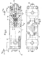
- the load pressure control valve 30 is described below with reference to FIGS. 4 to 6.
- a control sleeve 61 with O-rings 62 can be seen as a seal, and then a fastening nut 63.
- a stop 64 which is also sealed by O-rings 62 and has an outer nut 65, projects into the interior thereof.
- the load pressure P38 or P39 prevailing on the respective actuators (hydraulic cylinder, hydraulic gear motor, etc.) of the manipulator M is present at the input of the adjustable throttle orifice 37n or 37.
- control pressures PST 38 and PST 39 each act on a piston 69 which is in equilibrium with control pistons 70 acted on the opposite side by the secondary pressures P385 and P39 '.
- the maximum control range of the control pressures PST 38 or PST 39 and thus the secondary outlet pressures P38 or P39 can be changed.
- the force effect on master arm 1 and thus the load or force transmission ratio between manipulator M and master arm 1 can be set.
- the maximum deflection of the control piston 70 can be limited by the stops 64 and thus be set.
- springs 74 ensure that the control pistons 70 bear against the pistons 69 and 70 and relieve the load on the downstream system.
- the stop 64 is in each case arranged in the separate end cover 76, which sits on the housing 60 with the interposition of O-rings 62 m.
- the stop 64 is set here by pressurization via pressure spaces 77.
Landscapes
- Engineering & Computer Science (AREA)
- Robotics (AREA)
- Mechanical Engineering (AREA)
- Manipulator (AREA)
- Servomotors (AREA)
Applications Claiming Priority (2)
| Application Number | Priority Date | Filing Date | Title |
|---|---|---|---|
| DE19803024402 DE3024402A1 (de) | 1980-06-28 | 1980-06-28 | Manipulator aus lastarm und meisterarm |
| DE3024402 | 1980-06-28 |
Publications (3)
| Publication Number | Publication Date |
|---|---|
| EP0043105A2 true EP0043105A2 (fr) | 1982-01-06 |
| EP0043105A3 EP0043105A3 (en) | 1982-01-20 |
| EP0043105B1 EP0043105B1 (fr) | 1986-03-05 |
Family
ID=6105781
Family Applications (1)
| Application Number | Title | Priority Date | Filing Date |
|---|---|---|---|
| EP81104907A Expired EP0043105B1 (fr) | 1980-06-28 | 1981-06-25 | Système de rétrocouplage pour la pression engendrée par une charge, comportant au moins une valve de commande |
Country Status (5)
| Country | Link |
|---|---|
| US (1) | US4516894A (fr) |
| EP (1) | EP0043105B1 (fr) |
| JP (1) | JPS57500969A (fr) |
| DE (2) | DE3024402A1 (fr) |
| WO (1) | WO1982000112A1 (fr) |
Cited By (3)
| Publication number | Priority date | Publication date | Assignee | Title |
|---|---|---|---|---|
| FR2515090A1 (fr) * | 1981-10-23 | 1983-04-29 | Atomic Energy Authority Uk | Manipulateur muni d'un circuit de reaction entre l'organe commande et la commande |
| EP0506622A1 (fr) * | 1991-03-13 | 1992-09-30 | METRA METALLURGICA TRAFILATI ALLUMINIO S.p.A. | Ensemble de profilés et de dispositifs de fixation pour réaliser des façades de bâtiments continues |
| DE102004057938B4 (de) * | 2004-11-30 | 2008-09-18 | GAT Gesellschaft für Antriebstechnik mbH | Vorrichtung zum aktiven Verstellen bewegbarer Elemente an einem rotierenden Maschinenteil |
Families Citing this family (3)
| Publication number | Priority date | Publication date | Assignee | Title |
|---|---|---|---|---|
| GB2273282B (en) * | 1992-12-10 | 1997-06-04 | O Brien Brian J | Powered variable geometry structural unit |
| DE4446145A1 (de) * | 1994-12-23 | 1996-06-27 | Bosch Gmbh Robert | Hydraulische Steuerung in Monoblockbauweise zum Heben und Senken einer Last mit mindestens zwei elektromagnetisch betätigbaren Proportionalwegeventilelementen |
| US6508058B1 (en) | 2001-03-15 | 2003-01-21 | Louis A. Seaverson | Hydraulic control system with tactile force and position feedback |
Family Cites Families (15)
| Publication number | Priority date | Publication date | Assignee | Title |
|---|---|---|---|---|
| DE1082718B (de) * | 1955-10-10 | 1960-06-02 | Wilhelm Ludowici Dr Ing | Einrichtung zur Steuerung der Bewegung von lastenfoerdernden Geraeten |
| US3123230A (en) * | 1960-03-15 | 1964-03-03 | Manipulators | |
| US3168203A (en) * | 1960-07-07 | 1965-02-02 | Gen Mills Inc | Manually operated hydraulic actuator control having feel-back |
| GB1106472A (en) * | 1964-07-31 | 1968-03-20 | Atomic Energy Authority Uk | Remote-control manipulator |
| GB966609A (fr) * | 1965-03-10 | 1900-01-01 | ||
| US3422965A (en) * | 1967-02-13 | 1969-01-21 | Westinghouse Electric Corp | Manipulator apparatus |
| US3618786A (en) * | 1969-01-02 | 1971-11-09 | Gen Electric | Material-handling apparatus with end effector force resolver and feedback |
| US3698580A (en) * | 1969-12-22 | 1972-10-17 | Int Harvester Co | Control system for material handling equipment |
| CA919553A (en) * | 1970-02-18 | 1973-01-23 | Hitachi, Ltd. | Hydraulic operating apparatus |
| US3637092A (en) * | 1970-04-30 | 1972-01-25 | Gen Electric | Material-handling apparatus |
| US3608743A (en) * | 1970-05-04 | 1971-09-28 | Gen Electric | Material-handling apparatus |
| US3712180A (en) * | 1970-11-27 | 1973-01-23 | Gen Electric | Bilateral servo controlled manipulator |
| FR2158124B1 (fr) * | 1971-11-04 | 1974-10-31 | Gen Electric | |
| US3880304A (en) * | 1972-02-11 | 1975-04-29 | Jr William A Strickland | Mimic positioning controller for a hydraulically actuated back hoe |
| FR2348020A1 (fr) * | 1976-04-12 | 1977-11-10 | Signaux Entr Electriques | Structure articulee perfectionnee du genre compas, notamment pour manipulateurs industriels |
-
1980
- 1980-06-28 DE DE19803024402 patent/DE3024402A1/de not_active Withdrawn
-
1981
- 1981-06-25 DE DE8181104907T patent/DE3173965D1/de not_active Expired
- 1981-06-25 EP EP81104907A patent/EP0043105B1/fr not_active Expired
- 1981-06-27 JP JP56502311A patent/JPS57500969A/ja active Pending
- 1981-06-27 US US06/355,585 patent/US4516894A/en not_active Expired - Fee Related
- 1981-06-27 WO PCT/DE1981/000099 patent/WO1982000112A1/fr not_active Ceased
Cited By (4)
| Publication number | Priority date | Publication date | Assignee | Title |
|---|---|---|---|---|
| FR2515090A1 (fr) * | 1981-10-23 | 1983-04-29 | Atomic Energy Authority Uk | Manipulateur muni d'un circuit de reaction entre l'organe commande et la commande |
| US4537547A (en) * | 1981-10-23 | 1985-08-27 | The United Kingdom Atomic Energy Authority | Manipulator |
| EP0506622A1 (fr) * | 1991-03-13 | 1992-09-30 | METRA METALLURGICA TRAFILATI ALLUMINIO S.p.A. | Ensemble de profilés et de dispositifs de fixation pour réaliser des façades de bâtiments continues |
| DE102004057938B4 (de) * | 2004-11-30 | 2008-09-18 | GAT Gesellschaft für Antriebstechnik mbH | Vorrichtung zum aktiven Verstellen bewegbarer Elemente an einem rotierenden Maschinenteil |
Also Published As
| Publication number | Publication date |
|---|---|
| WO1982000112A1 (fr) | 1982-01-21 |
| EP0043105A3 (en) | 1982-01-20 |
| EP0043105B1 (fr) | 1986-03-05 |
| DE3024402A1 (de) | 1982-01-21 |
| JPS57500969A (fr) | 1982-06-03 |
| DE3173965D1 (en) | 1986-04-10 |
| US4516894A (en) | 1985-05-14 |
Similar Documents
| Publication | Publication Date | Title |
|---|---|---|
| DE2651325C2 (fr) | ||
| EP0321890B1 (fr) | Dispositif manipulateur | |
| DE2000013A1 (de) | Manipulator | |
| DE1456438C3 (de) | Druckmittelregelschaltung für eine mit einer Verschiebezylinderanordnung ausbalancierte Trag- und Einstellvorrichtung | |
| DE3709504C2 (de) | Ventileinrichtung | |
| DE1082718B (de) | Einrichtung zur Steuerung der Bewegung von lastenfoerdernden Geraeten | |
| EP0043105A2 (fr) | Système de rétrocouplage pour la pression engendrée par une charge, comportant au moins une valve de commande | |
| DE3819122A1 (de) | Verfahren und vorrichtung zur regelung der position von stellventilen | |
| DE202010008424U1 (de) | Handhabungsgerät | |
| DE3913655C2 (fr) | ||
| DE3800990A1 (de) | Handhabungsgeraet | |
| DE3413913A1 (de) | Verstelleinrichtung fuer das verdraengungsvolumen einer verdraengermaschine | |
| DE4140423A1 (de) | Vorrichtung zur einstellung des arbeitsfluessigkeitsdruckes | |
| DE2409207C3 (de) | Lenkeinrichtung mit hydraulischer Hilfskraftunterstützung für schwere Kraftfahrzeuge | |
| DD226241A1 (de) | Schaltungsanordnung zur kraft- bzw. momentenrueckfuehrung fuer manipulatoren | |
| DE2457212A1 (de) | Hydraulische stellvorrichtung mit nullastpunktverschiebung | |
| DE2819133C3 (de) | Einrichtung zum automatischen Ausbalancieren des Gewichtes des Stössels samt Werkzeugoberteil einer mechanischen Presse | |
| DE2234563C3 (de) | Stellanordnung zur Einstellung einer Steuerfläche | |
| DE3121340A1 (de) | Druckmittelbetaetigte steuereinrichtung | |
| DE950171C (de) | Einrichtung zur Belastung von Steuerungen von am Boden befindlichen Fluguebungsgeraeten | |
| DE1576165C (de) | Verteilervorrichtung für ein Druckmittel, das zwei doppeltwirkende hydraulische Motoren beaufschlagt | |
| DE1073228B (de) | Summenrelais zur Storwertaufschaltung bei Reglern mit pneumatischer Hilfskraft | |
| DE3407781C2 (fr) | ||
| WO2005084413A1 (fr) | Systeme d'alimentation | |
| DE3703004A1 (de) | Hydraulische servo-stellvorrichtung fuer ein bewegliches teil eines fluggeraets |
Legal Events
| Date | Code | Title | Description |
|---|---|---|---|
| PUAI | Public reference made under article 153(3) epc to a published international application that has entered the european phase |
Free format text: ORIGINAL CODE: 0009012 |
|
| PUAL | Search report despatched |
Free format text: ORIGINAL CODE: 0009013 |
|
| AK | Designated contracting states |
Designated state(s): DE FR GB SE |
|
| AK | Designated contracting states |
Designated state(s): DE FR GB SE |
|
| RBV | Designated contracting states (corrected) |
Designated state(s): DE FR GB SE |
|
| 17P | Request for examination filed |
Effective date: 19820308 |
|
| GRAA | (expected) grant |
Free format text: ORIGINAL CODE: 0009210 |
|
| AK | Designated contracting states |
Kind code of ref document: B1 Designated state(s): DE FR GB SE |
|
| REF | Corresponds to: |
Ref document number: 3173965 Country of ref document: DE Date of ref document: 19860410 |
|
| ET | Fr: translation filed | ||
| PLBE | No opposition filed within time limit |
Free format text: ORIGINAL CODE: 0009261 |
|
| STAA | Information on the status of an ep patent application or granted ep patent |
Free format text: STATUS: NO OPPOSITION FILED WITHIN TIME LIMIT |
|
| 26N | No opposition filed | ||
| PG25 | Lapsed in a contracting state [announced via postgrant information from national office to epo] |
Ref country code: GB Effective date: 19890625 |
|
| PG25 | Lapsed in a contracting state [announced via postgrant information from national office to epo] |
Ref country code: SE Effective date: 19890626 |
|
| GBPC | Gb: european patent ceased through non-payment of renewal fee | ||
| PG25 | Lapsed in a contracting state [announced via postgrant information from national office to epo] |
Ref country code: FR Free format text: LAPSE BECAUSE OF NON-PAYMENT OF DUE FEES Effective date: 19900228 |
|
| PG25 | Lapsed in a contracting state [announced via postgrant information from national office to epo] |
Ref country code: DE Effective date: 19900403 |
|
| REG | Reference to a national code |
Ref country code: FR Ref legal event code: ST |
|
| EUG | Se: european patent has lapsed |
Ref document number: 81104907.1 Effective date: 19900412 |