EP0043140A1 - Presse à granuler - Google Patents
Presse à granuler Download PDFInfo
- Publication number
- EP0043140A1 EP0043140A1 EP19810105095 EP81105095A EP0043140A1 EP 0043140 A1 EP0043140 A1 EP 0043140A1 EP 19810105095 EP19810105095 EP 19810105095 EP 81105095 A EP81105095 A EP 81105095A EP 0043140 A1 EP0043140 A1 EP 0043140A1
- Authority
- EP
- European Patent Office
- Prior art keywords
- mold
- press
- shaft
- cube
- stand
- Prior art date
- Legal status (The legal status is an assumption and is not a legal conclusion. Google has not performed a legal analysis and makes no representation as to the accuracy of the status listed.)
- Granted
Links
- 239000008188 pellet Substances 0.000 title description 2
- 238000005452 bending Methods 0.000 claims description 7
- 230000003014 reinforcing effect Effects 0.000 claims description 4
- 238000003825 pressing Methods 0.000 description 4
- 238000003860 storage Methods 0.000 description 3
- 230000002787 reinforcement Effects 0.000 description 2
- 230000003749 cleanliness Effects 0.000 description 1
- 238000010276 construction Methods 0.000 description 1
- 230000007423 decrease Effects 0.000 description 1
- 230000002349 favourable effect Effects 0.000 description 1
- 238000012423 maintenance Methods 0.000 description 1
- 238000004519 manufacturing process Methods 0.000 description 1
- 239000000463 material Substances 0.000 description 1
- 238000005457 optimization Methods 0.000 description 1
- 239000007787 solid Substances 0.000 description 1
Images


Classifications
-
- B—PERFORMING OPERATIONS; TRANSPORTING
- B30—PRESSES
- B30B—PRESSES IN GENERAL
- B30B11/00—Presses specially adapted for forming shaped articles from material in particulate or plastic state, e.g. briquetting presses, tabletting presses
- B30B11/20—Roller-and-ring machines, i.e. with roller disposed within a ring and co-operating with the inner surface of the ring
- B30B11/201—Roller-and-ring machines, i.e. with roller disposed within a ring and co-operating with the inner surface of the ring for extruding material
Definitions
- the invention relates to a cube press, in particular a feed cube press, with a shaft which carries a support for two or more press rolls which are arranged within an annular press mold, and with a mold carrier for the press mold which is arranged about the shaft so as to be rotatable relative to the latter.
- the shaft is clamped in a stand.
- the mold carrier is rotatably mounted on the shaft. So that on the other side of the mold the access to its interior is free and allows a convenient arrangement of the feed device, as well as easy access to the press rollers and their adjusting device, which determines the distance between the press rollers and the mold.
- a disadvantage arises from the short free bending length of the shaft compared to the mold carrier because of the bearing. If the distances between the press rolls and the inside of the mold are unequal, the closest press roll is overloaded and the press mold is stressed accordingly more at this point. The rigid mutual support of the mold carrier and shaft prevents the overloaded press roll from escaping, and the mold thus remains overloaded on one side. Storage is also heavily used.
- the invention aims to avoid these disadvantages. Your job is to allow the use of thinner dies. Furthermore, the cube press itself and in particular its storage should be exposed to less high stresses. By clearly mastering the forces involved, the effort for the press and its maintenance should be reduced.
- the cube press according to the invention is characterized in that the shaft and / or the mold carrier is or are at least partially elastic in order to allow a uniform loading or deformation of the preform.
- a compact and clear structure of the cube press results when a self-supporting tube piece is attached to the stand, which surrounds a part of the shaft at a distance and carries the bearings of the mold carrier, so that viewed along the axis of the machine, this tube piece between the clamping point of the shaft in Stand on the one hand and the mold on the other.
- the shaft is clamped in the stator via two spherical bearings, the flexibility of the shaft is improved by extending the bending line.
- a uniform deformation of the mold over its width is achieved in that the mold carrier has a hub around its bearings, which is connected to the mold receiver by an elongated, thin, preferably cylindrical ring.
- the thickness of the ring should preferably be from 0.02 to 0.005 of the inside diameter of the mold, in particular 0.005. Given the large diameter of this ring, its flexural strength is so great that it only needs to be calculated for twisting, so that in certain cases the value can be less than 0.005.
- the shape sensor in a manner known per se as a wear ring, preferably with a clamping wedge arranged in a circle for fastening the preform.
- a reinforcing ring can be provided on the side opposite the wear ring, which is preferably fastened to the mold with similar clamping wedges and which at most carries a cover for the mold.
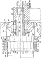
- the press rollers 13, 14 are mounted on eccentric pins 17, 18, the foot parts 19, 20 of which are supported by a support 21.
- the support 21 is carried by a shaft 24 clamped in the stand 23.
- a lever 26 is fastened on this shaft 24 by a wedge 27.
- the lever 26 and thus the shaft 24 are fixedly connected to the stand 23 by a breaking pin 28, so that rotation of the support 21 is not possible in normal operation.
- the shaft For storage, the shaft carries two collars 31, 32, which transmit radial forces to the stand 23 via a bushing 33.
- the eccentric pins 17, 18 are provided with means 35, not shown in detail, for example from CH-PSs 416 291 and 454 592, which determine their angular position in the support 21, such that the distances between the press rolls 13, 14 and the press mold 11 are individual can be fixed.
- a self-supporting tube piece 37 is attached, which surrounds a part of the shaft 24 at a distance.
- This piece of pipe 37 lies between the clamping point 31, 32, 33 of the shaft 23 on the one hand and the die 11 on the other. It carries the bearings 39, 40 of the hub 41 of the mold carrier 42.
- a drive wheel 43 shown with a reduced diameter, is attached to the hub 41.
- the grooves 44 of the drive wheel 43 which are only shown in part, indicate a V-belt drive.
- An elongated, thin, cylindrical ring 46 fastened to the hub 41 connects this hub 41 via a collar 47 to the shape sensor 50 designed as a wear ring 49.
- the collar 47 is screwed to both the ring 46 and the wear ring 49.
- the pressing mold 11 is fastened in the wear ring 49 in a known manner with axially clampable clamping wedges 53 arranged on a circle.
- On the opposite side of the Pre3form 11 a similarly designed reinforcing ring 55 is attached, which is fastened with similar clamping wedges 56 on the pressing mold 11 and which carries a cover 57 with a central opening 58.
- the function of the cube press described is as follows: The distances between the press rolls 13, 14 and the press mold 11 are set to the desired same value with the aid of the means 35.
- the drive wheel 43 drives the press mold 11 via the mold carrier 42 and the mold receiver 50.
- the product is fed through the central opening 58 and is fed in equal parts to the press rollers 13, 14 by means, not shown, for example from CH-PS 316 845 or US Pat. No. 2,764,951.
- the product is drawn in between the press rollers 13 and 14 and the mold 11 and pressed out through the pre-bores 12.
- the extruded strands are brought to the desired position by knives firmly arranged in the press Cut length to form cubes (also called pellets).
- the support 21 can be adjusted upward without the bending force being too great on the shaft 24.
- the distance between the press roller 14 and the die 11 increases, and the distance between the press roller 13 and the die 11 decreases until the pressing forces on the press rollers 13, 14 are uniform, so that the load on the die 11 is approximately the intended value at the two points reached and an overload of this die 11 does not take place with the press roller 14.
- the shaft 24 must support the support 21 and the press rollers 13, 14, it is advisable not to overdo their elasticity.
- a favorable design is achieved if, with a horizontal arrangement of the shaft, the deflection caused by bending due to the weight of the shaft with press rollers is from 0.00015 to 0.005 of the inside diameter of the press mold, preferably 0.0003 to 0.001, in particular 0.0005.
- the shaft With a press mold with an inner diameter of 660 mm, the shaft has e.g. a diameter of 140 mm, while the free length from the axial seat near the collar 31 to the support 21 for the press rollers 13, 14 is approximately 700 mm.
- the shaft is then dimensioned so that this deflection can be 0.3 mm. This corresponds to a fraction of 0.00045 of the inside diameter of the mold.
- the rings 46 of the mold carrier 42 are advantageously designed such that their thickness is from 0.02 to 0.005 of the inside diameter of the mold 11, in particular 0, UDS.
- the thickness of the ring 46 has been chosen to be 3 mm, while its length is approximately 300 mm.
- the ring 46 offers almost no resistance to ovalizing the die 11, the thickness of which can be 40 to 80 mm.
- the wear ring 49 possibly taking into account the collar 47
- the reinforcement ring 55 are designed with a resistance to ovalization, which has the same order of magnitude as that of the Pre3form 11 itself. This avoids the particularly harmful uneven deformation of the mold 11 along its width.
Landscapes
- Engineering & Computer Science (AREA)
- Mechanical Engineering (AREA)
- Forging (AREA)
- Rolls And Other Rotary Bodies (AREA)
Applications Claiming Priority (2)
| Application Number | Priority Date | Filing Date | Title |
|---|---|---|---|
| CH510080 | 1980-07-02 | ||
| CH5100/80 | 1980-07-02 |
Publications (2)
| Publication Number | Publication Date |
|---|---|
| EP0043140A1 true EP0043140A1 (fr) | 1982-01-06 |
| EP0043140B1 EP0043140B1 (fr) | 1984-02-29 |
Family
ID=4287933
Family Applications (1)
| Application Number | Title | Priority Date | Filing Date |
|---|---|---|---|
| EP19810105095 Expired EP0043140B1 (fr) | 1980-07-02 | 1981-07-01 | Presse à granuler |
Country Status (2)
| Country | Link |
|---|---|
| EP (1) | EP0043140B1 (fr) |
| DE (1) | DE3162429D1 (fr) |
Cited By (3)
| Publication number | Priority date | Publication date | Assignee | Title |
|---|---|---|---|---|
| US4788023A (en) * | 1983-10-31 | 1988-11-29 | Eugen Buhler and Hutschenreuther AG | Process and apparatus for producing a dry-pressed moulding from a particulate or granular moulding material |
| US5626889A (en) * | 1994-12-29 | 1997-05-06 | Andritz Sprout-Bauer, Inc. | Single tapered die mount |
| US5665403A (en) * | 1994-12-29 | 1997-09-09 | Andritz Sprout-Bauer, Inc. | Double tapered die mount |
Families Citing this family (1)
| Publication number | Priority date | Publication date | Assignee | Title |
|---|---|---|---|---|
| US6596303B1 (en) * | 1999-03-22 | 2003-07-22 | Mars Incorporated | Pet food for maintenance of joint health and alleviation of arthritic symptoms in companion animals |
Citations (3)
| Publication number | Priority date | Publication date | Assignee | Title |
|---|---|---|---|---|
| BE504019A (fr) * | ||||
| US3841817A (en) * | 1973-09-19 | 1974-10-15 | A Moldenhauer | Pelletizing apparatus |
| DE2647799A1 (de) * | 1976-10-22 | 1978-04-27 | Buehler Miag Gmbh | Pelletpresse |
-
1981
- 1981-07-01 DE DE8181105095T patent/DE3162429D1/de not_active Expired
- 1981-07-01 EP EP19810105095 patent/EP0043140B1/fr not_active Expired
Patent Citations (3)
| Publication number | Priority date | Publication date | Assignee | Title |
|---|---|---|---|---|
| BE504019A (fr) * | ||||
| US3841817A (en) * | 1973-09-19 | 1974-10-15 | A Moldenhauer | Pelletizing apparatus |
| DE2647799A1 (de) * | 1976-10-22 | 1978-04-27 | Buehler Miag Gmbh | Pelletpresse |
Cited By (3)
| Publication number | Priority date | Publication date | Assignee | Title |
|---|---|---|---|---|
| US4788023A (en) * | 1983-10-31 | 1988-11-29 | Eugen Buhler and Hutschenreuther AG | Process and apparatus for producing a dry-pressed moulding from a particulate or granular moulding material |
| US5626889A (en) * | 1994-12-29 | 1997-05-06 | Andritz Sprout-Bauer, Inc. | Single tapered die mount |
| US5665403A (en) * | 1994-12-29 | 1997-09-09 | Andritz Sprout-Bauer, Inc. | Double tapered die mount |
Also Published As
| Publication number | Publication date |
|---|---|
| EP0043140B1 (fr) | 1984-02-29 |
| DE3162429D1 (en) | 1984-04-05 |
Similar Documents
| Publication | Publication Date | Title |
|---|---|---|
| DE2813781C2 (de) | Hochleistungs-Rührwerkskugelmühle | |
| EP0295449B1 (fr) | Dispositif pour imprimer ou découper à l'emporte-pièce une bande | |
| DE19635845C1 (de) | Kalanderwalze mit einem Bezug aus elastischem Kunststoff | |
| DE2812958C2 (fr) | ||
| DE3221011C2 (fr) | ||
| DE2055147C3 (de) | Walzenpresse | |
| DE3443032C1 (de) | Schneidscheibenmaschine,insbesondere zum Schneiden von Zuckerrueben | |
| EP0043140B1 (fr) | Presse à granuler | |
| EP1031274A1 (fr) | Rouleau pour machine à récolter | |
| CH625999A5 (fr) | ||
| DE3006450C2 (fr) | ||
| DE19826324C1 (de) | Walzenschüsselmühle | |
| EP3461325A1 (fr) | Rouleau pour une presse à balles agricole | |
| DE3142779C2 (de) | Vollmantel-Schnecken-Zentrifuge | |
| DE2203855A1 (de) | Vorrichtung zum Zusammenpressen von faserigem Material, insbesondere von Futter, in eine agglomerierte Form | |
| DE2732108A1 (de) | Seilfuehrung und eine solche seilfuehrung aufweisende winde | |
| AT240681B (de) | Verstellvorrichtung für Doppelbacken-Walzenbrecher | |
| EP1740309A1 (fr) | Moulin a cylindres | |
| DE3441434A1 (de) | Ziehdrahthaspelanordnung mit, einen doppeltrommelblock bildender obertrommel und untertrommel | |
| EP0380671A1 (fr) | Cylindre | |
| EP3631059B1 (fr) | Cylindre pour une carde | |
| CH653408A5 (de) | Verstelleinrichtung fuer die leitschaufeln einer axialturbomaschine. | |
| DE3447690C2 (fr) | ||
| DE2542109A1 (de) | Vorrichtung zur zerkleinerung und/oder mischung von festen, pastoesen oder fluessigen stoffen | |
| DE7716192U1 (de) | Treibscheibentriebwerk |
Legal Events
| Date | Code | Title | Description |
|---|---|---|---|
| PUAI | Public reference made under article 153(3) epc to a published international application that has entered the european phase |
Free format text: ORIGINAL CODE: 0009012 |
|
| AK | Designated contracting states |
Designated state(s): DE FR GB IT NL |
|
| 17P | Request for examination filed |
Effective date: 19811111 |
|
| GRAA | (expected) grant |
Free format text: ORIGINAL CODE: 0009210 |
|
| AK | Designated contracting states |
Designated state(s): DE FR GB IT NL |
|
| PG25 | Lapsed in a contracting state [announced via postgrant information from national office to epo] |
Ref country code: NL Effective date: 19840229 Ref country code: IT Free format text: LAPSE BECAUSE OF FAILURE TO SUBMIT A TRANSLATION OF THE DESCRIPTION OR TO PAY THE FEE WITHIN THE PRESCRIBED TIME-LIMIT;WARNING: LAPSES OF ITALIAN PATENTS WITH EFFECTIVE DATE BEFORE 2007 MAY HAVE OCCURRED AT ANY TIME BEFORE 2007. THE CORRECT EFFECTIVE DATE MAY BE DIFFERENT FROM THE ONE RECORDED. Effective date: 19840229 Ref country code: FR Free format text: THE PATENT HAS BEEN ANNULLED BY A DECISION OF A NATIONAL AUTHORITY Effective date: 19840229 |
|
| REF | Corresponds to: |
Ref document number: 3162429 Country of ref document: DE Date of ref document: 19840405 |
|
| NLV1 | Nl: lapsed or annulled due to failure to fulfill the requirements of art. 29p and 29m of the patents act | ||
| EN | Fr: translation not filed | ||
| PLBE | No opposition filed within time limit |
Free format text: ORIGINAL CODE: 0009261 |
|
| STAA | Information on the status of an ep patent application or granted ep patent |
Free format text: STATUS: NO OPPOSITION FILED WITHIN TIME LIMIT |
|
| 26N | No opposition filed | ||
| PG25 | Lapsed in a contracting state [announced via postgrant information from national office to epo] |
Ref country code: DE Effective date: 19850402 |
|
| GBPC | Gb: european patent ceased through non-payment of renewal fee | ||
| PG25 | Lapsed in a contracting state [announced via postgrant information from national office to epo] |
Ref country code: GB Effective date: 19881118 |