EP0043177A1 - Procédé et appareil pour enlever la chair du squelette de poissons - Google Patents
Procédé et appareil pour enlever la chair du squelette de poissons Download PDFInfo
- Publication number
- EP0043177A1 EP0043177A1 EP19810200751 EP81200751A EP0043177A1 EP 0043177 A1 EP0043177 A1 EP 0043177A1 EP 19810200751 EP19810200751 EP 19810200751 EP 81200751 A EP81200751 A EP 81200751A EP 0043177 A1 EP0043177 A1 EP 0043177A1
- Authority
- EP
- European Patent Office
- Prior art keywords
- rollers
- fish
- pair
- squeeze
- squeeze rollers
- Prior art date
- Legal status (The legal status is an assumption and is not a legal conclusion. Google has not performed a legal analysis and makes no representation as to the accuracy of the status listed.)
- Granted
Links
- 241000251468 Actinopterygii Species 0.000 title claims abstract description 85
- 238000000034 method Methods 0.000 title claims abstract description 17
- XLYOFNOQVPJJNP-UHFFFAOYSA-N water Substances O XLYOFNOQVPJJNP-UHFFFAOYSA-N 0.000 claims description 19
- 239000007921 spray Substances 0.000 claims description 6
- 210000001015 abdomen Anatomy 0.000 claims description 2
- 238000007599 discharging Methods 0.000 claims description 2
- 239000012858 resilient material Substances 0.000 claims description 2
- 210000001364 upper extremity Anatomy 0.000 claims 1
- 239000000463 material Substances 0.000 description 10
- 241001609028 Micromesistius poutassou Species 0.000 description 5
- 238000005096 rolling process Methods 0.000 description 4
- 210000000988 bone and bone Anatomy 0.000 description 3
- 241000276495 Melanogrammus aeglefinus Species 0.000 description 2
- 230000009286 beneficial effect Effects 0.000 description 2
- 229920001971 elastomer Polymers 0.000 description 2
- 239000005060 rubber Substances 0.000 description 2
- 229910001220 stainless steel Inorganic materials 0.000 description 2
- 239000010935 stainless steel Substances 0.000 description 2
- 241000276489 Merlangius merlangus Species 0.000 description 1
- 241001074088 Urophycis Species 0.000 description 1
- 238000010276 construction Methods 0.000 description 1
- 238000007796 conventional method Methods 0.000 description 1
- 238000007373 indentation Methods 0.000 description 1
- 239000002184 metal Substances 0.000 description 1
- 210000003205 muscle Anatomy 0.000 description 1
- 229920003052 natural elastomer Polymers 0.000 description 1
- 229920001194 natural rubber Polymers 0.000 description 1
- 230000001737 promoting effect Effects 0.000 description 1
- 238000011084 recovery Methods 0.000 description 1
- 229920003051 synthetic elastomer Polymers 0.000 description 1
- 239000005061 synthetic rubber Substances 0.000 description 1
- 125000000391 vinyl group Chemical group [H]C([*])=C([H])[H] 0.000 description 1
- 229920002554 vinyl polymer Polymers 0.000 description 1
Images

Classifications
-
- A—HUMAN NECESSITIES
- A22—BUTCHERING; MEAT TREATMENT; PROCESSING POULTRY OR FISH
- A22C—PROCESSING MEAT, POULTRY, OR FISH
- A22C25/00—Processing fish ; Curing of fish; Stunning of fish by electric current; Investigating fish by optical means
Definitions
- the invention provides a method for stripping flesh from the frame and skin of a fish portion, in which process a decapitated and gutted fish portion, which is unskinned and still contains the backbone, is passed tail- first between a pair of contra-rotating parallel squeeze rollers, the nip between which has such a width that the tail and the skin of said fish portion is gripped sufficiently tightly for the skin and backbone of the fish to be drawn between the rollers without being significantly damaged, and while the fish portion is being drawn between the squeeze rollers flesh is expressed from the head end thereof.
- the invention also provides an apparatus in which the above process can be conducted, comprising a housing, feeding means for fish portions, treating means and discharging means, which apparatus is characterised in that the treating means comprise at least two pairs of contra-rotatably drivable parallel rollers having upright axes, the first pair of rollers, viewed in the direction of transport, being at a greater distance than the second pair of rollers, at least the second pair being coated with a resilient material having a profiled surface.
- pre-squeezing rollers are situated immediately in front of the squeeze rollers and rotated in a similar contrary manner relative to each other such that these rollers firstly guide the fish into the nip between the squeeze rollers and secondly apply a light pre-squeezing action to the fish which loosens the bond between the flesh and the frame.
- This pre-squeezing facilitates the action of the squeeze rollers in expressing the flesh from the fish as already described.
- This second pair of rollers will hereafter be referred to as the "pre-squeezing rollers”.
- rollers situated immediately behind the squeeze rollers and rotated in a similar contrary manner relative to each other, such that these rollers grip the tail of a fish emerging from between the squeeze rollers and assist in the passage of the skin and frame of the fish through the apparatus.
- discharge rollers This further pair of rollers will hereinafter be referred to as the “discharge rollers ".
- An apparatus according to the invention can be provided with squeeze rollers plus pre-squeeze rollers, or with squeeze rollers plus discharge rollers or with a combination of all three types of rollers, as desired.
- the squeeze rollers can be mounted in any orientation, it is nevertheless highly desirable that the nip between the squeeze rollers should lie in a vertical, or at least substantially vertical,plane. This feature is beneficial in assisting the recovery of the flesh expressed from the fish because the flesh will tend to drop away from the rollers rather than being caught between them.
- a further desirable feature is a means for applying water either continuously or intermittently to the various pairs of rollers.
- the water can be., for example, by means of a jet'or spray.
- the water assists in keeping the rollers clean and therefore maintaining their gripping qualities. It is generally desirable to ensure that excessive amounts of water do not become mixed with the flesh expressed from the fish, and therefore the provision of means for collecting and removing the water falling from the rollers is advantageous.
- the squeeze rollers must have a degree of resilience sufficient to accommodate the naturally- varying cross-section of a typical fish and to accommodate the variations in size from one fish to another.
- the squeeze rollers should be made of a material having a hardness in the range 20 to 40 on the Shore scale. With this consideration in mind, the squeeze rollers are best made from natural or synthetic rubber having a hardness in this range.
- the surface texture of the squeeze rollers must be such that sufficient friction can be generated between the roller surfaces and the skin of a fish to draw the fish between the rollers, while not causing any significant damage to the skin.
- a surface featuring a multitude of small closely-spaced indentations or projections is very suitable.
- a multitude of grooves or ribs, arranged for example parallel to the cylindrical axis of the roller, can be used.
- the pre-squeeze discharge rollers can be constructed of similar materials with similar surface properties. We have found, however, that a relatively more frictional surface on the discharge rollers is beneficial.
- the physical size of the squeeze rollers may be varied depending upon the physical size of the fish to be processed using the invention.
- the process of the invention can be readily adapted for small, intermediate or large fish.
- factors such as the physical size of the rollers, their positioning relative to one another, and the speed with which a fish passes between the rollers may need adjustment according to the particular fish being handled.
- the squeeze rollers should have a diameter in the range 30 to 90 mm and a length in the range 60 to 250 mm.
- the pre-squeeze rollers should ideally have a length the same as that of the squeeze rollers.
- the diameter of the pre-squeeze rollers is preferably substantially greater than that of the squeeze rollers, thus promoting maximum fish-roller contact. In general we have found that the pre-squeeze rollers should have diameters in the range 70 to 120 mm.
- the discharge rollers should ideally have a length the same as that of the squeeze rollers.
- the diameter of the discharge rollers is preferably substantially less than that of the squeeze rollers so that close proximity between the two pairs of rollers can be obtained. In general we have found that the discharge rollers should have diameters in the range 30 to 60 mm.
- the apparatus of the invention should be constructed such that the distance between the cylindrical axes of the squeeze rollers can be adjusted readily, thus making the apparatus better able to be used in the processing of a wide range of fish sizes.
- the pre-squeeze rollers and the discharge rollers are similarly adjustable.
- the squeeze rollers should be in contact with each other.
- the cylindrical axes can be set so that the rollers are just touching, the resilience of the rollers then providing for passage of a fish between them. The more resilient the rollers, the closer can be the cylindrical axes to produce an effective pressure on a fish passing between the rollers.
- this gap will be from about 2 to about 30 mm.
- the gap between the pre-squeeze rollers, when small fish such as blue whiting are being processed, will generally be about 4 to about 14 mm. For substantially larger fish, such as haddock, this gap will generally be about 16 to about 26 mm.
- the discharge rollers should ideally be in contact with one another, to ensure that they grip adequately the tail of a fish emerging from between the squeeze rollers, thus drawing the spent skin and skeleton of the fish onwards through the apparatus.
- the speed with which a fish passes between the various pairs of rollers should be constant, or preferably increasing slightly as the fish progresses through the apparatus.
- the speed of rotation of the rollers should be set accordingly.
- a typical throughput for small fish, such as blue whiting, fed continuously into the apparatus can be up to about 100 fish per minute, but a throughput of 25 to 50 fish per minute would be more normal.
- the extent to which relatively bone-free and skin- free flesh can be recovered from a fish by means of the invention depends to a considerable extent on the quality of the fish used and the manner in which the fish has been treated and prepared prior to rolling. It is obviously essential that the head and gut regions of the fish should be removed prior to rolling. It is also useful if the dorsal fins of the fish are - cut off, as we have found that this can result in a smoother passage of the fish between the rollers and a lower incidence of backbone breakage. It can also be advantageous if the belly flaps of the fish are removed prior to rolling.
- the whole fish can be processed as a single unit. Due to their small size, such fish are difficult to process economically by conventional filleting operations conducted either mechanically or by hand.
- the top portion can be processed using conventional techniques to yield high quality fillet material.
- the intact tail portion can be processed using the invention.
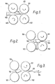
- Figs 1 to 3 show a pair of parallel contra-rotating squeeze rollers 101 and 102, preceded by a pair of contra-rotating pre-squeeze rollers 106,107, set at a wider nip distance, and illustrate the passage of a headed / ⁇ nd gutted fish carcass 103 between the rollers.
- Tail 104 of fish 103 is presented to the pre-squeeze rollers, and on being gripped between the rollers and thereby slightly pressed passes through in the direction indicated between the squeeze rollers 101,102.
- the bulk of fish 103 contacts the squeeze rollers it is squeezed between them and the flesh 105 within the fish is expressed therefrom (Fig 2).
- Fig 3 shows the final stage of the rolling procedure, with fish 103 (now comprising essentially merely the skin and backbone structure) having passed completely between the rollers and the flesh 105 remaining in front of the rollers.
- Fig 4 is a plan view showing the general lay-out of a fish processing apparatus according to the invention.
- the apparatus comprises a rectangular chamber 201, of which side walls 202 and 203 can be seen in section. Ends 204 and 205 of chamber 201 are open.
- a horizontal floor 206 spans the entire width of chamber 201, and extends slightly over half the length of the chamber from forward end 204.From the rear edge 207 of floor 206, a sloping chute 208 leads downwardly and outwardly from chamber 201. Chute 208 also spans the entire width of chamber 201.
- the apparatus is provided with a pair of parallel pre-squeeze rollers 209 and 210 mounted with their longitudinal axes vertical, the pair of rollers being adjacent the forward end 204 of chamber 201, and being symmetrically arranged on either side of the centre line AA running through chamber 201.
- a narrow gap 211 exists between the pair of pre-squeeze rollers.
- pre-squeeze rollers 209 and 210 Immediately behind pre-squeeze rollers 209 and 210 are a pair of squeeze rollers 212 and 213, again mounted with their longitudinal axes vertical and similarly symmetrically arranged on either side of centre line AA. Squeeze rollers 212 and 213 contact one another. The diameter of squeeze rollers 212 and 213 is less than that of the pre-squeeze rollers 209 and 210. Behind squeeze rollers 212 and 213 are mounted a pair of discharge rollers 214 and 215, again with their longitudinal axes vertical and also symmetrically arranged on either side of centre line AA. Rollers 214 and 215 are also in contact with one another, and their diameters are less than those of squeeze rollers 212 and 213.
- Each roller is rotatable about its longitudinal axes in a contrary manner relative to its partner, and in such a manner that an object presented from forward end 204 of chamber 1 between the pre-squeeze rollers 209 and 210 will be drawn into chamber 201 and progressed in turn between the three pairs of rollers towards rear end 205.
- a further pair of water pipes 218 and 219 lead into the apparatus and are directed via similar vertically-aligned V-jet spray heads against the rear of squeeze rollers 212 and 213.
- a third pair of water pipes 220 and 221 are similarly directed via similar spray heads against the rear of discharge rollers 214 and 215.
- a rectangular aperture 222 exists in floor 206, and lies symmetrically beneath the pre-squeeze rollers 209 and 210, and the squeeze rollers 212 and 213 such that anything falling between the two pairs of rollers will drop below floor 206.
- Leading edge 223 of floor 206 is provided with an up-turned lip 224 which runs the entire width of the shelf.
- Another up-turned lip 225 runs round the entire edge- of aperture 222.
- Side edges 226 and 227 of chute 208 are also provided with up-turned lips 228 and 229 respectively.
- Chute 230 which leads downwardly and outwardly from the front end 204 of chamber 201, commencing from the rear of aperture 222 such that anything falling through aperture 222 will land on chute 230 and be directed towards the front of the apparatus.
- Chute 230 is also provided with up-turned lips 231 and 232 along its side edges 233 and 234 respectively.
- the apparatus is also provided with a feeder mechanism 235 comprising an upper continuous belt 236 and a lower continuous belt 227 arranged in parallel one above the other along centre line AA at the forward end 204 of chamber 201.
- a feeder mechanism 235 comprising an upper continuous belt 236 and a lower continuous belt 227 arranged in parallel one above the other along centre line AA at the forward end 204 of chamber 201.
- Lower belt 236 extends further from the chamber than does the upper belt.
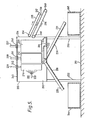
- rollers 209, 212 and 214 can be seen within chamber 201.
- Each roller is mounted on a vertical shaft 237, 238 and 239 respectivley, running through bearings 240, 241 and 242 respectively, situated in the roof 243 of chamber 201.
- the shafts are connected to a motor means (not shown) capable of causing rotation of each roller in the manner already described in relation to Fig 4.
- Water jet 220 playing onto the back of rollers 214 can also be seen.
- Floor 206 with aperture 222 and rim 225 can be seen, as also can the two sloping chutes 208 and 230.
- the sloping chutes are depicted as leading down to trays 244 and 245 respectively, capable of catching any material sliding down each chute.
- the two continuous belts 235 and 236 comprising the feeder mechanism can also be seen.
- Belt 235 runs round a pair of horizontally mounted rollers 246 and 247.
- Belt 236 runs round a similar pair of horizontally mounted rollers 248 and 249.
- the belts lead upwards into the open end 204 of chamber 201 adjacent the gap 211 between the pair of pre-squeeze rollers 209 and 210.
- a narrow gap 250 exists between the two belts along their entire adjacent length.
- the belts 235 ⁇ and 236 can be driven via their respective rollers by a motor means (not shown), such that they run in a contrary manner and any material placed between the belts will be drawn between them upwards into the apparatus.
- the whole apparatus is depicted as standing on ground 251 by means of legs mounted one at each corner, only the farther two of which legs (252 and 253) can be seen in this cross-section.
- the three pairs of rollers within the apparatus are set in rotational motion and the belts are also set running.
- Water is fed via the inlet pipes to the jets and played onto the rear of each roller.
- Headed and gutted but otherwise whole fish carcasses are fed tail first between the two belts, which convey the carcasses upwards into the gap 211 between the pre-squeeze rollers 209 and 210, which apply relatively gentle pressure to each fish carcass and soften up the muscle structure.
- the continuous rotation of the pre-squeeze rollers progresses the fish carcass towards the pair of squeeze rollers 212 and 213 which tightly grip the tail of the fish and draw the fish between them.
- the continuous jets of water played onto the rollers help in keeping each roller clean of fish flesh and slime from the fish skin, and thereby ensuring that the rollers maintain an adequate grip on each carcass and that the valuable fish flesh collected in tray 245 is not unduly contaminated with unwanted low-grade material.
- the water from each jet cascades down each roller onto floor 206 and then down rear chute 208.
- the up-turned lips 224 and 225 around the leading edge 223 of floor 206 and around aperture 222 help to prevent undue amounts of water becoming mixed with the valuable fish flesh.
- An additional or alternative means of ensuring that the fish flesh collected does not have an excessive water content is to use a foraminous material, such as an expanded metal screen, as the floor of the chute 230. Water can fall through the holes while the fish flesh slides down the chute into the waiting tray 245.
- a foraminous material such as an expanded metal screen
- the apparatus had the following technical specification.
- the pre-squeeze rollers were constructed of rubber having a hardness of 30 on the Shore scale, moulded onto 20 mm stainless steel shafts. Each roller had a length of 150 mm and a diameter of 90 mm. A textured surface, comprising a non-slip vinyl sheet material recommended for use as a deck covering for yachts, was bonded to each roller. A gap of 5 mm existed between the pre-squeeze rollers.
- the squeeze rollers were of identical construction to the pre-squeeze rollers, except that they had a diameter of 70 mm, and were just in contact with one another.
- the discharge rollers were constructed of rubber having a hardness of 35 on the Shore scale, moulded onto 15 mm diameter stainless steel shafts. Each roller had a length of 150 mm and a diameter of 40 mm. They were covered with the same non-slip material and were just in contact with one another.
Landscapes
- Life Sciences & Earth Sciences (AREA)
- Engineering & Computer Science (AREA)
- Wood Science & Technology (AREA)
- Zoology (AREA)
- Food Science & Technology (AREA)
- Processing Of Meat And Fish (AREA)
Applications Claiming Priority (2)
| Application Number | Priority Date | Filing Date | Title |
|---|---|---|---|
| GB8021724 | 1980-07-02 | ||
| GB8021724 | 1980-07-02 |
Publications (2)
| Publication Number | Publication Date |
|---|---|
| EP0043177A1 true EP0043177A1 (fr) | 1982-01-06 |
| EP0043177B1 EP0043177B1 (fr) | 1984-09-19 |
Family
ID=10514488
Family Applications (1)
| Application Number | Title | Priority Date | Filing Date |
|---|---|---|---|
| EP19810200751 Expired EP0043177B1 (fr) | 1980-07-02 | 1981-07-01 | Procédé et appareil pour enlever la chair du squelette de poissons |
Country Status (3)
| Country | Link |
|---|---|
| EP (1) | EP0043177B1 (fr) |
| DE (1) | DE3166173D1 (fr) |
| DK (1) | DK292981A (fr) |
Citations (6)
| Publication number | Priority date | Publication date | Assignee | Title |
|---|---|---|---|---|
| GB137027A (en) * | 1919-03-01 | 1919-12-31 | Nikolai Spjelkavik | A Machine for the Treatment of Herring and other Fish. |
| US1757013A (en) * | 1928-01-25 | 1930-05-06 | Bay State Fishing Company | Fish-filleting machine |
| US1793189A (en) * | 1929-12-16 | 1931-02-17 | Peters Anton | Apparatus for the recovery of meat from backbones of fishes |
| GB736013A (en) * | 1952-08-22 | 1955-08-31 | Samband Islenzkra Samvinnufela | Improvements in or relating to fish skinning machines |
| FR2007580A1 (fr) * | 1968-05-01 | 1970-01-09 | Bitterling Albert | |
| US3729775A (en) * | 1971-07-26 | 1973-05-01 | E Mcdonald | Apparatus for removing the skin from vertebrates such as fish & animals |
-
1981
- 1981-07-01 DK DK292981A patent/DK292981A/da not_active Application Discontinuation
- 1981-07-01 DE DE8181200751T patent/DE3166173D1/de not_active Expired
- 1981-07-01 EP EP19810200751 patent/EP0043177B1/fr not_active Expired
Patent Citations (6)
| Publication number | Priority date | Publication date | Assignee | Title |
|---|---|---|---|---|
| GB137027A (en) * | 1919-03-01 | 1919-12-31 | Nikolai Spjelkavik | A Machine for the Treatment of Herring and other Fish. |
| US1757013A (en) * | 1928-01-25 | 1930-05-06 | Bay State Fishing Company | Fish-filleting machine |
| US1793189A (en) * | 1929-12-16 | 1931-02-17 | Peters Anton | Apparatus for the recovery of meat from backbones of fishes |
| GB736013A (en) * | 1952-08-22 | 1955-08-31 | Samband Islenzkra Samvinnufela | Improvements in or relating to fish skinning machines |
| FR2007580A1 (fr) * | 1968-05-01 | 1970-01-09 | Bitterling Albert | |
| US3729775A (en) * | 1971-07-26 | 1973-05-01 | E Mcdonald | Apparatus for removing the skin from vertebrates such as fish & animals |
Also Published As
| Publication number | Publication date |
|---|---|
| DK292981A (da) | 1982-01-03 |
| EP0043177B1 (fr) | 1984-09-19 |
| DE3166173D1 (en) | 1984-10-25 |
Similar Documents
| Publication | Publication Date | Title |
|---|---|---|
| US4557017A (en) | Apparatus for filleting meat from poultry breast sections | |
| NO306042B1 (no) | Apparat for fjerning av hode og rensing av reker | |
| US4532677A (en) | Apparatus for opening and eviscerating scallops | |
| US3528124A (en) | Method of shucking shellfish | |
| US3662432A (en) | Apparatus for eviscerating scallops | |
| US4402112A (en) | Automatic poultry deboning apparatus | |
| US5106334A (en) | Machine for removing headbone, spine, gills and organs from a front part of a fish | |
| US5108342A (en) | High yield peeling means and method for uncooked warm-water shrimp | |
| US4481693A (en) | Method and apparatus for treating fish carcasses for separating flesh from frames and skins | |
| US3634909A (en) | Shrimp-peeling machine | |
| CA2088727C (fr) | Methode pour produire du poisson emince | |
| US3325856A (en) | Crab handling apparatus | |
| EP0043177B1 (fr) | Procédé et appareil pour enlever la chair du squelette de poissons | |
| KR20020031158A (ko) | 잘게 썬 어육제품 및 연육(어묵)을 위한 생선류의 제조방법 및 장치 | |
| CA1154209A (fr) | Methode et appareil pour enlever la chair des carcasses de poisson | |
| US3248752A (en) | Method for removing meat from animal carcasses | |
| JP3031708B2 (ja) | 甲殻類の尾から身を取り出す装置 | |
| JP3502835B2 (ja) | 皮剥機 | |
| US3683458A (en) | Apparatus for shucking shellfish | |
| EP0463701A1 (fr) | Dispositif à enlever la peau des doubles filets de poissons | |
| JPS5813343A (ja) | 魚肉を骨から剥す方法と装置 | |
| US4903373A (en) | Scallop eviscerating machine | |
| JP2554995B2 (ja) | 畜殺された家禽の体から皮を剥ぐ装置 | |
| US20250194615A1 (en) | Processing of Fish Products | |
| US3201822A (en) | Removal of meat from separated sections of the legs of king crab |
Legal Events
| Date | Code | Title | Description |
|---|---|---|---|
| PUAI | Public reference made under article 153(3) epc to a published international application that has entered the european phase |
Free format text: ORIGINAL CODE: 0009012 |
|
| 17P | Request for examination filed |
Effective date: 19810701 |
|
| AK | Designated contracting states |
Designated state(s): BE DE FR GB IT NL SE |
|
| RAP1 | Party data changed (applicant data changed or rights of an application transferred) |
Owner name: UNILEVER PLC Owner name: UNILEVER NV |
|
| ITF | It: translation for a ep patent filed | ||
| GRAA | (expected) grant |
Free format text: ORIGINAL CODE: 0009210 |
|
| AK | Designated contracting states |
Designated state(s): BE DE FR GB IT NL SE |
|
| REF | Corresponds to: |
Ref document number: 3166173 Country of ref document: DE Date of ref document: 19841025 |
|
| ET | Fr: translation filed | ||
| PG25 | Lapsed in a contracting state [announced via postgrant information from national office to epo] |
Ref country code: SE Effective date: 19850702 |
|
| PLBE | No opposition filed within time limit |
Free format text: ORIGINAL CODE: 0009261 |
|
| STAA | Information on the status of an ep patent application or granted ep patent |
Free format text: STATUS: NO OPPOSITION FILED WITHIN TIME LIMIT |
|
| PG25 | Lapsed in a contracting state [announced via postgrant information from national office to epo] |
Ref country code: BE Effective date: 19850731 |
|
| 26N | No opposition filed | ||
| BERE | Be: lapsed |
Owner name: UNILEVER N.V. Effective date: 19850731 |
|
| PG25 | Lapsed in a contracting state [announced via postgrant information from national office to epo] |
Ref country code: NL Effective date: 19860201 |
|
| GBPC | Gb: european patent ceased through non-payment of renewal fee | ||
| NLV4 | Nl: lapsed or anulled due to non-payment of the annual fee | ||
| PG25 | Lapsed in a contracting state [announced via postgrant information from national office to epo] |
Ref country code: FR Free format text: LAPSE BECAUSE OF NON-PAYMENT OF DUE FEES Effective date: 19860328 |
|
| PG25 | Lapsed in a contracting state [announced via postgrant information from national office to epo] |
Ref country code: DE Effective date: 19860402 |
|
| REG | Reference to a national code |
Ref country code: FR Ref legal event code: ST |
|
| PG25 | Lapsed in a contracting state [announced via postgrant information from national office to epo] |
Ref country code: GB Effective date: 19881118 |
|
| EUG | Se: european patent has lapsed |
Ref document number: 81200751.6 Effective date: 19860730 |