EP0043214B1 - Imprimante à disque - Google Patents
Imprimante à disque Download PDFInfo
- Publication number
- EP0043214B1 EP0043214B1 EP81302783A EP81302783A EP0043214B1 EP 0043214 B1 EP0043214 B1 EP 0043214B1 EP 81302783 A EP81302783 A EP 81302783A EP 81302783 A EP81302783 A EP 81302783A EP 0043214 B1 EP0043214 B1 EP 0043214B1
- Authority
- EP
- European Patent Office
- Prior art keywords
- type wheel
- shaft means
- hub
- shaft
- latch
- Prior art date
- Legal status (The legal status is an assumption and is not a legal conclusion. Google has not performed a legal analysis and makes no representation as to the accuracy of the status listed.)
- Expired
Links
- 230000008878 coupling Effects 0.000 claims description 3
- 238000010168 coupling process Methods 0.000 claims description 3
- 238000005859 coupling reaction Methods 0.000 claims description 3
- 230000006835 compression Effects 0.000 claims 1
- 238000007906 compression Methods 0.000 claims 1
- 230000007246 mechanism Effects 0.000 description 4
- 238000004519 manufacturing process Methods 0.000 description 2
- 238000000034 method Methods 0.000 description 2
- 230000008569 process Effects 0.000 description 2
- 230000000717 retained effect Effects 0.000 description 2
- 230000009471 action Effects 0.000 description 1
- 230000007547 defect Effects 0.000 description 1
- 238000010586 diagram Methods 0.000 description 1
- 230000006872 improvement Effects 0.000 description 1
- 239000000463 material Substances 0.000 description 1
- 239000011347 resin Substances 0.000 description 1
- 229920005989 resin Polymers 0.000 description 1
- 230000004044 response Effects 0.000 description 1
Images




Classifications
-
- B—PERFORMING OPERATIONS; TRANSPORTING
- B41—PRINTING; LINING MACHINES; TYPEWRITERS; STAMPS
- B41J—TYPEWRITERS; SELECTIVE PRINTING MECHANISMS, i.e. MECHANISMS PRINTING OTHERWISE THAN FROM A FORME; CORRECTION OF TYPOGRAPHICAL ERRORS
- B41J1/00—Typewriters or selective printing mechanisms characterised by the mounting, arrangement or disposition of the types or dies
- B41J1/22—Typewriters or selective printing mechanisms characterised by the mounting, arrangement or disposition of the types or dies with types or dies mounted on carriers rotatable for selection
- B41J1/24—Typewriters or selective printing mechanisms characterised by the mounting, arrangement or disposition of the types or dies with types or dies mounted on carriers rotatable for selection the plane of the type or die face being perpendicular to the axis of rotation
- B41J1/243—Mounting or fixing the carriers
-
- B—PERFORMING OPERATIONS; TRANSPORTING
- B41—PRINTING; LINING MACHINES; TYPEWRITERS; STAMPS
- B41J—TYPEWRITERS; SELECTIVE PRINTING MECHANISMS, i.e. MECHANISMS PRINTING OTHERWISE THAN FROM A FORME; CORRECTION OF TYPOGRAPHICAL ERRORS
- B41J25/00—Actions or mechanisms not otherwise provided for
- B41J25/24—Case-shift mechanisms; Fount-change arrangements
Definitions
- This invention relates to a printer or printing apparatus employing a daisy-type type wheel and, more particularly, to structure of the daisy-type type wheel and a mounting mechanism thereof.
- GB-A-2022022 discloses in Figure 9 a type wheel printer having axial latch means for latching the type wheel axially to a drive shaft and rotational latch means for latching the type wheel rotationally to the drive shaft.
- the type wheel is fitted in the printer by first mounting the type wheel in a zero position in a cassette, and mounting the cassette in the printer. It is then necessary to rotate the drive shaft into a zero position before coupling the type wheel rotationally to the shaft.
- GB-A-2031806 which shows an embodiment similar to the preamble of claim 1, discloses in Figure 1 a type wheel printer in which the type wheel is held in a zero position within a cartridge by a locking pin before the type wheel is coupled to the shaft, the locking pin being disengaged from the type wheel only when the drive shaft is rotated into a zero position and coupled to the type wheel.
- a type wheel printer comprising a carriage, a motor supported by the carriage, a rotatable shaft means driven by the motor, a type wheel having a hub, a plurality of spokes extending from said hub with a type supported at the free end of each of said plurality of spokes, said hub having a central opening engageable with said shaft means, said hub further having axial latch means for latching said type wheel axially to said shaft means when the end of said shaft means is inserted into said central opening in an axial direction, and rotational latch means for establishing a rotationally latched state wherein said type wheel is latched to said shaft means in the rotational direction of said shaft means characterized in that:
- a type wheel for use in a type wheel printer having a carriage, a motor supported by the carriage, rotatable shaft means driven by the motor and having an engaging portion radially spaced from the centre thereof, and stationary detent means, the type wheel having a hub, a plurality of spokes extending from said hub with a type supported at the free end of said plurality of spokes, said hub having a central opening engageable with said shaft means, said hub further having axial latch means for latching said type wheel axially to said shaft means when the end of said shaft means is inserted in said central opening in an axial direction, and rotational latch means for rotationally latching the type wheel to said shaft means, characterized in that said rotational latch means includes a latch member supported by said hub movably between a first position wherein said latch member engages with said engaging portion of the shaft means so as to rotationally latch the type wheel to the shaft means, and a second position wherein said latch member is not in engagement with said engaging portion, and resilient means biasing said latch
- a type wheel pulse motor 2 is recip- rocably supported in a perpendicular direction to the printing surface.
- This reciprocative movement of the pulse motor 2 in relation to the carriage is executed by a manual operation of a not-shown manual lever.
- a coupling member such as a drive element 4 is firmly fitted.
- the drive element 4 is, on the front end thereof, provided with a cylindrical portion 6 having a head portion 5 of substantially hexagonal shape in axial section and a flange 8 having an engaging recess such as a notch 7 on the periphery thereof, both being integrally formed.
- the drive element 4 and the motor shaft 2a constitute a rotary or drive shaft which is driven by the pulse motor 2.
- the cartridge holder 11 is constituted of a front wall 12 on the platen side (the side faces the platen 1 is called front in this embodiment), a rear wall 13 on the pulse motor side, side walls 14, and an under wall 15.
- the rear wall 13 is provided with a bend portion 16 engageable with an engaging portion 9b formed on the upper portion of the base plate 9 and an opening 17 for allowing the flange 8 to go into and come out of the cartridge holder 11.
- On the upper end of the front wall 12 a pair of engaging projections 18, which are illustrated not only in Fig. 1 but also in Fig. 5(A)-(C), are formed on either lateral side of the head portion 5 of the drive element 4 at a substantially same height with the center of the head portion 5.
- a spring 19 is disposed for biasing the cartridge holder 11 toward the base plate 9.
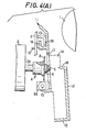
- the cartridge holder 11 when the pulse motor 2 is backwardly positioned, is postured rearwardly inclined as shown in Fig. 4(A) and (B) due to the biasing force of the spring 19, and uprightly positioned, after the forward movement of the pulse motor 2 by a manual operation in one direction of the manual lever, as shown in Fig. 4(C) and (D).
- the cartridge holder 11 By an operation of the manual lever in the reversed direction the cartridge holder 11 is moved back to the status shown in Fig. 4(A) and (B).
- a type wheel cartridge 20 accommodated in the cartridge holder 11, as shown in Fig. 3 and Fig. 5(A), is composed of a base plate 22 having a substantially circular recess 21 and a cover plate 23 covering the lower portion of the circular recess 21.
- a circular opening 23a is formed at a corresponding position to the central portion of the base plate 22, and an elongated elastic tongue 25 is so formed from the lower portion of the cover plate 23 as to reach at its upper free end the circular opening 23a.
- the tongue 25 is provided on the internal surface of its free end with a projection 26 of substantially conical shape.
- a daisy-type type wheel 27 accommodated in the type wheel cartridge 20 is provided with a hub 28 in the center and a multiplicity of spokes 30 with a type 29 on each end portion, being integrally formed of a resin material.
- a cap 31 is secured on the side of the platen 1 so as to function together with the hub 28 as a hub portion of the type wheel 27 itself.
- an opening or perforation 32 with an internal diameter almost equal to the external diameter of the cylindrical portion 6 of the drive element 4 is formed as a retaining bore, and in the central portion of the cap 31 a central opening or perforation 33 with an internal diameter slightly larger than the maximum external diameter of the head portion 5 of the cylindrical portion 6 is formed.
- a fastening member such as a wire spring 34 of substantially hair pin shape is mounted as shown in Fig. 5(A), and either arm portion thereof is so arranged as to cross the perforation 33 and the distance between the two is made larger than the diameter of the tip of the head portion 5 of the cylindrical portion 6 and smaller than the maximum diameter of the head portion 5 by a predetermined value, such that the maximum diametered portion of the head portion 5, when the head portion 5 advances between both arm portions, can pass therethrough due to forced expansion of the clearance between the both arm portions.
- Both arm portions pinch a neck portion between the head 5 and the cylindrical portion 6 to function as axial latch means for latching the drive shaft inserted into the perforation 32 and 33 in the axial direction thereof.
- a recess 35 is formed, and between the internal bottom surface thereof and the rear surface of the hub 28 a perforation 36 parallel to the cylindrical portion 6 is formed.
- the cap 31 is also provided with a recess 37 at a corresponding position to the recess 35, and between the internal bottom surface thereof and the front surface of the cap 31 a similar perforation 38 is formed.
- a pin 40 with a rib 39 is movably accommodated forwardly and backwardly, so that either the front end or the rear end thereof may be projected outside either one of the perforations 38, 36.
- the pin 40 is, by a resilient member such as a spring 41 supported between the inner surface of the hub 28 and the inner surface of the cap 31, backwardly biased so that the rib 39 is normally abutted on the inner surface of the hub 28 for making the rear end of the pin 40 pierce through the perforation 36 of the hub 28 as to protrude outside the hub 28 and the front end not protrude outside the cap 31.
- a resilient member such as a spring 41 supported between the inner surface of the hub 28 and the inner surface of the cap 31, backwardly biased so that the rib 39 is normally abutted on the inner surface of the hub 28 for making the rear end of the pin 40 pierce through the perforation 36 of the hub 28 as to protrude outside the hub 28 and the front end not protrude outside the cap 31.
- the projection 26 of the tongue 25 is fitted into the perforation 33 of the cap 31, as shown in Fig. 4(B), so as to fix the center of the type wheel 27 in relation to the type wheel cartridge 20 as well as free rotably retain the type wheel 27.
- This printer or printing apparatus is, as shown in Fig. 6, also provided with a control circuit 45 for rotating the pulse motor 2 more than one time in one direction in response to the closing operation of a cover 46 and a power switch 47 shown in Figs. 7 and 8.
- a cover switch 49 which is turned ON by a projection 51 upon closing of the cover 46.
- this cover switch 49 is, along with the power switch 47, connected to the control circuit 45 by way of the AND circuit 50.
- the pulse motor 2 is automatically rotated more than one time.
- “more than one time of rotation” includes rotation less than two times, e.g. one and a half, but in this embodiment the pulse motor 2 is rotated two times.
- the type wheel cartridge 20 accommodating the type wheel 27 of such structure is attached to the printer, the type wheel cartridge 20 is inserted into the cartridge holder 11 in a state shown in Fig. 4(A), with the tongue 25 positioned on the side of the platen 1 as shown in Fig. 4(B).
- the pulse motor 2 is subsequently moved forwardly by means of operation of the manual lever as shown in Fig.
- the head portion 5 and the cylindrical portion 6 begin to advance into the perforation 32 in the type wheel 27 through the opening 22c in the type wheel cartridge 20 in an inclined status, and the head portion 5 is contacted with the projection 26 of the tongue 25 for urging the same against the resilient force thereof to the side of the platen 1 so as to finally release the engagement of the projection 26 of the tongue 25 with the perforation 33 of the cap 31.
- the position of the notch 7 of the flange 8 coincides or being aligned with that of the pin 40 of the type wheel 27, the notch 7 and the pin 40 will be due to forward movement of the pulse motor 2 mutually fitted, for causing the drive element 4 and the type wheel 27 to be connected at a predetermined rotation directional position.
- the head portion 5 of the drive element 4 expands the clearance between both arm portions of the wire spring 34 so as to finish the engagement with the wire spring 34 by snap action, after having passed through at the maximum diametered portion thereof the clearance between both arm portions as shown in Fig. 4(D), for fitting into the perforation 33 of the cap 31.
- the cylindrical portion 6 is fitted into the perforation 32 of the hub 28 so as to complete the positioning in the axial direction of the drive element 4 and the type wheel 27.
- the drive element 4 begins in turn to rotate in one direction actuated by the rotation of the motor shaft 3.
- the drive element 4 and the type wheel 27 are rotated integrally in the beginning stage, in the range of 180° at maximum, but rotation of the type wheel 27 is suspended, as soon as the forwardly projected end out of the cap 31 of the pin 40 is engaged with one of the engaging projections 18 of the cartridge holder 11, leaving the drive element 4 to be further rotated alone.
- the notch 7 of the flange 8 and the pin 40 are aligned with each other, as shown in Fig.
- the rear end of the pin 40 is fitted into the notch 7 due to the biasing force of the spring 41 so that the front end of the pin 40 will be completely sunk within the cap 31.
- the type wheel 27 and the drive element 4 are therefore connected at a predetermined relative position in the rotational direction, as shown in Fig. 1, releasing the engagement between the engaging projections 18 and the pin 40.
- the drive element 4 and the type wheel 27 are to be rotated in unison through a pin engagement between the two.
- the drive element 4 will later be halted after having rotated twice from the starting.
- the type wheel 27 is placed therefore in a freely rotatable condition relative to the type wheel cartridge 20 and the cartridge holder 11, and afterwards rotated together with the drive element 4 by the later rotation of the pulse motor 2 for allowing suitable type selecting operation of the type wheel 27.
Landscapes
- Accessory Devices And Overall Control Thereof (AREA)
- Character Spaces And Line Spaces In Printers (AREA)
Claims (13)
Applications Claiming Priority (4)
| Application Number | Priority Date | Filing Date | Title |
|---|---|---|---|
| JP8934780A JPS5751469A (en) | 1980-06-30 | 1980-06-30 | Printer |
| JP8934680A JPS5714048A (en) | 1980-06-30 | 1980-06-30 | Petal type type wheel |
| JP89347/80 | 1980-06-30 | ||
| JP89346/80 | 1980-06-30 |
Publications (3)
| Publication Number | Publication Date |
|---|---|
| EP0043214A2 EP0043214A2 (fr) | 1982-01-06 |
| EP0043214A3 EP0043214A3 (en) | 1982-12-15 |
| EP0043214B1 true EP0043214B1 (fr) | 1986-05-14 |
Family
ID=26430766
Family Applications (1)
| Application Number | Title | Priority Date | Filing Date |
|---|---|---|---|
| EP81302783A Expired EP0043214B1 (fr) | 1980-06-30 | 1981-06-19 | Imprimante à disque |
Country Status (4)
| Country | Link |
|---|---|
| US (1) | US4389129A (fr) |
| EP (1) | EP0043214B1 (fr) |
| CA (1) | CA1174632A (fr) |
| DE (1) | DE3174618D1 (fr) |
Families Citing this family (20)
| Publication number | Priority date | Publication date | Assignee | Title |
|---|---|---|---|---|
| DE3207206A1 (de) * | 1982-02-27 | 1983-09-08 | Olympia Werke Ag, 2940 Wilhelmshaven | Druckwerk fuer eine schreib- oder aehnliche bueromaschine mit einer aufnahmevorrichtung fuer eine wechselkassette mit einem typenrad |
| DE3211402A1 (de) * | 1982-03-27 | 1983-09-29 | Olympia Werke Ag, 2940 Wilhelmshaven | Druckwerk fuer eine schreib- oder aehnliche bueromaschine |
| JPS58211476A (ja) * | 1982-06-02 | 1983-12-08 | Canon Inc | 電子印字装置 |
| GB2135246B (en) * | 1983-02-23 | 1987-05-13 | Ricoh Kk | Daisy wheel supporting structure |
| IT1158811B (it) * | 1983-02-28 | 1987-02-25 | Olivetti & Co Spa | Dispositivo per accoppiare un disco portacaratteri ad un motore di selezione |
| IT1159366B (it) * | 1983-03-10 | 1987-02-25 | Olivetti & Co Spa | Dispositivo per montare un disco portacaratteri in una macchina per scrivere |
| DE3314867A1 (de) * | 1983-04-25 | 1984-10-25 | Olympia Werke Ag, 2940 Wilhelmshaven | Druckwerk fuer eine schreib- oder aehnliche bueromaschine |
| DE3322999A1 (de) * | 1983-06-25 | 1985-01-03 | Olympia Werke Ag, 2940 Wilhelmshaven | Druckwerk fuer eine schreib- oder aehnliche bueromaschine |
| EP0168486A1 (fr) * | 1984-01-16 | 1986-01-22 | LAHR, Roy Jeremy | Element d'impression rotatif, ses composants et appareil de couplage d'entrainement pour celui-ci |
| US4582438A (en) * | 1984-02-29 | 1986-04-15 | Tokyo Juki Industrial Co., Ltd. | Type wheel-type selector motor coupling detection device in printer |
| DE3508330A1 (de) * | 1984-03-09 | 1985-09-19 | Ricoh Co., Ltd., Tokio/Tokyo | Typenradkassette fuer eine druckeinrichtung |
| US4613244A (en) * | 1984-04-13 | 1986-09-23 | Tokyo Juki Industrial Co., Ltd. | Device for mounting printing type array on printer |
| US5203636A (en) * | 1984-11-12 | 1993-04-20 | Canon Kabushiki Kaisha | Printing apparatus capable of distinguishing functioning abnormalities |
| JPS625874A (ja) * | 1985-07-01 | 1987-01-12 | Brother Ind Ltd | 印字装置 |
| US4686900A (en) * | 1985-12-05 | 1987-08-18 | Xerox Corporation | Impact printer with application of oblique print force |
| DE3606545C1 (de) * | 1986-02-28 | 1987-04-16 | Triumph Adler Ag | Vorrichtung zum Kuppeln eines Typenrades mit einer Dreheinstellwelle in Schreib- oder aehnlichen Maschinen |
| CH668039A5 (fr) * | 1986-04-16 | 1988-11-30 | Caracteres Sa | Disque porte-caracteres pour machine imprimante. |
| US4768891A (en) * | 1986-10-15 | 1988-09-06 | Smith Corona Corporation | Typewriter lid actuated printing element homing and carrier reposition device |
| JPH01137231U (fr) * | 1988-03-05 | 1989-09-20 | ||
| JP2638972B2 (ja) * | 1988-08-16 | 1997-08-06 | ブラザー工業株式会社 | プリンタ |
Family Cites Families (11)
| Publication number | Priority date | Publication date | Assignee | Title |
|---|---|---|---|---|
| IT986534B (it) * | 1973-06-19 | 1975-01-30 | Olivetti & Co Spa | Dispositivo di scrittura in serie con disco portacaratteri alamine flessibili |
| US3878929A (en) * | 1973-11-23 | 1975-04-22 | Pitney Bowes Inc | Type disc with integral coupling device |
| US4049110A (en) * | 1976-05-28 | 1977-09-20 | Xerox Corporation | Print wheel mounting assembly |
| DE2822313C2 (de) * | 1978-05-22 | 1985-07-04 | Olympia Werke Ag, 2940 Wilhelmshaven | Typenradkassette für Schreib- oder ähnliche Büromaschinen |
| JPS6054186B2 (ja) * | 1978-09-18 | 1985-11-29 | 株式会社リコー | 印字装置 |
| GB2031806B (en) * | 1978-09-18 | 1983-06-29 | Nippon Tsushin Gijutsu Kk | Impact printer |
| US4245916A (en) * | 1978-12-11 | 1981-01-20 | International Business Machines Corporation | Daisy wheel print element structured for use in a cartridge |
| CH627687A5 (fr) * | 1978-12-20 | 1982-01-29 | Hermes Precisa International | Dispositif de mise en place et de fixation d'un disque d'impression. |
| SE425958B (sv) * | 1979-01-12 | 1982-11-29 | Facit Ab | Anordning for att vid tryckverk vid elektriska kontorsmaskiner losbart forbinda ett typelement med en motoraxel |
| DE2902544C2 (de) * | 1979-01-24 | 1984-05-17 | Olympia Werke Ag, 2940 Wilhelmshaven | Aufnahmevorrichtung für Typenscheiben in Schreib oder ähnlichen Büromaschinen |
| US4264220A (en) * | 1979-12-12 | 1981-04-28 | International Business Machines Corporation | Printwheel homing apparatus |
-
1981
- 1981-06-18 US US06/275,013 patent/US4389129A/en not_active Expired - Fee Related
- 1981-06-19 EP EP81302783A patent/EP0043214B1/fr not_active Expired
- 1981-06-19 DE DE8181302783T patent/DE3174618D1/de not_active Expired
- 1981-06-29 CA CA000380849A patent/CA1174632A/fr not_active Expired
Non-Patent Citations (1)
| Title |
|---|
| XEROX DISCLOSURE JOURNAL, vol.4, no.1, January/February 1979 A.H. EDSTROM et al.: "Daisy print wheel retainer", pages 23-24 * |
Also Published As
| Publication number | Publication date |
|---|---|
| US4389129A (en) | 1983-06-21 |
| EP0043214A3 (en) | 1982-12-15 |
| CA1174632A (fr) | 1984-09-18 |
| DE3174618D1 (en) | 1986-06-19 |
| EP0043214A2 (fr) | 1982-01-06 |
Similar Documents
| Publication | Publication Date | Title |
|---|---|---|
| CA1174632A (fr) | Imprimante a tete en forme de roue | |
| US4127335A (en) | Impact printer with cartridge print wheel | |
| US4310255A (en) | Printer with cartridge type wheel | |
| US4771619A (en) | Steering lock device | |
| JPS6235169Y2 (fr) | ||
| US4324496A (en) | Type disc printer | |
| JPH0480835B2 (fr) | ||
| JPH0156914B2 (fr) | ||
| US5038236A (en) | Magnetic tape cassette ejecting device | |
| US6201660B1 (en) | Magnetic recording/reproducing apparatus | |
| JPS6132986B2 (fr) | ||
| JPS6144070B2 (fr) | ||
| KR900002238B1 (ko) | 차제용 카셋트식 테이프 레코더 | |
| JPH0319085Y2 (fr) | ||
| JPS5928468B2 (ja) | 印字ホイ−ルカセットを使用するプリンタ | |
| JPH056593Y2 (fr) | ||
| JPH028760Y2 (fr) | ||
| JPS5928469B2 (ja) | タイプライタの活字ホイ−ル装着装置 | |
| KR890006619Y1 (ko) | 비디오 카세트 레코더의 릴 브레이크 장치 | |
| JPS6132988B2 (fr) | ||
| KR920009046Y1 (ko) | 오토리버스 카데크용 이젝트 장치 | |
| KR920006377Y1 (ko) | 비디오 테이프 레코오더의 카세트 안전삽입 장착장치 | |
| JPH0567425B2 (fr) | ||
| JPH056585Y2 (fr) | ||
| KR930001366Y1 (ko) | 카메라 일체형 vtr의 하우징 이젝트 안전장치 |
Legal Events
| Date | Code | Title | Description |
|---|---|---|---|
| PUAI | Public reference made under article 153(3) epc to a published international application that has entered the european phase |
Free format text: ORIGINAL CODE: 0009012 |
|
| AK | Designated contracting states |
Designated state(s): DE FR GB IT |
|
| PUAL | Search report despatched |
Free format text: ORIGINAL CODE: 0009013 |
|
| AK | Designated contracting states |
Designated state(s): DE FR GB IT |
|
| 17P | Request for examination filed |
Effective date: 19830128 |
|
| GRAA | (expected) grant |
Free format text: ORIGINAL CODE: 0009210 |
|
| AK | Designated contracting states |
Kind code of ref document: B1 Designated state(s): DE FR GB IT |
|
| REF | Corresponds to: |
Ref document number: 3174618 Country of ref document: DE Date of ref document: 19860619 |
|
| ET | Fr: translation filed | ||
| ITF | It: translation for a ep patent filed | ||
| PLBE | No opposition filed within time limit |
Free format text: ORIGINAL CODE: 0009261 |
|
| STAA | Information on the status of an ep patent application or granted ep patent |
Free format text: STATUS: NO OPPOSITION FILED WITHIN TIME LIMIT |
|
| 26N | No opposition filed | ||
| ITTA | It: last paid annual fee | ||
| PGFP | Annual fee paid to national office [announced via postgrant information from national office to epo] |
Ref country code: FR Payment date: 19920609 Year of fee payment: 12 |
|
| PG25 | Lapsed in a contracting state [announced via postgrant information from national office to epo] |
Ref country code: FR Effective date: 19940228 |
|
| REG | Reference to a national code |
Ref country code: FR Ref legal event code: ST |
|
| PGFP | Annual fee paid to national office [announced via postgrant information from national office to epo] |
Ref country code: GB Payment date: 19950608 Year of fee payment: 15 |
|
| PGFP | Annual fee paid to national office [announced via postgrant information from national office to epo] |
Ref country code: DE Payment date: 19950617 Year of fee payment: 15 |
|
| PG25 | Lapsed in a contracting state [announced via postgrant information from national office to epo] |
Ref country code: GB Effective date: 19960619 |
|
| GBPC | Gb: european patent ceased through non-payment of renewal fee |
Effective date: 19960619 |
|
| PG25 | Lapsed in a contracting state [announced via postgrant information from national office to epo] |
Ref country code: DE Effective date: 19970301 |