EP0043268A1 - Leiterhalter für Fahrzeuge - Google Patents
Leiterhalter für Fahrzeuge Download PDFInfo
- Publication number
- EP0043268A1 EP0043268A1 EP81302929A EP81302929A EP0043268A1 EP 0043268 A1 EP0043268 A1 EP 0043268A1 EP 81302929 A EP81302929 A EP 81302929A EP 81302929 A EP81302929 A EP 81302929A EP 0043268 A1 EP0043268 A1 EP 0043268A1
- Authority
- EP
- European Patent Office
- Prior art keywords
- ladder
- handle
- support assembly
- retaining member
- roller
- Prior art date
- Legal status (The legal status is an assumption and is not a legal conclusion. Google has not performed a legal analysis and makes no representation as to the accuracy of the status listed.)
- Granted
Links
- 230000000712 assembly Effects 0.000 claims abstract description 15
- 238000000429 assembly Methods 0.000 claims abstract description 15
- 230000000694 effects Effects 0.000 claims description 4
- 229910001209 Low-carbon steel Inorganic materials 0.000 description 3
- 238000010276 construction Methods 0.000 description 2
- 239000002184 metal Substances 0.000 description 2
- 229920001875 Ebonite Polymers 0.000 description 1
- 229910000831 Steel Inorganic materials 0.000 description 1
- 230000004308 accommodation Effects 0.000 description 1
- 230000006835 compression Effects 0.000 description 1
- 238000007906 compression Methods 0.000 description 1
- 239000000463 material Substances 0.000 description 1
- 230000001681 protective effect Effects 0.000 description 1
- 239000010959 steel Substances 0.000 description 1
Images




Classifications
-
- B—PERFORMING OPERATIONS; TRANSPORTING
- B60—VEHICLES IN GENERAL
- B60R—VEHICLES, VEHICLE FITTINGS, OR VEHICLE PARTS, NOT OTHERWISE PROVIDED FOR
- B60R9/00—Supplementary fittings on vehicle exterior for carrying loads, e.g. luggage, sports gear or the like
- B60R9/04—Carriers associated with vehicle roof
- B60R9/048—Carriers characterised by article-gripping, -covering,-retaining, or -locking means
- B60R9/0485—Carriers characterised by article-gripping, -covering,-retaining, or -locking means for ladders
Definitions
- This invention relates to a vehicle roof rack, in particular to a vehicle roof rack adapted for the transportation of ladders.
- the present invention provides a ladder rack for a vehicle roof comprising a sub-frame having means for releasable attachment to the roof of a vehicle, and front and rear ladder support assemblies mounted on the sub-frame, each support assembly comprising at least one transverse roller for engaging the stringers of a ladder spanning the two assemblies, and at least one support assembly further comprising at least one ladder-retaining member pivotable about a transverse axis from a lowered inoperative position to araised operative position wherein the said member engages a rung of a ladder spanning the two assemblies, the rear assembly further comprising a handle pivotally mounted at one side thereof which is coupled to the ladder-retaining member to effect the said raising and lowering of the latter.
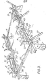
- a ladder rack for a vehicle roof comprises a sub-frame of rectangular form comprising longitudinal side members 5 rigidly secured to transverse cross-members 6.
- the sub-frame comprises four clamps 7 by which the sub-frame is releasably attached to a vehicle roof in conventional manner.
- This is shown in Figure 12 for the third embodiment to be described below - however the sub-frame is substantially the same for each embodiment and the manner of fixing to the vehicle roof is the same.
- a pair of front ladder support assemblies 8 are mounted on the front cross-member 6 of the sub-frame, and a pair of rear ladder support assemblies 9 are mounted on the rear cross-member.
- Each front assembly 8 is longitudinally aligned with a respective rear assembly 9 and together with the latter forms a support for a single ladder spanning the two assemblies.
- the embodiment illustrated provides accommodation for two ladders side-by-side; however this is not essential and if desired a single front assembly 8 and a single rear assembly 9 may be provided. Since each pair of assemblies 8 and 9 are of identical construction only the rearside pair will be described in detail in this and the succeeding embodiments.
- the front support assembly 8 comprises a mild steel frame 10 which rotatably carries a transverse shaft 11 upon which are freely mounted two roller arms 12; and 13. The latter in turn have a transverse shaft 14 mounted between the free ends thereof, the shaft 14 carrying rollers 15 and 16.
- the shaft 11 has rigidly secured thereon two ladder-retaining bars 19 and 20.
- the rear support assembly 9 similarly has a mild steel frame 21 rotatably carrying a transverse shaft 22 with roller arms 23 and 24 which carry rollers 25 and 25.
- the roller arms 23,24 are fixed rigidly to the base of the frame 21 with the shaft 22 passing freely through them, and each roller 25 and 26 is rotatably mounted between one end of the frame 21 and a respective arm 23 and 24.
- the shaft 22 also has rigidly secured thereto two ladder-retaining bars 27 and 28.
- the rear assembly 9 carries on one side thereof a first handle 31 which is pivotally mounted on a bracket plate 32 secured to the frame 21 (see Figs. 3 and 5).
- the handle 31 pivots about the point 33 and has a stop plate 34 also secured to the frame 21.
- Intermediate the length of the handle 31 is pivotally connected a rod 35 which passes at its other end through a housing 36 provided with a spring 37, the rod 35 being secured by a lock nut 38.
- the housing 36 is pivotally secured between two plates 39, which are in turn rigidly secured to the roller arm 12 of the front assembly 8.
- a clockwise depression of the handle 31 to engage the stop plate 34 causes the rod 35 to be pulled rearward imparting, through the housing 36 and the plates 39, an anti-clockwise pivital movement to the roller arm 12 to raise the rollers 15 and 16 to an elevated position.
- the handle is overcentre and is thus held locked in position by the spring 37.
- the rollers 25 and 26 of the rear rack are not.connected to the lifting handle 31 and are not adapted to be raised.
- the rear assembly 9 is also provided with a second handle 40, on the opposite side to the handle 31, and this handle 40 is operatively associated with the bars 19, 20,27 and 28 (see figs. 1 and 4).
- The/handle 40 is pivotally mounted at 41 to a bracket 42 secured to the frame 21 and has a stop plate 43 also secured to the frame 21.
- a rod 44 which passes through a housing 45 having a spring 46 bearing against a locknut 47 which retains the rod 44 in position.
- the housing 45 is pivotally mounted between two plates 48 which are rigidly secured to the shaft 22 between the bracket 42 and a further bracket 49 secured to the frame 21.
- the plates 48 are rigidly secured to a second plate 50 - the longitudinal axes of the plates 48, 50 defining a contained angle of 60°.
- the plate 50 has pivotally connected to the free end thereof a rod 51 which, in a similar manner as the rod 35, is connected to two plates 52 through a housing 53 with a spring 54 and a lock nut 55 for securing the connection of the rod 51.
- the plates 52 are rigidly secured to the shaft 11 of the front assembly.
- the handle 40 is pulled down to engage the stop plate 43, which causes the rod 44 to rotate the plates 48 and 50 to directly pivot the bars 27, 28 into an upright operative position and, indirectly through the rod 51, housing 53 and plates 52, pivot the bars 19, 20 also into an upright operative position.
- the handle 40 engages the stope plate 43 the handle is overcentre and is held in this locked position under the influence of a spring 56 connected at 57 to the rod 44 and to the outer one of the plates 48.
- the above ladder rack operates as follows.
- the rollers 15 and 16 are in the lowered position, at substantially the same level as the fixed rollers 25 and 26, and all four ladder-retaining bars 19, 20, 27 and 28 are in their lowered inoperative positions.
- a ladder is run along the rollers 15, 16,25, 26 from the rear, the rollers engaging the stringers (uprights) of the ladder.
- the handle 40 is pulled down to raise the bars .19, 20, 27 and 28 simultaneously to the upright position between rungs of the ladder to engage the said rungs and thereby lock the ladder into position on the roof rack ( Figure 2). Since the rung spacing will not in general be the same as the spacing between the front and rear pairs of ladder-retaining bars the latter resiliently press in opposite directions on the rungs by compression of the springs 46 and 54.
- the materials used in the construction of the roof rack are preferably mild steel for all metal parts and for the rollers preferably a hard rubber outer surface on a steel sleeve.
- the metal components of the roof rack are preferably painted to match the colour scheme of the vehicle e.g. the van, with which the roof rack is used.
- FIG. 6 A second embodiment of the invention is shown in Figures 6 and 7, in which the same reference numerals have been used for components which perform the same or a similar function as components of the first embodiment.
- the handle 40 (which has now been moved to the rearside of the/rear assembly 9) operates only on the shaft 22 to raise and lower a single hook-form ladder-retaining plate 27 rigidly secured thereto, so that the components 50 to 55 of the first embodiment are omitted, and secondly that the handle 31 (which has been moved to the offside of the rear assembly) operates not only to raise and lower the rollers 15 and 16 but also operates to raise and lower a single right-angle ladder-retaining bar 19 welded to the shaft 11, the bar 19 being raised when the rollers 15 and 16 are lowered and vice versa.
- the rollers 25 and 26 of the rear assembly 9 are now freely mounted directly on the shaft 22 on opposite sides of the single hook-form plate 27 which is bolted to the shaft 22 as shown.
- the handle 40 is of right-angle design for compactness and does not engage the stop plate 43 directly. Instead, the stop function is performed by a plate 60 welded to the rod 44, the plate 43 and 60 having co-operating holes 61 for a padlock.
- the plates 48 are rigidly secured to the shaft 22, but the spring 56 is connected between the rod 44 and the sub-frame rather than between the rod 44 and outer plate 48.
- the overcentering action is the same with the handle 40 being locked in the down position (figure 11).
- the hook shape of the plate 27 is designed to give clearance over a rung of the ladder when the handle 40 is pushed down, and in the final part of its motion to actually hook over the rung and grip the latter. Since this design does not depend upon a resilient pressure against the rung to retain the ladder in position the spring 46 of the first embodiment is omitted and the rod 44 is held at a fixed position in the housing 45 by two nuts 62 on opposite sides thereof.
- the rear support assembly is also provided with a protective bumper 63 which protects the rear/of the vehicle when a ladder is being loaded or unloaded - see also Figure 12.
- the roller support arms 12 and 13 are rigidly secured to the shaft 11 so that the right-angle bar 19, the arms 12 and 13, and the rollers 15 and 16 on their shaft 14 form a single rigid assembly pivotting about the axis of the shaft 11. Such pivotting is effected, as before, by a handle 31 via a connecting rod 35.
- the front assembly comprises a second pair of rollers 64,65 freely mounted on the shaft 11, similar to the rollers 25 and 26 on the shaft 22.
- Figure 6 shows the unlocked position of the roof rack for the loading and unloading of a ladder.
- the handle 40 is in the upper position so that the plate 27 is in its lowered inoperative position.
- the handle 31, on the other hand, is in its lower position so that the front rollers 15 and 16 are raised about the level of the bar 19 which is thus in its lowered inoperative position.
- a ladder may now be run onto the assemblies from the rear, running on the rollers 25,26 and 15,16.
- To lock the ladder in position the handle 40 is pulled down and the handle 31 pushed up ( Figure 7).
- the hooked plate 27 is raised to its operative position and thereby engages over a rung of the ladder, and the rollers 15 and 16 are lowered to bring the front bar 19 into its raised operative position between two adjacent rungs of the ladder with the free end of the bar extending over one of the rungs. In this position the front end of the ladder rests on the rollers 64 and 65.
- FIGs 8 and 9 show the locked and unlocked , positions of a third embodiment of the invention.
- This third embodiment is basically a simplified version of the second embodiment of Figures 6 and 7, and similar reference numerals have been used for similar parts.
- the simplification consists in the fact that the front assembly 8 comprises only the pair of fixed rollers 64,65 mounted on the shaft 11, the bar 18, the roller support arms 12 and 13, and the rollers'15 and 16 on their shaft 14 all being omitted. Consequently the handle 31 and rod 35 are unnecessary, there now being no connection between the front and rear assemblies.
- the operation of the rear assembly 9 is however identical to that described in relation to the second embodiment, in particular as shown in Figures 10 and 11. It is to be noted that in the third embodiment the only ladder-retaining means is the single hooked plate 27 of the rear. assembly 9.
- each pair of rollers on the same shaft such as the rollers 15 and 16 on the shaft 14, may be replaced by a single roller extending along substantially the entire length of the shaft.
Landscapes
- Engineering & Computer Science (AREA)
- Mechanical Engineering (AREA)
- Vehicle Step Arrangements And Article Storage (AREA)
- Fittings On The Vehicle Exterior For Carrying Loads, And Devices For Holding Or Mounting Articles (AREA)
- Ladders (AREA)
Priority Applications (1)
| Application Number | Priority Date | Filing Date | Title |
|---|---|---|---|
| AT81302929T ATE10463T1 (de) | 1980-06-30 | 1981-06-29 | Leiterhalter fuer fahrzeuge. |
Applications Claiming Priority (4)
| Application Number | Priority Date | Filing Date | Title |
|---|---|---|---|
| IE1375/80A IE49850B1 (en) | 1980-06-30 | 1980-06-30 | Ladder rack for vehicle |
| IE137580 | 1980-06-30 | ||
| IE68381 | 1981-03-26 | ||
| IE68381 | 1981-03-26 |
Publications (2)
| Publication Number | Publication Date |
|---|---|
| EP0043268A1 true EP0043268A1 (de) | 1982-01-06 |
| EP0043268B1 EP0043268B1 (de) | 1984-11-28 |
Family
ID=26318949
Family Applications (1)
| Application Number | Title | Priority Date | Filing Date |
|---|---|---|---|
| EP81302929A Expired EP0043268B1 (de) | 1980-06-30 | 1981-06-29 | Leiterhalter für Fahrzeuge |
Country Status (6)
| Country | Link |
|---|---|
| US (1) | US4390117A (de) |
| EP (1) | EP0043268B1 (de) |
| CA (1) | CA1171397A (de) |
| DE (1) | DE3167439D1 (de) |
| DK (1) | DK287781A (de) |
| IE (1) | IE49850B1 (de) |
Cited By (2)
| Publication number | Priority date | Publication date | Assignee | Title |
|---|---|---|---|---|
| FR2632040A1 (fr) * | 1988-05-30 | 1989-12-01 | Caetano Bosq Sarl | Dispositif de verrouillage d'echelle pour porte-echelle monte sur un vehicule utilitaire ou autre |
| AU777416B2 (en) * | 2000-11-10 | 2004-10-14 | Rhino Rack Australia Pty Limited | Ladder rail and ladder pad arrangement |
Families Citing this family (47)
| Publication number | Priority date | Publication date | Assignee | Title |
|---|---|---|---|---|
| US4827742A (en) * | 1986-02-04 | 1989-05-09 | Unistrut Australia Pty. Ltd. | Security assembly for vehicle roofrack |
| US4751981A (en) * | 1987-10-02 | 1988-06-21 | Mitchell John C | Detachably mounted ladder rack |
| US4923103A (en) * | 1989-06-29 | 1990-05-08 | Sauber Charles J | Ladder rack |
| US5058791A (en) * | 1990-02-09 | 1991-10-22 | Slide-Out, Inc. | Vehicular ladder rack |
| US5137194A (en) * | 1990-12-08 | 1992-08-11 | U S West Business Resources, Inc. | Ladder support rack |
| US5454612A (en) * | 1991-09-19 | 1995-10-03 | Christensen; David | Pick-up truck rail with anchor slots |
| US5137320A (en) * | 1991-09-19 | 1992-08-11 | David Christensen | Ladder utility rack and mounting rail |
| US5393114A (en) * | 1991-09-19 | 1995-02-28 | Christensen; David | Reversible utility rail and utility rack |
| US5470120A (en) * | 1991-09-19 | 1995-11-28 | Christensen; David | Base rail for utility rack |
| US5238280A (en) * | 1991-09-19 | 1993-08-24 | David Christensen | Utility rack with enhanced rails |
| US5255832A (en) * | 1991-12-04 | 1993-10-26 | David Christensen | Universal equipment mounts, enclosed mounts and mounting rails |
| US5242094A (en) * | 1992-04-27 | 1993-09-07 | Finley Alfred L | Ladder rack |
| USD346994S (en) | 1992-07-30 | 1994-05-17 | Knaack Manufacturing Company | Ladder rack support |
| US5269417A (en) * | 1992-07-30 | 1993-12-14 | Zelnik David D | Method and assembly for storing a dolly bar |
| US5996736A (en) * | 1998-03-11 | 1999-12-07 | Danny Stankiewicz | Ladder locking device |
| US6179543B1 (en) | 1998-05-21 | 2001-01-30 | Dennis Adame | Rack for motor vehicles |
| US6257534B1 (en) * | 1999-03-02 | 2001-07-10 | Fibre Body Industries Inc | Ladder rack assembly |
| US6378654B1 (en) | 2000-07-18 | 2002-04-30 | Theodore Ziaylek, Jr. | Ladder pivotally attached to a generally vertically extending surface |
| US6688428B2 (en) * | 2001-08-17 | 2004-02-10 | Elmer C. Carroll, Jr. | Universal ladder lock and method |
| US6736300B2 (en) | 2002-03-19 | 2004-05-18 | Ray Deakin | Vehicle roof rack kit |
| US6929162B1 (en) * | 2002-05-13 | 2005-08-16 | Lawrence R Jordan | Automatic locking ladder rack |
| US6854627B2 (en) * | 2002-08-09 | 2005-02-15 | Erack Llc | Vehicular utility rack |
| US20040047716A1 (en) * | 2002-09-05 | 2004-03-11 | L&P Property Management Company | Ladder rack apparatus and method |
| GB2399074B (en) * | 2003-03-05 | 2005-05-18 | Brightwell Dispensers Ltd | Soap dispensing device |
| US6827541B1 (en) | 2003-04-15 | 2004-12-07 | Michael Paul Ziaylek | Apparatus for holding elongated objects horizontally adjacent to a vehicular body which is movable between an upper storage position and a lower access position |
| US7258260B2 (en) * | 2003-08-29 | 2007-08-21 | Hurd Jonathan H | Cargo system attachable to a roof rack |
| US7097409B2 (en) | 2003-10-14 | 2006-08-29 | Adrian Steel Co. | Ladder rack system |
| US7210559B2 (en) * | 2004-04-28 | 2007-05-01 | Cross Tread Industries, Inc. | Apparatus and method for holding/locking a ladder or other object to a structure |
| US20060000860A1 (en) * | 2004-06-30 | 2006-01-05 | Pieciak Kenneth F | Rack mount assembly for vehicle roof racks |
| US7845597B2 (en) * | 2005-11-17 | 2010-12-07 | Scott Gatta | Conduit carrier system |
| US20070183875A1 (en) * | 2006-02-09 | 2007-08-09 | Paul Thibault | Ladder rack system |
| US7992682B2 (en) | 2007-12-21 | 2011-08-09 | Michael Paul Ziaylek | Ladder storing apparatus for use with an emergency vehicle |
| WO2009140496A2 (en) * | 2008-05-14 | 2009-11-19 | Frank Elezaj | Vehicle roof storage system |
| US20110214944A1 (en) * | 2010-03-08 | 2011-09-08 | Levi Avraham Y | Ladder Clamping Structure for Ladder Racks |
| US8925776B2 (en) | 2011-11-30 | 2015-01-06 | Kevin Moore | Device and method for transporting elongate objects using a pick-up truck |
| US20130193176A1 (en) * | 2012-02-01 | 2013-08-01 | Denis Khoo | Securing Apparatus for a Roof Rack |
| US8511525B1 (en) * | 2012-02-06 | 2013-08-20 | Avraham Y. Levi | Roller guide for vehicle roof mounted ladder rack |
| US8985933B2 (en) | 2012-06-05 | 2015-03-24 | Michael P. Ziaylek | Remote equipment storage apparatus with a downwardly extendable retrieval position |
| USD729142S1 (en) | 2013-05-10 | 2015-05-12 | Michael P. Ziaylek | Remote equipment storage apparatus for an emergency vehicle |
| AU2016340033B2 (en) * | 2015-10-14 | 2021-09-02 | Kracarak Pty Ltd | Holding apparatus |
| US10661697B2 (en) * | 2016-04-05 | 2020-05-26 | Plastic Safety Systems, Inc. | Vehicle-mountable cargo carrier for portable rumble strips |
| US11454064B1 (en) * | 2018-02-26 | 2022-09-27 | Sean D. Campbell | Step ladder carrier |
| US10766427B2 (en) * | 2018-06-06 | 2020-09-08 | Adrian Steel Company | Vehicle ladder rack assembly |
| US12337796B1 (en) | 2021-01-11 | 2025-06-24 | Kelly Industries, LLC | Vehicular ladder system and methods of making and using same |
| US11878660B2 (en) | 2021-08-31 | 2024-01-23 | Suspenz, Inc. | Articulated roller assembly for bent bar |
| USD1062585S1 (en) * | 2023-04-21 | 2025-02-18 | Changzhou Yuhang Auto Accessary Co., Ltd | Extensible frame for truck |
| USD1072709S1 (en) * | 2023-04-21 | 2025-04-29 | Changzhou Yuhang Auto Accessary Co., Ltd | Extensible frame for truck |
Citations (5)
| Publication number | Priority date | Publication date | Assignee | Title |
|---|---|---|---|---|
| DE1617309U (de) * | 1948-10-01 | 1950-12-07 | Daimler Benz Ag | Drehsicherung fuer wellen, insbesondere fuer die halter von auf fahrzeugen untergebrachten feuerwehrleitern. |
| US3722766A (en) * | 1971-02-12 | 1973-03-27 | Southern Cross Ind Inc | Ladder rack |
| US3826390A (en) * | 1972-08-07 | 1974-07-30 | C Watson | Rack for attachment to the top of a vehicle |
| US3888398A (en) * | 1968-02-12 | 1975-06-10 | Earl E Payne | Ladder rack |
| FR2449000A1 (fr) * | 1979-02-16 | 1980-09-12 | Folliet Henri | Porte-echelle et accessoires pour vehicules automobiles utilitaires |
Family Cites Families (4)
| Publication number | Priority date | Publication date | Assignee | Title |
|---|---|---|---|---|
| DE800941C (de) * | 1948-10-02 | 1950-12-14 | Daimler Benz Akt Ges | Drehsicherung fuer Wellen, insbesondere fuer die Halter von auf Fahrzeugen untergebrachten Feuerwehrleitern |
| US2859887A (en) * | 1955-11-04 | 1958-11-11 | Haight Galen | Load handling attachment for automobiles |
| US4170331A (en) * | 1978-06-27 | 1979-10-09 | Faulstich Eugene W | Vehicle ladder rack |
| US4262834A (en) * | 1980-02-12 | 1981-04-21 | Teledyne Canada, Limited | Ladder rack |
-
1980
- 1980-06-30 IE IE1375/80A patent/IE49850B1/en unknown
-
1981
- 1981-06-29 CA CA000380817A patent/CA1171397A/en not_active Expired
- 1981-06-29 DE DE8181302929T patent/DE3167439D1/de not_active Expired
- 1981-06-29 EP EP81302929A patent/EP0043268B1/de not_active Expired
- 1981-06-29 DK DK287781A patent/DK287781A/da not_active Application Discontinuation
- 1981-06-29 US US06/278,346 patent/US4390117A/en not_active Expired - Fee Related
Patent Citations (5)
| Publication number | Priority date | Publication date | Assignee | Title |
|---|---|---|---|---|
| DE1617309U (de) * | 1948-10-01 | 1950-12-07 | Daimler Benz Ag | Drehsicherung fuer wellen, insbesondere fuer die halter von auf fahrzeugen untergebrachten feuerwehrleitern. |
| US3888398A (en) * | 1968-02-12 | 1975-06-10 | Earl E Payne | Ladder rack |
| US3722766A (en) * | 1971-02-12 | 1973-03-27 | Southern Cross Ind Inc | Ladder rack |
| US3826390A (en) * | 1972-08-07 | 1974-07-30 | C Watson | Rack for attachment to the top of a vehicle |
| FR2449000A1 (fr) * | 1979-02-16 | 1980-09-12 | Folliet Henri | Porte-echelle et accessoires pour vehicules automobiles utilitaires |
Cited By (2)
| Publication number | Priority date | Publication date | Assignee | Title |
|---|---|---|---|---|
| FR2632040A1 (fr) * | 1988-05-30 | 1989-12-01 | Caetano Bosq Sarl | Dispositif de verrouillage d'echelle pour porte-echelle monte sur un vehicule utilitaire ou autre |
| AU777416B2 (en) * | 2000-11-10 | 2004-10-14 | Rhino Rack Australia Pty Limited | Ladder rail and ladder pad arrangement |
Also Published As
| Publication number | Publication date |
|---|---|
| IE801375L (en) | 1981-12-30 |
| CA1171397A (en) | 1984-07-24 |
| US4390117A (en) | 1983-06-28 |
| DE3167439D1 (en) | 1985-01-10 |
| IE49850B1 (en) | 1985-12-25 |
| DK287781A (da) | 1981-12-31 |
| EP0043268B1 (de) | 1984-11-28 |
Similar Documents
| Publication | Publication Date | Title |
|---|---|---|
| EP0043268A1 (de) | Leiterhalter für Fahrzeuge | |
| US4170331A (en) | Vehicle ladder rack | |
| US4848821A (en) | Tailgate ladder | |
| US4930799A (en) | Tiltable trailer for motor vehicles, especially passenger cars | |
| DE3782455T2 (de) | Radroller. | |
| CA2189278A1 (en) | Roll-out tilt deck for truck | |
| US4391379A (en) | Lifting apparatus adapted for mounting in a vehicle trunk | |
| DE69927102T2 (de) | Hebevorrichtung | |
| US3797681A (en) | Apparatus for mounting a winch on a trailer | |
| US4877108A (en) | Hydraulic ladder brace | |
| CA2296159A1 (en) | Apparatus for loading a truck box | |
| DE701963T1 (de) | Motorhubwagen mit teleskopischem Arm | |
| US20050079037A1 (en) | Lifting and carrying apparatus for vehicles | |
| US3374030A (en) | Detachable connection of a vehicle body to a chassis | |
| GB2078642A (en) | Ladder rack for vehicle | |
| US4044999A (en) | Camper jack | |
| US5853279A (en) | Overcab carrier device | |
| DE3400196A1 (de) | Vorrichtung zum heben und kippen von fahrzeugen fuer bedienungs- und reperaturarbeiten | |
| DE60311763T2 (de) | Gabelstapler | |
| US3658376A (en) | Jack and tie-down system for a vehicle mounted camper | |
| DE19821608C2 (de) | Fahrradträger | |
| DE19905332C2 (de) | Lastträgeraufsatz mit integrierter Beladehilfe für Fahrräder | |
| US3016268A (en) | Convertible trailer | |
| JPS6138861Y2 (de) | ||
| DE1455719A1 (de) | Kraftwagen,insbesondere Personenkraftwagen |
Legal Events
| Date | Code | Title | Description |
|---|---|---|---|
| PUAI | Public reference made under article 153(3) epc to a published international application that has entered the european phase |
Free format text: ORIGINAL CODE: 0009012 |
|
| AK | Designated contracting states |
Designated state(s): AT BE CH DE FR IT LU NL SE |
|
| 17P | Request for examination filed |
Effective date: 19820625 |
|
| GRAA | (expected) grant |
Free format text: ORIGINAL CODE: 0009210 |
|
| AK | Designated contracting states |
Designated state(s): AT BE CH DE FR IT LI LU NL SE |
|
| PG25 | Lapsed in a contracting state [announced via postgrant information from national office to epo] |
Ref country code: LI Effective date: 19841128 Ref country code: IT Free format text: LAPSE BECAUSE OF FAILURE TO SUBMIT A TRANSLATION OF THE DESCRIPTION OR TO PAY THE FEE WITHIN THE PRESCRIBED TIME-LIMIT;WARNING: LAPSES OF ITALIAN PATENTS WITH EFFECTIVE DATE BEFORE 2007 MAY HAVE OCCURRED AT ANY TIME BEFORE 2007. THE CORRECT EFFECTIVE DATE MAY BE DIFFERENT FROM THE ONE RECORDED. Effective date: 19841128 Ref country code: CH Effective date: 19841128 Ref country code: AT Effective date: 19841128 |
|
| REF | Corresponds to: |
Ref document number: 10463 Country of ref document: AT Date of ref document: 19841215 Kind code of ref document: T |
|
| REF | Corresponds to: |
Ref document number: 3167439 Country of ref document: DE Date of ref document: 19850110 |
|
| ET | Fr: translation filed | ||
| PG25 | Lapsed in a contracting state [announced via postgrant information from national office to epo] |
Ref country code: SE Effective date: 19850630 Ref country code: LU Free format text: LAPSE BECAUSE OF NON-PAYMENT OF DUE FEES Effective date: 19850630 Ref country code: BE Effective date: 19850630 |
|
| PLBE | No opposition filed within time limit |
Free format text: ORIGINAL CODE: 0009261 |
|
| STAA | Information on the status of an ep patent application or granted ep patent |
Free format text: STATUS: NO OPPOSITION FILED WITHIN TIME LIMIT |
|
| 26N | No opposition filed | ||
| BERE | Be: lapsed |
Owner name: FAGAN MICHAEL WILLIAM Effective date: 19850629 |
|
| PG25 | Lapsed in a contracting state [announced via postgrant information from national office to epo] |
Ref country code: NL Effective date: 19860101 |
|
| PG25 | Lapsed in a contracting state [announced via postgrant information from national office to epo] |
Ref country code: FR Free format text: LAPSE BECAUSE OF NON-PAYMENT OF DUE FEES Effective date: 19860228 |
|
| PG25 | Lapsed in a contracting state [announced via postgrant information from national office to epo] |
Ref country code: DE Effective date: 19860301 |
|
| NLV4 | Nl: lapsed or anulled due to non-payment of the annual fee | ||
| REG | Reference to a national code |
Ref country code: FR Ref legal event code: ST |
|
| EUG | Se: european patent has lapsed |
Ref document number: 81302929.5 Effective date: 19860728 |