EP0043455B1 - Regelung eines Saugzugventilators und einer Frischluftklappe an Heizkesseln zur Verfeuerung fester Brennstoffe - Google Patents
Regelung eines Saugzugventilators und einer Frischluftklappe an Heizkesseln zur Verfeuerung fester Brennstoffe Download PDFInfo
- Publication number
- EP0043455B1 EP0043455B1 EP81104396A EP81104396A EP0043455B1 EP 0043455 B1 EP0043455 B1 EP 0043455B1 EP 81104396 A EP81104396 A EP 81104396A EP 81104396 A EP81104396 A EP 81104396A EP 0043455 B1 EP0043455 B1 EP 0043455B1
- Authority
- EP
- European Patent Office
- Prior art keywords
- intake air
- load
- exhaust fan
- air damper
- load signal
- Prior art date
- Legal status (The legal status is an assumption and is not a legal conclusion. Google has not performed a legal analysis and makes no representation as to the accuracy of the status listed.)
- Expired
Links
- 239000004449 solid propellant Substances 0.000 title claims abstract description 4
- 230000001419 dependent effect Effects 0.000 claims abstract description 6
- 238000001784 detoxification Methods 0.000 description 2
- 230000002349 favourable effect Effects 0.000 description 2
- 238000000746 purification Methods 0.000 description 2
- 230000001105 regulatory effect Effects 0.000 description 2
- UGFAIRIUMAVXCW-UHFFFAOYSA-N Carbon monoxide Chemical compound [O+]#[C-] UGFAIRIUMAVXCW-UHFFFAOYSA-N 0.000 description 1
- 230000006978 adaptation Effects 0.000 description 1
- 238000010304 firing Methods 0.000 description 1
- 239000003546 flue gas Substances 0.000 description 1
- 239000007789 gas Substances 0.000 description 1
- 238000000034 method Methods 0.000 description 1
- 239000002893 slag Substances 0.000 description 1
Images
Classifications
-
- F—MECHANICAL ENGINEERING; LIGHTING; HEATING; WEAPONS; BLASTING
- F23—COMBUSTION APPARATUS; COMBUSTION PROCESSES
- F23N—REGULATING OR CONTROLLING COMBUSTION
- F23N3/00—Regulating air supply or draught
- F23N3/002—Regulating air supply or draught using electronic means
-
- F—MECHANICAL ENGINEERING; LIGHTING; HEATING; WEAPONS; BLASTING
- F23—COMBUSTION APPARATUS; COMBUSTION PROCESSES
- F23N—REGULATING OR CONTROLLING COMBUSTION
- F23N2233/00—Ventilators
- F23N2233/06—Ventilators at the air intake
- F23N2233/08—Ventilators at the air intake with variable speed
-
- F—MECHANICAL ENGINEERING; LIGHTING; HEATING; WEAPONS; BLASTING
- F23—COMBUSTION APPARATUS; COMBUSTION PROCESSES
- F23N—REGULATING OR CONTROLLING COMBUSTION
- F23N2235/00—Valves, nozzles or pumps
- F23N2235/02—Air or combustion gas valves or dampers
- F23N2235/06—Air or combustion gas valves or dampers at the air intake
Definitions
- the invention relates to a control of a suction fan and a fresh air flap on boilers for firing solid fuels, via a load signal dependent on the respective boiler load.
- the induced draft fan has the task of ensuring sufficient draft.
- the fresh air flap is used to adapt the primary air supply to the respective boiler load.
- a low boiler load, measured at the respective flow temperature, requires a reduction in the primary air supply.
- a higher boiler load, however, requires an increase in the primary air supply.
- DE-B-1 454 462 the adjustment is made by opening or closing the fresh air flap more strongly, the suction fan operating at full power.
- a similar adaptation is disclosed in DE-C-1 055 740, according to which the position of the fresh air flap and the flue gas flap is to be changed via a load signal.
- the full power of the induced draft fan is only required when the fresh air flap is fully open. When the fresh air flap is partially closed, however, the energy used to operate the induced draft fan is partially wasted. In addition, the control behavior is not particularly favorable with a suction fan running at full speed in all phases.
- the induced draft fan and the fresh air damper should be controlled in such a way that the best possible energy savings are achieved with optimal control behavior.
- a control load range which is around 15% to 100% of the boiler output
- the control is carried out by continuously changing the suction speed, i.e. H.
- a high boiler load leads to a high speed
- a low boiler load leads to a low speed.
- the fresh air flap is completely open.
- the load range below 15% on the other hand, the fresh air flap is actuated by intermittent open-close operation, with the induced draft fan continuing to run at its lowest speed.
- the load signal can depend in a known manner on the flow temperature or on the steam pressure.
- the primary air supply is therefore not regulated when the suction fan is at full power by changing the open position of the fresh air flap, but directly by changing the power of the suction fan.
- the fresh air flap only regulates when a further reduction in output would no longer produce positive results due to a further reduction in speed. This results in a much more favorable control behavior in connection with an energy saving.
- boilers of the aforementioned type have a secondary air supply.
- the amount of secondary air supplied is also dependent on the respective boiler load. It is therefore advisable to have the load signal additionally act on the actuator of a secondary air control damper via a secondary air regulator.
- the amount of slag is also dependent on the boiler load. Via a voltage pulse converter and a downstream pulse counter, the load signal can therefore act on a stoking and purifying device which is actuated at intervals. The stoking and purification takes place at intervals that correspond to the respective boiler load.
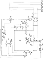
- the drawing shows an embodiment of the invention in a single figure.
- a temperature sensor 3 is located in the flow line 1 of the boiler 2, which gives the actual value of the controlled variable as a load signal to an input controller 4. Its returned output signal is proportional to the control deviation from 0-10 volts and corresponds to the respective boiler load within the control load range.
- the load signal is sent via a device 5 to a control unit 6 for the stepless change in the speed of a drive motor 7 of the induced draft fan 8 in the exhaust gas duct 9. In the device 5, the load signal experiences a lower and an upper limit in accordance with the system-related minimum and maximum speed.
- a fresh air flap 10 on the boiler 2 is opened.
- the fresh air flap 10 is regulated by closing and opening by a thermostat 11 in the flow line 1 via a servomotor 12.
- the induced draft fan 8 continues to run at a constant, lowest speed.
- Safety functions are performed by a limiter 13 in the flow line 1, which can close the fresh air flap 10 and switch off the suction fan 8.
- the fresh air flap 10 is closed via a spring return 14 of the servomotor 12, so that the device is also effective in the event of a power failure.
- the load signal also passes from the input controller 4 to a secondary air controller 15 which, as a follow-up controller, adjusts an actuator 16 proportional to the boiler load and mechanically actuates a secondary air control flap 17 via a cam 18.
- the motor 19 of the secondary air blower 20 runs at a constant speed.
- the load signal also passes from the input controller 4 to an electronic converter 21, where it is converted into pulses, the frequency of which corresponds to the respective boiler load.
- the pulses are added in a pulse counter 22. After a predetermined sum of pulses has been reached, a pulse is sent to a flip-flop 23, which acts alternately on the motor 24 of a scraper device 26 installed in the grate 25 and on the motor 27 of a detoxification device 28. The stoking or detoxification processes thus initiated then run automatically.
Landscapes
- Engineering & Computer Science (AREA)
- Chemical & Material Sciences (AREA)
- Combustion & Propulsion (AREA)
- Mechanical Engineering (AREA)
- General Engineering & Computer Science (AREA)
- Regulation And Control Of Combustion (AREA)
- Control Of Steam Boilers And Waste-Gas Boilers (AREA)
Description
- Die Erfindung betrifft eine Regelung eines Saugzugventilators und einer Frischluftklappe an Heizkesseln zur Verfeuerung fester Brennstoffe, über ein von der jeweiligen Kessellast abhängiges Lastsignal.
- Der Saugzugventilator hat die Aufgabe, für einen ausreichenden Zug zu sorgen. Die Frischluftklappe dient der Anpassung der Primärluftzufuhr an die jeweilige Kessellast. Eine geringe Kessellast, gemessen an der jeweils vorliegenden Vorlauftemperatur, erfordert eine Verringerung der Primärluftzufuhr. Eine höhere Kessellast erfordert hingegen eine Erhöhung der Primärluftzufuhr.
- Die Anpassung erfolgt gemäß der DE-B-1 454 462 durch stärkeres Öffnen oder Schließen der Frischluftklappe, wobei der Saugzugventilator mit voller Leistung in Betrieb ist. Eine ähnliche Anpassung offenbart die DE-C-1 055 740, gemäß der die Stellung der Frischluftklappe und der Rauchgasklappe über ein Lastsignal verändert werden soll.
- Die volle Leistung des Saugzugventilators wird nur bei voll geöffneter Frischluftklappe benötigt. Bei teilweise geschlossener Frischluftklappe wird die zum Betrieb des Saugzugventilators eingesetzte Energie hingegen teilweise vergeudet. Zudem ist das Regelverhalten bei einem in allen Phasen mit voller Drehzahl laufenden Saugzugventilator nicht besonders günstig.
- Der Saugzugventilator und die Frischluftklappe sollen so geregelt werden, daß bei optimalem Regelverhalten eine höchstmögliche Energieersparnis erzielt wird.
- Gemäß der Erfindung wird dieses erreicht durch die im Kennzeichen des Patentanspruches 1 genannten Maßnahmen.
- In einem festgelegten Regellastbereich, der bei etwa 15% bis 100% der Kesselleistung liegt, erfolgt die Steuerung durch stufenlose Veränderung der Saugzugdrehzahl, d. h. eine hohe Kessellast führt zu einer hohen Drehzahl und eine niedrige Kessellast zu einer niedrigen Drehzahl. Dabei ist die Frischluftklappe vollständig geöffnet. Im Lastbereich unter 15% wird hingegen die Frischluftklappe durch intermittierendes Auf-Zu-Fahren betätigt, wobei der Saugzugventilator mit seiner niedrigsten Drehzahl konstant weiter läuft. Das Lastsignal kann in bekannter Weise von der Vorlauftemperatur oder vom Dampfdruck abhängig sein.
- Im Gegensatz zu der bekannten Steuerung erfolgt die Regulierung der Primärluftzufuhr somit nicht bei voller Leistung des Saugzugventilators durch Veränderung der Offenstellung der Frischluftklappe, sondern direkt durch Veränderung der Leistung des Saugzugventilators. Erst wenn eine weitere Leistungserniedrigung durch weitere Verringerung der Drehzahl keine positiven Ergebnisse mehr bringen würde, erfolgt eine Regulierung durch die Frischluftklappe. Somit ergibt sich ein wesentlich günstigeres Regelverhalten in Verbindung mit einer Energieersparnis.
- Außer dem Saugzugventilator besitzen Heizkessel der vorgenannten Art eine Sekundärluftzufuhr. Die Menge der zugeführten Sekundärluft ist ebenfalls abhängig von der jeweiligen Kessellast. Es ist deshalb zweckmäßig, das Lastsignal zusätzlich über einen Sekundärluftregler auf den Stellantrieb einer Sekundärluftregelklappe einwirken zu lassen.
- Ferner ist der Schlackenanfall von der Kessellast abhängig. Über einen Spannungs-Impulswandler und einen nachgeschalteten Impulszähler kann deshalb das Lastsignal auf eine in Zeitabständen betätigte Schür- und Entschlackungseinrichtung einwirken. Das Schüren und Entschlacken erfolgt dadurch in Zeitabständen, die der jeweiligen Kessellast entsprechen.
- Es ist möglich, das Lastsignal wie beschrieben direkt auf die Sekundärluftzufuhr und Entschlakkung einwirken zu lassen. Eine indirekte Einwirkung über die jeweilige Drehzahl des Saugzugventilators ist ebenfalls denkbar.
- Die Zeichnung stellt in einer einzigen Figur ein Ausführungsbeispiel der Erfindung dar.
- In der Vorlaufleitung 1 des Kessels 2 sitzt ein Temperaturgeber 3, der den Istwert der Regelgröße als Lastsignal an einen Eingangsregler 4 gibt. Dessen rückgeführtes Ausgangssignal ist von 0-10 Volt proportional zur Regelabweichung und entspricht der jeweiligen Kessellast innerhalb des Regellastbereiches. Das Lastsignal gelangt über eine Einrichtung 5 an eine Regeleinheit 6 für die stufenlose Veränderung der Drehzahl eines Antriebsmotores 7 des Saugzugventilators 8 im Abgaskanal 9. In der Einrichtung 5 erfährt dabei das Lastsignal eine untere und obere Begrenzung entsprechend der anlagebedingten minimalen und maximalen Drehzahl.
- Innerhalb des Regellastbereiches, d. h. in einem Bereich von etwa 15-100% der Kesselleistung, ist eine Frischluftklappe 10 am Kessel 2 geöffnet. Bei sehr kleinen Kesselbelastungen, die durch die Saugzugregelung nicht mehr beherrscht werden, wird durch einen Thermostaten 11 in der Vorlaufleitung 1 über einen Stellmotor 12 die Frischluftklappe 10 durch Schließen und Öffnen geregelt. Der Saugzugventilator 8 läuft dabei mit konstanter, kleinster Drehzahl weiter.
- Sicherheitsfunktionen übernimmt ein Begrenzer 13 in der Vorlaufleitung 1, welcher die Frischluftklappe 10 schließen und den Saugzugventilator 8 abschalten kann. Das Schließen der Frischluftklappe 10 erfolgt über einen Federrücklauf 14 des Stellmotores 12, so daß die Einrichtung auch bei Stromausfall wirksam ist.
- Das Lastsignal gelangt vom Eingangsregler 4 zusätzlich an einen Sekundärluftregler 15, der als Nachlaufregler einen Stellantrieb 16 proportional zur Kessellast einstellt und eine Sekundärluftregelklappe 17 über eine Kurvenscheibe 18 mechanisch betätigt. Der Motor 19 des Sekundärluftgebläses 20 läuft mit konstanter Drehzahl.
- Das Lastsignal gelangt ferner vom Eingangsregler 4 zu einem elektronischen Wandler 21, wo eine Umwandlung in Impulse erfolgt, deren Frequenz der jeweiligen Kessellast entspricht. In einem Impulszähler 22 werden die Impulse addiert. Nach Erreichen einer festgelegten Summe an Impulsen erfolgt eine Impulsgabe an einen FlipFlop 23, der im Wechsel auf den Motor 24 einer im Rost 25 eingebauten Schüreinrichtung 26 und auf den Motor 27 einer Entschlackungseinrichtung 28 einwirkt. Die damit eingeleiteten Schür- bzw. Entschlackungsvorgänge laufen dann selbsttätig ab.
Claims (5)
Priority Applications (1)
| Application Number | Priority Date | Filing Date | Title |
|---|---|---|---|
| AT81104396T ATE9181T1 (de) | 1980-07-09 | 1981-06-06 | Regelung eines saugzugventilators und einer frischluftklappe an heizkesseln zur verfeuerung fester brennstoffe. |
Applications Claiming Priority (2)
| Application Number | Priority Date | Filing Date | Title |
|---|---|---|---|
| DE3025966 | 1980-07-09 | ||
| DE3025966A DE3025966C2 (de) | 1980-07-09 | 1980-07-09 | Selbsttätige Regelung eines Saugzugventilators und einer Frischluftklappe an Heizkesseln zur Verfeuerung fester Brennstoffe |
Publications (3)
| Publication Number | Publication Date |
|---|---|
| EP0043455A2 EP0043455A2 (de) | 1982-01-13 |
| EP0043455A3 EP0043455A3 (en) | 1982-02-24 |
| EP0043455B1 true EP0043455B1 (de) | 1984-08-29 |
Family
ID=6106775
Family Applications (1)
| Application Number | Title | Priority Date | Filing Date |
|---|---|---|---|
| EP81104396A Expired EP0043455B1 (de) | 1980-07-09 | 1981-06-06 | Regelung eines Saugzugventilators und einer Frischluftklappe an Heizkesseln zur Verfeuerung fester Brennstoffe |
Country Status (3)
| Country | Link |
|---|---|
| EP (1) | EP0043455B1 (de) |
| AT (1) | ATE9181T1 (de) |
| DE (2) | DE3025966C2 (de) |
Families Citing this family (3)
| Publication number | Priority date | Publication date | Assignee | Title |
|---|---|---|---|---|
| DE3202671A1 (de) * | 1982-01-28 | 1983-08-04 | Hölter, Heinz, Dipl.-Ing., 4390 Gladbeck | Elektronische regeleinrichtung zur optimierung der verbrennungsluftzufuhr bei fossilen waermeerzeugern |
| JPS60169051A (ja) * | 1984-02-14 | 1985-09-02 | Rinnai Corp | 温風暖房機 |
| DE3817598A1 (de) * | 1988-05-24 | 1989-11-30 | Stahl Und Apparatebau Josef Sc | Vorrichtung zum regeln der verbrennungsleistung eines feststoffheizkessels |
Family Cites Families (4)
| Publication number | Priority date | Publication date | Assignee | Title |
|---|---|---|---|---|
| DE1055740B (de) * | 1957-02-19 | 1959-04-23 | Siemens Ag | Regelanordnung fuer Kessel, vorzugsweise Heizungskessel, mit einer in den Rost eingebauten Schuereinrichtung |
| DE1454462B1 (de) * | 1963-06-12 | 1970-05-21 | Omnical Ges Fuer Kessel Und Ap | Selbsttaetige Steuerung eines Saugzug- oder eines Unterwindventilators an Heizkesseln |
| FR2287655A1 (fr) * | 1974-10-08 | 1976-05-07 | Saunier Duval | Dispositif de regulation de chaudiere a gaz a tirage force |
| US3985294A (en) * | 1975-08-04 | 1976-10-12 | Foster Wheeler Energy Corporation | Furnace pressure control |
-
1980
- 1980-07-09 DE DE3025966A patent/DE3025966C2/de not_active Expired
-
1981
- 1981-06-06 EP EP81104396A patent/EP0043455B1/de not_active Expired
- 1981-06-06 DE DE8181104396T patent/DE3165760D1/de not_active Expired
- 1981-06-06 AT AT81104396T patent/ATE9181T1/de not_active IP Right Cessation
Also Published As
| Publication number | Publication date |
|---|---|
| EP0043455A3 (en) | 1982-02-24 |
| DE3165760D1 (en) | 1984-10-04 |
| DE3025966A1 (de) | 1982-01-21 |
| EP0043455A2 (de) | 1982-01-13 |
| ATE9181T1 (de) | 1984-09-15 |
| DE3025966C2 (de) | 1983-11-24 |
Similar Documents
| Publication | Publication Date | Title |
|---|---|---|
| DE19618573C1 (de) | Verfahren und Einrichtung zum Betrieb eines Gasbrenners | |
| DE102004048986B4 (de) | Verfahren zur Regelung eines Gasbrenners | |
| EP0275439B1 (de) | Einrichtung zur Leistungsregelung von brennstoffbefeuerten Wärmeerzeugern | |
| DE3100267A1 (de) | Verfahren und vorrichtung zur optimierung des betriebs einer viele brenner aufweisenden natuerlichen zugverbrennungszone | |
| EP0484280A2 (de) | Anlage zur Reinigung von schadstoffbelasteter Luft | |
| EP0043455B1 (de) | Regelung eines Saugzugventilators und einer Frischluftklappe an Heizkesseln zur Verfeuerung fester Brennstoffe | |
| EP0499976B1 (de) | Verfahren zum Betreiben einer Müllverbrennungsanlage | |
| DE4312801A1 (de) | Verfahren zur Steuerung eines Gas-Gebläsebrenners | |
| DE2405180A1 (de) | Einrichtung in einer brennkraftmaschine zur verhinderung eines dieselns | |
| DE4408801C2 (de) | Gasgebläsebrenner | |
| DE19537773C2 (de) | Verfahren und Vorrichtung zum Zünden eines Gasgebläsebrenners | |
| DE19714073C2 (de) | Wirbelschichtanlage, insbesondere für Schlamm | |
| EP0615095A1 (de) | Feuerungsautomat | |
| DE19501749C2 (de) | Verfahren und Vorrichtung zum Steuern eines Gas-Gebläsebrenners | |
| DE3248623C1 (de) | Verfahren und Vorrichtung zum Vorwaermen der Verbrennungsmedien,insbesondere fuer die Beheizung von Winderhitzern fuer Hochoefen | |
| EP4083507B1 (de) | Verfahren zum prüfen einer rückschlagklappe in einer heizungsanlage | |
| AT397851B (de) | Heizgerät | |
| AT402443B (de) | Verfahren zum betrieb eines wasserheizers und einrichtung zur durchführung des verfahrens | |
| DE2834025A1 (de) | Gasbeheiztes geraet, insbesondere wassererhitzer | |
| EP4585858B1 (de) | Verbrennungsvorrichtung mit adaptivem elektronischen verbund | |
| DE2656580A1 (de) | Steuereinrichtung fuer eine abgassperre | |
| DE3221660A1 (de) | Verfahren zum zwecke der optimalen verbrennung bei feuerungen | |
| DE2950690A1 (de) | Vorrichtung zur regelung der verbrennungsluftmenge einer feuerstaette | |
| EP0327785B1 (de) | Verfahren zum Steuern einer Wärmequelle | |
| DE1902063A1 (en) | Controlling oil or gas fired furnaces over - wide feed-ranges |
Legal Events
| Date | Code | Title | Description |
|---|---|---|---|
| PUAI | Public reference made under article 153(3) epc to a published international application that has entered the european phase |
Free format text: ORIGINAL CODE: 0009012 |
|
| PUAL | Search report despatched |
Free format text: ORIGINAL CODE: 0009013 |
|
| AK | Designated contracting states |
Designated state(s): AT BE CH DE FR NL |
|
| 17P | Request for examination filed |
Effective date: 19811020 |
|
| AK | Designated contracting states |
Designated state(s): AT BE CH DE FR NL |
|
| GRAA | (expected) grant |
Free format text: ORIGINAL CODE: 0009210 |
|
| AK | Designated contracting states |
Designated state(s): AT BE CH DE FR LI NL |
|
| REF | Corresponds to: |
Ref document number: 9181 Country of ref document: AT Date of ref document: 19840915 Kind code of ref document: T |
|
| REF | Corresponds to: |
Ref document number: 3165760 Country of ref document: DE Date of ref document: 19841004 |
|
| ET | Fr: translation filed | ||
| BECH | Be: change of holder |
Free format text: 840829 *OMNICAL G.M.B.H. |
|
| PLBE | No opposition filed within time limit |
Free format text: ORIGINAL CODE: 0009261 |
|
| STAA | Information on the status of an ep patent application or granted ep patent |
Free format text: STATUS: NO OPPOSITION FILED WITHIN TIME LIMIT |
|
| 26N | No opposition filed | ||
| REG | Reference to a national code |
Ref country code: CH Ref legal event code: PUE Owner name: OMNICAL GMBH |
|
| REG | Reference to a national code |
Ref country code: FR Ref legal event code: TP |
|
| NLS | Nl: assignments of ep-patents |
Owner name: OMNICAL GMBH TE DIETHOELZTAL-EWERSBACH, BONDSREPUB |
|
| PGFP | Annual fee paid to national office [announced via postgrant information from national office to epo] |
Ref country code: CH Payment date: 19900423 Year of fee payment: 10 |
|
| PGFP | Annual fee paid to national office [announced via postgrant information from national office to epo] |
Ref country code: BE Payment date: 19900430 Year of fee payment: 10 |
|
| PGFP | Annual fee paid to national office [announced via postgrant information from national office to epo] |
Ref country code: FR Payment date: 19900507 Year of fee payment: 10 |
|
| PGFP | Annual fee paid to national office [announced via postgrant information from national office to epo] |
Ref country code: AT Payment date: 19900516 Year of fee payment: 10 |
|
| PGFP | Annual fee paid to national office [announced via postgrant information from national office to epo] |
Ref country code: NL Payment date: 19900630 Year of fee payment: 10 |
|
| PGFP | Annual fee paid to national office [announced via postgrant information from national office to epo] |
Ref country code: DE Payment date: 19910423 Year of fee payment: 11 |
|
| PG25 | Lapsed in a contracting state [announced via postgrant information from national office to epo] |
Ref country code: AT Effective date: 19910606 |
|
| PG25 | Lapsed in a contracting state [announced via postgrant information from national office to epo] |
Ref country code: LI Effective date: 19910630 Ref country code: CH Effective date: 19910630 Ref country code: BE Effective date: 19910630 |
|
| BERE | Be: lapsed |
Owner name: OMNICAL G.M.B.H. Effective date: 19910630 |
|
| PG25 | Lapsed in a contracting state [announced via postgrant information from national office to epo] |
Ref country code: NL Effective date: 19920101 |
|
| NLV4 | Nl: lapsed or anulled due to non-payment of the annual fee | ||
| PG25 | Lapsed in a contracting state [announced via postgrant information from national office to epo] |
Ref country code: FR Effective date: 19920228 |
|
| REG | Reference to a national code |
Ref country code: CH Ref legal event code: PL |
|
| REG | Reference to a national code |
Ref country code: FR Ref legal event code: ST |
|
| PG25 | Lapsed in a contracting state [announced via postgrant information from national office to epo] |
Ref country code: DE Effective date: 19930302 |