EP0043532A2 - Circuit digital à semiconducteur pour orgue électronique - Google Patents
Circuit digital à semiconducteur pour orgue électronique Download PDFInfo
- Publication number
- EP0043532A2 EP0043532A2 EP81105031A EP81105031A EP0043532A2 EP 0043532 A2 EP0043532 A2 EP 0043532A2 EP 81105031 A EP81105031 A EP 81105031A EP 81105031 A EP81105031 A EP 81105031A EP 0043532 A2 EP0043532 A2 EP 0043532A2
- Authority
- EP
- European Patent Office
- Prior art keywords
- amplitude
- assigned
- sound signal
- control
- output
- Prior art date
- Legal status (The legal status is an assumption and is not a legal conclusion. Google has not performed a legal analysis and makes no representation as to the accuracy of the status listed.)
- Granted
Links
Images

Classifications
-
- G—PHYSICS
- G10—MUSICAL INSTRUMENTS; ACOUSTICS
- G10H—ELECTROPHONIC MUSICAL INSTRUMENTS; INSTRUMENTS IN WHICH THE TONES ARE GENERATED BY ELECTROMECHANICAL MEANS OR ELECTRONIC GENERATORS, OR IN WHICH THE TONES ARE SYNTHESISED FROM A DATA STORE
- G10H1/00—Details of electrophonic musical instruments
- G10H1/18—Selecting circuits
- G10H1/183—Channel-assigning means for polyphonic instruments
Definitions
- German ⁇ P 29 48 769.2 (VPA 79 P 1189) there is a digital semiconductor circuit for an electronic organ with a number of control inputs applied via the manual corresponding to the number of play keys in the manual of the organ and with one of an oscillator system with periodic electrical vibrations described number of sound signal inputs, in which a control input is assigned to a game key of the manual and a sound signal input to a sound frequency, in which a 'sound signal output is also provided for the application of an electro-acoustic transducer and finally for the application the control signals serving the control inputs correspond to the logic levels.
- the individual control inputs are each assigned to a cell of a clock-controlled shift register operated as a parallel series converter, that the signal output of the shift register and the clock pulses provided for its operation are also used to control a switching system which, on the other hand, are connected to the
- the totality of the provided sound signal inputs is such that the number of sound signal outputs is also lower than the number of control inputs and each of the sound signal outputs is assigned an amplitude shaper and that finally the outputs of the amplitude shifters are connected to an electro-acoustic transducer.
- the switching system is designated VM in the DE application.
- An amplitude former AF i is connected to each of the audio outputs AU i provided for it.
- the index "i" assumes a value corresponding to one of the integers from 1 to n for n sound outputs and amplitude shapers. They are given, for example, in Figure 1 of the parent application.
- the invention relates to a digital semiconductor circuit for an electronic organ with a number of control inputs and the number of control keys corresponding to the number of the manual of the organ with a number of sound signal inputs to which an oscillator system is subjected to periodic electrical vibrations, in which one control input each has a game key in the manual and one sound signal input is assigned to one sound frequency, and in which a sound signal output is also provided for the application of an electro-acoustic transducer and in which the control signals used to apply the control inputs correspond to the logic levels "1" and "0", in which also the individual control inputs are each assigned to a cell of a clock-controlled shift register operated as a parallel series converter, in which the signal output of the shift register as well the clock pulses provided for its operation are used to control a switching system which, on the other hand, is provided with the entirety of the sound signal inputs provided, in which the number of sound signal outputs is also lower than the number of control inputs and each of the sound signal outputs is assigned an amplitude shaper
- each of the octaves provided in the manual is assigned a mixing stage matched to the octave in question and that the output of each of the provided amplitude shapers is assigned to the octave in question in accordance with the octave associated with the tone signal present in the respective amplitude shaper Mixing stage can be switched on.
- One way to do this is to assign a sensor to the individual amplitude shapers that is capable of measuring the octave of the one in question fenden amplitude shaper to detect any pending signal based on the oscillation frequency and then ensures via logic that the sound signal output is automatically connected to the mixer that is assigned to the recognized octave.
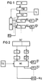
- FIGS. 1, 2 and 3 are block diagrams of a semiconductor circuit in accordance with the DE application in FIG. 2, a section of this block diagram provided with details that are essential for the present embodiment, and in FIG. 3, an embodiment according to the present invention to be carried out on the basis of the circuit parts apparent from this section Invention shown.
- a pressed play key in the manual M of the organ generates a "1" at the control input E of the semiconductor circuit that is individually assigned to it, while the control input E assigned to a play key that is not actuated has the level "0".
- the clock generator TG supplies a shift register PSW (the input shift register) with the clock pulses required for shifting out the information formed in the shift register PSW between the individual polling cycles.
- the information in the shift register PSW is fed from the game keys of the manual via the respectively assigned control input E_ to one of the memory cells provided in the shift register PSW.
- the order of the game buttons in the manual M corresponds to the order of the memory cells assigned to the individual game buttons in the shift register PSW.
- the information periodically shifted out of the shift register PSW reaches the actual switching circuit, the input of which is through the so-called channel selection KW is formed.
- the channel selector KW which is described in detail in the DE application, emits a number of mutually identical branches, each of which leads to one of the provided amplitude shapers AF i , where i indicates the number of the amplitude shaper. Its output is labeled AG i .
- the individual amplitude former AF i is preceded by an output part V i of the switching circuit, which is supplied with the necessary digital information on the one hand via the channel selector KW, on the other hand by the sound signal generator TOS and finally by a sound address counter TAZ.
- This tone address counter TAZ takes over the shifting acts serving for pushing out the information from the input shift register PSW as counting pulses in the individual polling cycles.
- the tone address counter TAZ consists of two parts, of which the first part consists of four series-connected binary counting stages, which are switched in such a way that the first part of the counter only counts to "12" in order to return to the initial state "zero" when the thirteenth counting pulse arrives "to be switched.
- the second part of the tone address counter TAZ consists of three series-connected counter stages, which are connected so that the highest count corresponds to the number k of the intended octaves.
- the second part of the counter TAZ receives its counting pulses each time the first part of the counter TAZ changes from the count "12" to the count "zero".
- each time a "1" is output from the shift register PSW the respectively associated count of both parts of the sound address counter TAZ is coded out and temporarily stored in one of the intended output parts V i .
- two series memories S are in each of the provided output parts V i , that is, output channels, of the switching circuit as S provided, when the exit of a "1" from the shift register PSW save the currently existing count of the two parts of the sound address counter TAZ, provided that the output channel V i concerned is controlled by the channel selector KW for control by the Shift register PSW given "1" is released.
- the name of the sound of the game key belonging to the "1" which is just leaving the shift register is stored in the storage part S and the number of the associated octave - in the form of the current count of the two parts of the sound address counter TAZ - is stored in the storage part S.
- FIG. 2 shows further details regarding the individual output channel V i .
- the two series memories S and S of the individual output channel V i of the switching circuit are used via a decoder D and D, respectively, to act upon further circuit parts, the design of which can be seen from the main application. However, because they are insignificant in connection with the invention, they are summarized here in a block labeled WS.
- the circuit parts contained in the block WS represent a switching, controlled via the decoders D and D *, between the sound signal inputs supplied by the oscillation system which supplies the required sound signals in the form of corresponding square waves by the sound vibrations of at least one octave and the individual output channels V i and thus the individual amplitude shapers AF i represents.
- the memory S provided for storing the number k of the game key controlling the respective amplitude shaper AF i in manual M should now also carry the index "i" in view of its fixed assignment to the amplitude shaper AF i .
- each of these ten amplitude formers AF i is a series memory S 1 storing the octave k and vice versa each of the ten provided Series S i memory according to one of ten amplitude former AF i individually assigned.
- the individual for recording the address of the currently for the actuation of the relevant AF i Amplitudenformers binding octave provided series memory S i are placed with their outputs information to a respective Adressierdekoder AS i.
- the same addressing decoders AS 1 to AS 10 each have k outputs, where k is the number of octaves provided.
- each of the address decoders has ten outputs which, via appropriately designed logic circuits inside the address decoder AS i, have such inputs to the inputs acted upon by one of the (three) memory cells of the memory S 1 * of the AdreB decoder are switched so that when the decoder is loaded with one of the k intended states of the associated memory S i *, the output assigned to the current state of the memory S i receives an output signal from the ten outputs of the relevant AdreB decoder, while all other outputs receive no signal receive.
- the intended amplitude formers AF i that is to say in the example the amplitude formers AF 1 to AF 10 , are connected with their output AG i (ie AG 1 to AG 10 ), each via a resistor R to the one current-carrying connection of k transistors T ij . Since a total of n amplitude formers AF i are provided, there are consequently n. k such transistor figures in the circuit. This n. k transistors are preferably given by mutually identical MOS field-effect transistors of the enhancement type, the source connections of which are applied to the respectively assigned output AG i of the n amplitude shapers AF i provided in the manner shown in FIG. 3.
- the first index "i" in the designation T ij for the individual transistor also indicates the number "i" of that address decoder AD i and thus of the memory Si by which the control electrode, that is to say the gate of the transistor T ij in question, is controlled.
- k mixing stages Mi j are provided, where j is the number of the individual octave to which the respective mixing stage is permanently assigned.
- Each of these k mixer stages can be connected to each of the n amplitude formers AF i provided via one of the transistors T ij provided, with the second current-carrying connection, ie the drain, of which the input of the respective mixer stage Mi j is connected.
- the number of these transistors T ij is evidently equal to n. k, that is, with ten amplitude formers AF i and ten mixer stages Mi j , one hundred.
- the transistor T ij provides the connection between the output AG i des i-th amplitude shaper AF i and the j-th mixer Mi j . This requires that the gate of the transistor T ij through that of the octave with the Number j assigned control output of the decoder with number i is controlled.
- the output A j of the individual mixer stage Mi j is expediently not connected directly to the electro-acoustic transducer to be controlled, that is to say a loudspeaker, but via a sinusoidal filter matched to the amplitude in question.
- a plurality of loudspeakers optionally controlled in different ways by the provided mixing stages Mi j, can be provided.
Landscapes
- Physics & Mathematics (AREA)
- Engineering & Computer Science (AREA)
- Acoustics & Sound (AREA)
- Multimedia (AREA)
- Electrophonic Musical Instruments (AREA)
Applications Claiming Priority (2)
| Application Number | Priority Date | Filing Date | Title |
|---|---|---|---|
| DE3025643 | 1980-07-07 | ||
| DE19803025643 DE3025643A1 (de) | 1980-07-07 | 1980-07-07 | Digitale halbleiterschaltung fuer eine elektronische orgel |
Publications (3)
| Publication Number | Publication Date |
|---|---|
| EP0043532A2 true EP0043532A2 (fr) | 1982-01-13 |
| EP0043532A3 EP0043532A3 (en) | 1985-05-02 |
| EP0043532B1 EP0043532B1 (fr) | 1987-12-23 |
Family
ID=6106562
Family Applications (1)
| Application Number | Title | Priority Date | Filing Date |
|---|---|---|---|
| EP19810105031 Expired EP0043532B1 (fr) | 1980-07-07 | 1981-06-29 | Circuit digital à semiconducteur pour orgue électronique |
Country Status (3)
| Country | Link |
|---|---|
| EP (1) | EP0043532B1 (fr) |
| JP (1) | JPS5748794A (fr) |
| DE (1) | DE3025643A1 (fr) |
Cited By (1)
| Publication number | Priority date | Publication date | Assignee | Title |
|---|---|---|---|---|
| EP1900616A2 (fr) | 2006-09-15 | 2008-03-19 | ThyssenKrupp Automotive Systems GmbH | Suspension de la cabine conducteur |
Family Cites Families (4)
| Publication number | Priority date | Publication date | Assignee | Title |
|---|---|---|---|---|
| US3696201A (en) * | 1970-11-12 | 1972-10-03 | Wurlitzer Co | Digital organ system |
| US4108038A (en) * | 1975-04-04 | 1978-08-22 | Nippon Gakki Seizo Kabushiki Kaisha | Time shared tone keying system in electronic musical instrument |
| JPS5245322A (en) * | 1975-08-06 | 1977-04-09 | Kawai Musical Instr Mfg Co Ltd | Circuit for selecting key signals in electronic musical instrument |
| DE2948769A1 (de) * | 1979-12-04 | 1981-06-11 | Siemens AG, 1000 Berlin und 8000 München | Digitale halbleiterschaltung fuer eine elektronische orgel |
-
1980
- 1980-07-07 DE DE19803025643 patent/DE3025643A1/de active Pending
-
1981
- 1981-06-29 EP EP19810105031 patent/EP0043532B1/fr not_active Expired
- 1981-07-07 JP JP56106187A patent/JPS5748794A/ja active Pending
Cited By (1)
| Publication number | Priority date | Publication date | Assignee | Title |
|---|---|---|---|---|
| EP1900616A2 (fr) | 2006-09-15 | 2008-03-19 | ThyssenKrupp Automotive Systems GmbH | Suspension de la cabine conducteur |
Also Published As
| Publication number | Publication date |
|---|---|
| EP0043532B1 (fr) | 1987-12-23 |
| DE3025643A1 (de) | 1982-02-04 |
| EP0043532A3 (en) | 1985-05-02 |
| JPS5748794A (en) | 1982-03-20 |
Similar Documents
| Publication | Publication Date | Title |
|---|---|---|
| DE2237594B2 (de) | System zur Erzeugung von Tonwellenformen durch Abtasten gespeicherter Wellenformen für ein elektronisches Musikinstrument | |
| DE2712226A1 (de) | Tongeneratoranordnung, insbesondere fuer ein elektronisches musikinstrument | |
| DE2149104A1 (de) | Verfahren und einrichtung zum adressieren einer speicherstelle mit wahlweise bestimmbaren geschwindigkeiten | |
| DE2152861A1 (de) | Elektronisches Tasten-Musikinstrument | |
| DE2920298A1 (de) | Binaere interpolatorschaltung fuer ein elektronisches musikinstrument | |
| DE3015455A1 (de) | Elektronisches musikinstrument | |
| DE3332477C2 (de) | Elektronisches Musikinstrument mit einer Vorrichtung zur Lokalisierung von Klangbildern | |
| DE3630611A1 (de) | Elektronisches musikinstrument | |
| DE3237403C2 (fr) | ||
| EP0042555B1 (fr) | Méthode de contrôle digital de l'enveloppe dans un instrument de synthèse musicale polyphonique, et circuits pour mettre en oeuvre cette méthode | |
| DE2539166A1 (de) | Elektronisches musikinstrument | |
| DE2357167A1 (de) | Elektronisches musikinstrument | |
| DE2828919A1 (de) | Polyphone syntheseschaltung fuer periodische signale und damit ausgestattetes elektronisches musikinstrument | |
| DE2951514A1 (de) | Tasteneingabevorrichtung, insbesondere fuer einen elektronischen rechner | |
| EP0217122A1 (fr) | Circuit comportant une mémoire en forme de matrice pour ajuster de façon variable le retard des signaux digitaux | |
| DE2306527C3 (de) | Abtastmodulationsschaltung für ein elektronisches Musikinstrument | |
| DE2309321A1 (de) | Elektronisches musikinstrument | |
| DE2836736B2 (de) | Verfahren zur Aufzeichnung von beim Spielen eines tastenbetätigten Musikinstruments entstehenden Tonsignalen und den damit verbundenen Spielausdrücken, insbesondere der Lautstärke, entsprechenden Datensignalfolgen auf einem Aufzeichnungsträger und Vorrichtung zur Durchführung des Verfahrens | |
| DE2228053C2 (de) | Einrichtung zur automatischen Baßbegleitung in einem elektronischen Musikinstrument | |
| EP0043532B1 (fr) | Circuit digital à semiconducteur pour orgue électronique | |
| DE2639606A1 (de) | Automatisches arpeggiogeraet fuer elektronische musikinstrumente | |
| EP0213584A2 (fr) | Arrangement d'un circuit avec un montage de mémoire en forme de matrice pour un retard de signaux digitaux à réglage variable | |
| DE2836737A1 (de) | Verfahren und vorrichtung zur registrierung digitaler signale zur betaetigung von solenoiden, insbesondere elektronischer klaviere | |
| EP0043093B1 (fr) | Circuit digital à semiconducteur pour orgue électronique | |
| DE69227083T2 (de) | Vorrichtung zur Hinzufügung von Toneffekten |
Legal Events
| Date | Code | Title | Description |
|---|---|---|---|
| PUAI | Public reference made under article 153(3) epc to a published international application that has entered the european phase |
Free format text: ORIGINAL CODE: 0009012 |
|
| 17P | Request for examination filed |
Effective date: 19811028 |
|
| AK | Designated contracting states |
Designated state(s): FR GB |
|
| PUAL | Search report despatched |
Free format text: ORIGINAL CODE: 0009013 |
|
| AK | Designated contracting states |
Designated state(s): FR GB |
|
| 17Q | First examination report despatched |
Effective date: 19870303 |
|
| GRAA | (expected) grant |
Free format text: ORIGINAL CODE: 0009210 |
|
| AK | Designated contracting states |
Kind code of ref document: B1 Designated state(s): FR GB |
|
| ET | Fr: translation filed | ||
| GBT | Gb: translation of ep patent filed (gb section 77(6)(a)/1977) | ||
| PLBE | No opposition filed within time limit |
Free format text: ORIGINAL CODE: 0009261 |
|
| STAA | Information on the status of an ep patent application or granted ep patent |
Free format text: STATUS: NO OPPOSITION FILED WITHIN TIME LIMIT |
|
| 26N | No opposition filed | ||
| PG25 | Lapsed in a contracting state [announced via postgrant information from national office to epo] |
Ref country code: GB Effective date: 19890629 |
|
| GBPC | Gb: european patent ceased through non-payment of renewal fee | ||
| PG25 | Lapsed in a contracting state [announced via postgrant information from national office to epo] |
Ref country code: FR Free format text: LAPSE BECAUSE OF NON-PAYMENT OF DUE FEES Effective date: 19900228 |
|
| REG | Reference to a national code |
Ref country code: FR Ref legal event code: ST |